


markdd
-
Posts
3,424 -
Joined
-
Last visited
Content Type
Profiles
Forums
Events
Articles
Marionette
Store
Everything posted by markdd
-
search functionality in Resource Manager
markdd replied to grant_PD's question in Wishlist - Feature and Content Requests
Click the little pull down arrow on the left of the search field. All will be revealed! -
Receive shadows is correct. Turn it on and it should stop beams going through solid objects. You will need to re render to see the effect although it looks to me from the photo that there is no light coming from the fixture which points to a further problem. Are you using a symbol that has shipped with VW Spotlight? Post the file if you like and I could take a look.
-
Make sure that you have "receive shadows" turned on in your Renderworks background
-
Some very rudimentary movement of items has been achieved using Marrionette nodes and @Alan Woodwell is probably the guy to ask about that. There is a video he made below. Vectorworks is primarily designed as a 2D/3D drafting and render programme and at this it excels. If you want to create scenic animations then you can export VW models to other software like Cinema4D which can handle this type of work. Good luck. It would be interesting to know what you discover. Of course if you just want static presentation slides or the ability to model positions of scenery, then VW will handle this with ease and setting up different scenes and positions of objects is easy using classes and saved views with any moving scenery pieces as separate symbols.
-
cycling through overlapping objects
markdd replied to wingchudesign's question in Wishlist - Feature and Content Requests
Does the "Select Coincidence" function not answer this need or do you mean something else? -
Viewports, sheet layers and export probs with scale.VW 17, Mac
markdd replied to Avellana's question in Troubleshooting
The greyed out rectangle is the size of the paper you are printing to. Go to File, Page Setup and uncheck page breaks. This is also where you can change the size of the paper you are printing on to. Once you have the correct paper size I find it is more useful to keep the paper size visible. With regard to your viewports, then it looks like you need to look at the design layer scale of the source objects or the scale of the viewports on the sheet layer. You should be able to adjust the scale of the viewport from the object info palette. Now you know what the grey rectangle represents, it might help you with making decisions about what scale you should be printing at. -
Rotate Tool - Alignment Mode I understand the principle behind this mode but at the moment can't really think of a real world use for it. The help section is vague and the video tip is very brief. Could the forum help me with a bit more of an explanation of this mode and more usefully give me a really good real world application. Many thanks
-
Does the "fix profile" option not do what you need?
-
I contributed to a post earlier in the year which I think is more or less what you are looking for.
-
This is very good advice!
-
I don't have a solution I'm afraid unless you want to post the file here and then I and others could take a look. You should definitely contact tech support though.
-
I'm afraid I don't have an easy solution. Did you backup your file? Most people set their files to backup every 15-20mins or after 20 or so commands so not much is lost if things go wrong.
-
Did you just have ETC Source 4 symbols in your drawing?
-
Document Settings/Document Preferences/Use Layer colours.
-
Do you have Layer colours enabled by mistake?
-
I am loathe to suggest a reinstall of the software but I have had problems with parametric tools in there past causing weird bugs like this. The advice was always a reinstall. You should contact tech support first before you do anything as time consuming as this just yet. Sorry not to be more helpful. Some of my wiser colleagues on this board will no doubt speak up a little later. This thread lists the problem following using a parametric object so you are not alone.
-
Can you post a couple of screen shots to help explain further?
-
This has happened to me once or twice before and has always been resolved with a restart of the program. Have you tried that yet?
-
Essentially the individual led sources in a fixture create a single beam. To help give the appearance of light emanating from across the whole LED array, I have started applying a glow texture to a "lens" in my symbols. This is classed separately and can be turned on or off as necessary. I'll try and post an example when I have a bit more time. Contained in the light info record there is a field named "Lens". Currently this unused in all the symbols that I know of but clearly VW has some plan or other for that at some stage. Perhaps @Rob Bookscould enlighten us!
-
Browse to Source Image button in Edit Texture window
markdd replied to bcd's question in Wishlist - Feature and Content Requests
Gotcha! Great idea! -
Yeah sorry. A bit garbled! You've got me thinking though! You could create 4 segments exactly along the path you want to follow including the heights and then use the Loft Surface tool.See pic

-
Browse to Source Image button in Edit Texture window
markdd replied to bcd's question in Wishlist - Feature and Content Requests
I think what you are asking for already exists. In the object info palette of an object with a texture applied there is a small pull-down arrow next to the texture dropdown. Is this what you mean?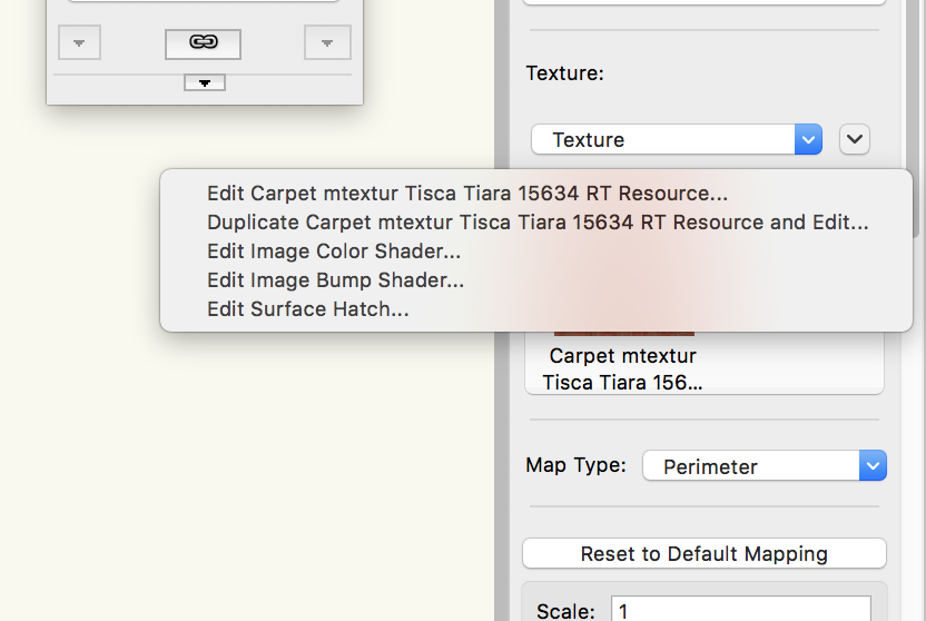
-
Used the deform tool too but results didn't look convincing enough aesthetically so used your extruded curve, sliced the angle I liked from the rear with the slice tool, extracted the curved surface, extruded it to your correct thickness, and then deformed it around your curve again!! Here is the result! I guess its all about what looks right! stairstring.vwx

-
I tried this and Kevin's method works well. In this instance though, would this not be a good application for using a texture?

-
can you post the drawing or paste the object into a blank file?

