.jpg.9135c1eaed5451dd8141a10c04bd5c89.jpg)
.jpg.4660f4199b0aad5241589b20923a1a19.jpg)
tekbench
-
Posts
89 -
Joined
-
Last visited
Recent Profile Visitors
1,839 profile views


-
Hello! I just saw this happen on my machine as well. I have been working along using the spacebar 'boomerang' tool for years. This morning, I went to grab my drawing and spacebar to pan while in the flyover tool. Did not work. I have never seen this tool fail. I have also always use the flyover tool in active layer plane origin mode. Today I started using rotate around selected objects, and that 'seems' to have broke the spacebar/pan function. At least that was the last change/thing I did before the spacebar to pan stopped working. I opened a Chrome tab, logged in here, did a search or two, found this thread. Went back to Vectorworks and stepped through re-pro'ing the issue. Issue disappeared. Can't repro, working fine. I've not done much of anything to this machine other than keep VW current with service packs. VW 2023 SP8 MacBook Pro M1 Max, 14" 2021 Monterey 12.5 23 gig Ram
-
.thumb.jpg.bf866c27e32041c9bc1071949e15dc32.jpg)
Circuit ID size mysteriously getting 'much bigger'.
tekbench replied to tekbench's topic in ConnectCAD
@Nikolay Zhelyazkov I tried replying to this thread yesterday from my phone, but it would never actually show up. i'd log in, type my reply, hit submit, and it would just clear out the page and the reply would never show up. There is apparently a bug filed on this now. Support (Rob N.) has a copy of the VW drawing file. I'm making do by cutting a pasting everything into a new drawing, and rebuilding my equipment, racks and room layout. Thankfully it's fairly fast to do all this, but I would like to get to the bottom of why it happened in the first place. Rob N. in support filed it back on 2/14/2023, but I don't have a bug number or anything for you. -
Rack Depth vs Usable Rack Depth (Rail to Rail Depth)
tekbench replied to alexmootv's topic in ConnectCAD
+1 as a 'thanks for the development' post. Nice to hear this is in the works. 👏 -
Circuit ID size mysteriously getting 'much bigger'.
tekbench replied to tekbench's topic in ConnectCAD
MacOS Monterey 12.5 Macbook Pro, 14", 2021 M1 Max Chip 32 gig Ram VW 2023, SP3 -
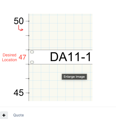
Are you asking for the RU number to be 'between' the two marks as opposed to 'where the rack space starts'? You want the number '47' to be directly adjacent to your gear "DA11-1" as opposed to seeing '47' Below your gear "DA11-1" in this case, no? AFAIK, all rack numbering is fixed to where the RU starts, moving from bottom to top. You can snap a rack ruler in there, and adjust it up or down so they line up with the actual physical RU space, but other than that I think they're fixed. racks and RU also, If I remember correctly, are fixed starting at zero, working bottom up. I had a whole crew that counted rack spaces top down, and it was kind of a mess at the end of the day.
-
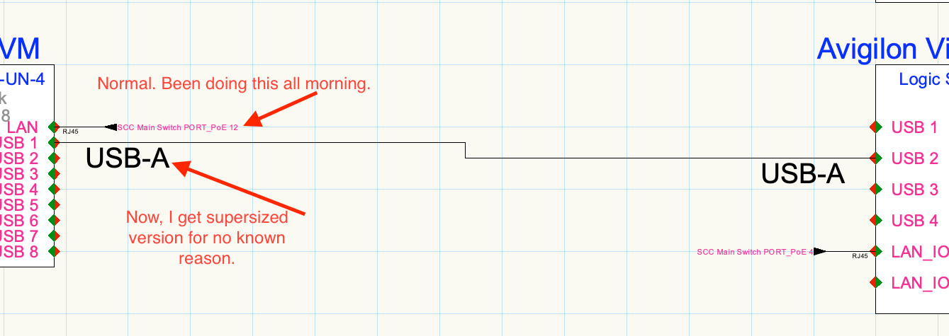
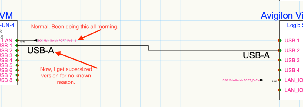
Have a project. Have a bunch of devices. I jump into a 'number' of devices, Edit, and make some changes to the device box (moved connectors down, made the box wider). Save. Connect some stuff. Eat lunch. Come back and one of the circuit ID's is stuck at Large scale. I delete and try again. Same issue. Try connections between two other devices. Same thing. Same issue with both the 'arrow' option and the 'polyline' option. Everything is stuck in this super large mode. File is sensitive, so I"m happy to email to support, but client doesn't want me posting it here for everyone to see. I WILL attach a screen snip showing the issue.
-
.LAZ file coming in to document way out of scale.
tekbench replied to tekbench's topic in Site Design
@Eric Gilbey, PLA Adding Eric: - Per our conversation today at the Vectorworks Open House, here's the thread. Huge Thank You for taking the time to push this up the developer flagpole (at least a little bit further than we have been able to). If the steps in this thread aren't clear enough, email me any time and I'm happy to walk anybody through what is happening. Kelly. -
This Just came up in a user meeting. I was trying to design a basic pump house layout and was using my swiss army knife, ConnectCAD. This is a total life saver. 1. Thank you. This is amazing. 2. how can I repay you? I have to admit, I have nothing quite this cool or useful to offer up. Kelly.
-
Edit Solid using 'Move 3D' not working as expected
tekbench replied to tekbench's question in Troubleshooting
Wow. I would have never ever caught that. I appreciate it! I'm sure I grabbed a corner and pulled it in or out at some point. and i'm assuming that 'scales' the solid as opposed to the way you would grab the corner of a rectangle and just pull it in to change the dimension. Thanks a ton. Just didn't even see that. Kelly. -
Edit Solid using 'Move 3D' not working as expected
tekbench replied to tekbench's question in Troubleshooting
Here you go. thanks for taking a look! TurnTableConsole.vwx -
Here goes: Creating a solid with two slots in it. A sheet of 3/4" plywood with two slots. easy. Create the solid, subtract a couple rectangles. No problem. the two rectangles are, say, 1 3/4" apart. Double click solid, enter 'edit solid' dialog. Move the two cutouts directly adjacent to each other. Exit. Verify that the cutout is now just one big hole. perfect. Now i'd like a 2" 'bar' between the two holes. Return to modify solid dialog. Select one of the cut outs, use 'Move 3D' to move one of the cut outs exactly 2" away from the other. Use the dimension tool. Check that the two items are, in fact, 2" from each other. Exit 'edit solid' dialog. Return to top/Plan, use dimension tool to check distance between items. Dimension tool shows 1 3/4" between items. What am I missing here? I have a screen cap showing the issue if that helps. I originally thought this was because in the 'regular' 2d move dialog, there was a 1/4" dimension in there from a previous action. But I changed that to x=0 and y=0 and have the same issue. It is like Move 3D moves the subtraction in the dialog window, but it doesn't actually modify the solid once you exit. TIA. Kelly. Screen Recording 2021-02-06 at 1.18.23 PM.mov
-
.LAZ file coming in to document way out of scale.
tekbench replied to tekbench's topic in Site Design
Good to know, @jamesmac. Unfortunately here, the whole entire point of a .LAS or .LAZ is to not have to scale it. It's infuriating that I'm taking a 1:1 file as input, Vectorworks is mangling it, and I have to re-scale it back to 1:1, sometimes with no way to accurately do that. I'll look into the State of Washington's data and see if the bounding box is a fixed size that I can use to scale the data back to where it should be. Thanks for the update and confirmation that the tool is still broken. Kelly- 29 replies
-
- 2
-

-
- point cloud
- .laz
- (and 1 more)
-
Devices Disappearing when Opening 2019 ConnectCAD drawings in VW 2020
tekbench replied to tekbench's topic in ConnectCAD
For those interested, I'm wrapping this up. My license for ConnectCAD wasn't working correctly. Simple as that. We had purchased VW with ConnectCAD right as the transition from third party software to Vectorworks software, so for whatever reason it just didn't do whatever license gymnastics were necessary. I use a custom workspace, and SOME of the older tools worked just fine. So that ended up being a big red herring. Jeff, our rep sorted it out post haste and got the updated license info out to me. All good here. Kelly. -
Thanks for making computer work fun again!
tekbench replied to Jeff Prince's topic in General Discussion
There should be a way to 'float' elements IMHO. Literally a wall style that is called "poor work" or "on-site adjustment". Like when you kick a wall in a closet to miss plumbing. It looks like a chase on the drawing (when drawn vertical), but it's just a crooked wall when you get on-site. I wonder if there is a way to build that into a workflow. Just make a class called "crooked stuff" and when you add a wall to it, it gives it a color, and detaches it from stories, and is set to maybe grey/snap others. Dunno. But I run into this as well. Garbage as-built plans on paper, and even worse work on site. And I need a model out of that mess. SOME of the walls are fine, and need to be fine, like exteriors and some interiors. It's an idea. Not sure if it's viable or worth the time. Maybe i'll just build a 'As-Built' plug-in that heaps a bunch of the make-good tools into one product. Who knows. -
Devices Disappearing when Opening 2019 ConnectCAD drawings in VW 2020
tekbench replied to tekbench's topic in ConnectCAD
cool. I cut a ticket on Friday after posting here for that reason. I will follow up via phone on Monday with support. Thanks Conrad! I always appreciate your willingness to step in. Been that way since my first CC purchase. Vectorworks Corp (if you're reading this): Make sure you take care of Conrad. dude has put in hours troubleshooting for me over the years. Huge help and I would still be stuck in AutoCAD bumbling about with dumb lines and unrelated wirelists. Kelly.