Benson Shaw
-
Posts
4,317 -
Joined
-
Last visited
Content Type
Profiles
Forums
Events
Articles
Marionette
Store
Everything posted by Benson Shaw
-
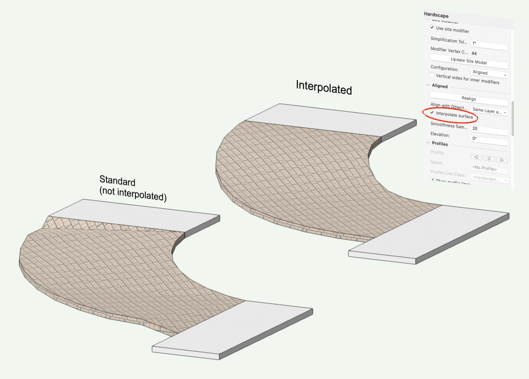
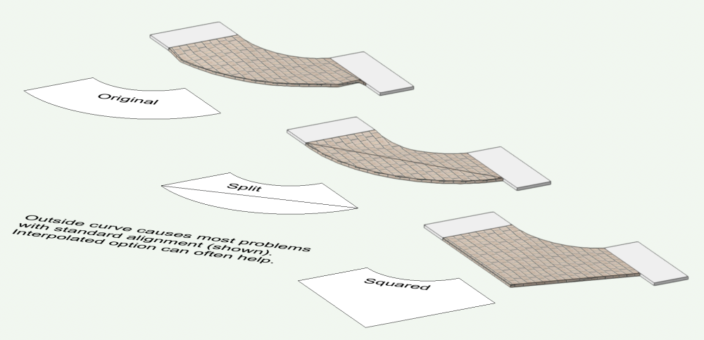
Nothing you did wrong. Curved aligned hardscapes typically have this problem. Several things to try. Interpolate option in the Hardscape OIP is most direct. This option makes the hardscape tangent to the end slabs and smooths the shape between. Result has faceted edges, and the tangency and intermediate slopes may not satisfy design intent. If the hardscape is modifying a DTM, then the Hardscape OIP>Edit Site Modifiers options are available. In that mode, one can create a networked exoskeleton of short grade objects around the outside curve to make desired grade curvature. More grades makes smoother curve, but more file overhead. Another way is to modify the DTM via other types of site modifiers (NURBS are good for this), and place a Landscape Area of correct boundary on the modified DTM area. HTH -B

-
I’m curious too. Seems a great work flow would be to create a library of cabinet symbols in one or more files. The symbols could be arranged separately in the file, or snapped together as demo kitchen(s). Add the cabinet file(s) to the Resource Manager favorites, or to a cabinets folder in the favorites. The cabinet symbols and any demo groupings would then be available to insert as instances into any new drawing. The symbol instances in the new project drawings could be edited without changing the original symbol definitions in the favorites eg change geometry or materials, edit class definitions (color? Texture?), etc. What would be advantages of a reference method? -B
-
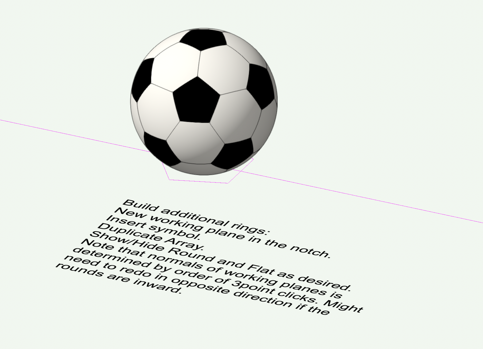
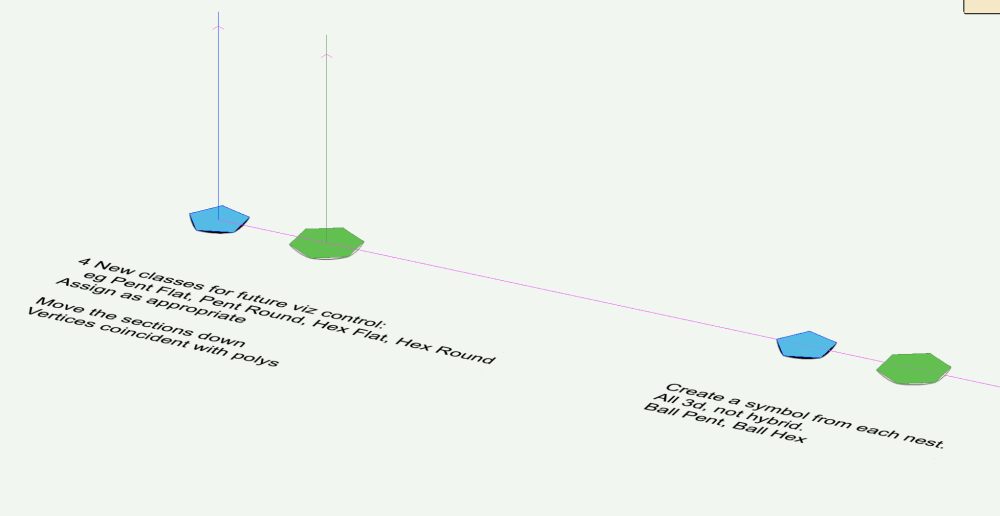
@Kevin McAllister Yes, that would be great. These rotations and other "off plane" operations can trip me up. So I revert to guide objects, knowing that they will work. I think there are multiple ways to accomplish, but they don't always come to mind. For bonus points on the soccer ball, edit the symbols - shell to the concave side for a little thickness. Fillet the outer edges to make the seams recessed. If building another ball, probably means hiding the round classes and working with the flat versions to access the vertices. -B

-
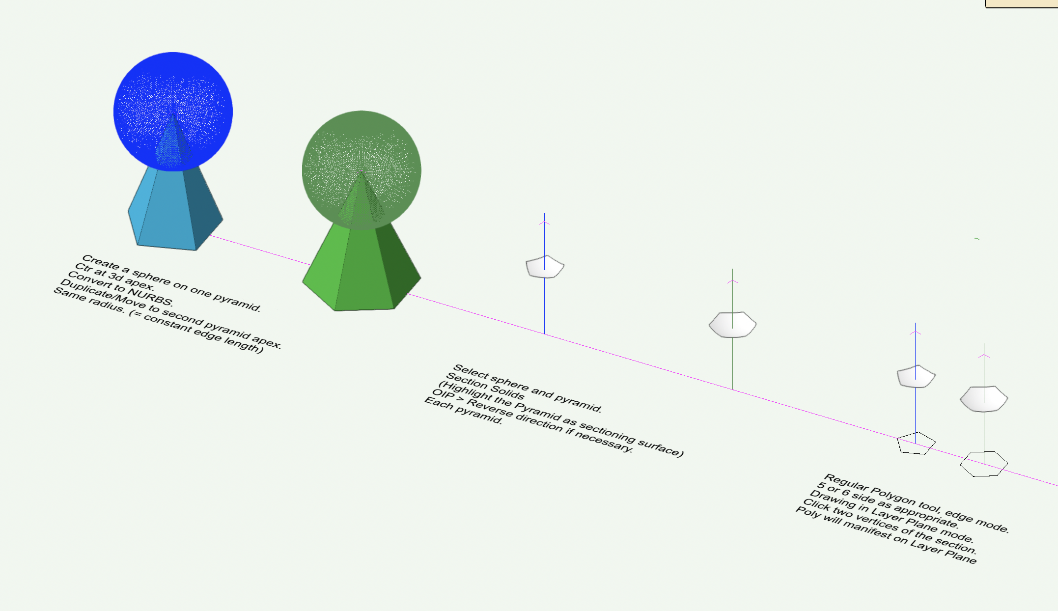
Here is the soccer ball inflated. Similar process, but added steps and options. v2023 file included. -B Icosahedron.vwx


-
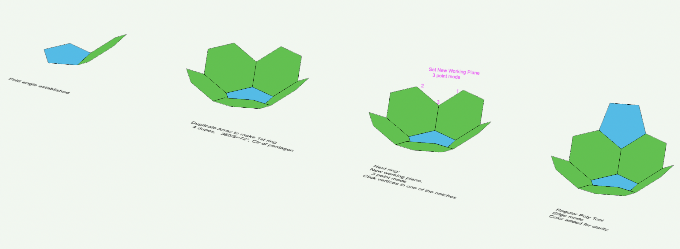
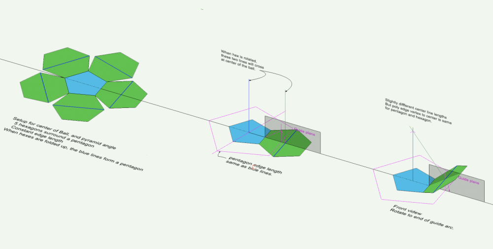
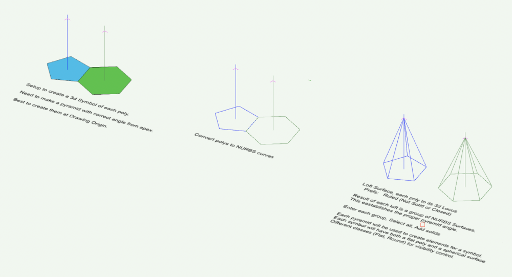
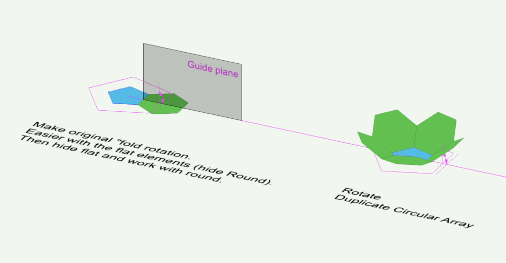
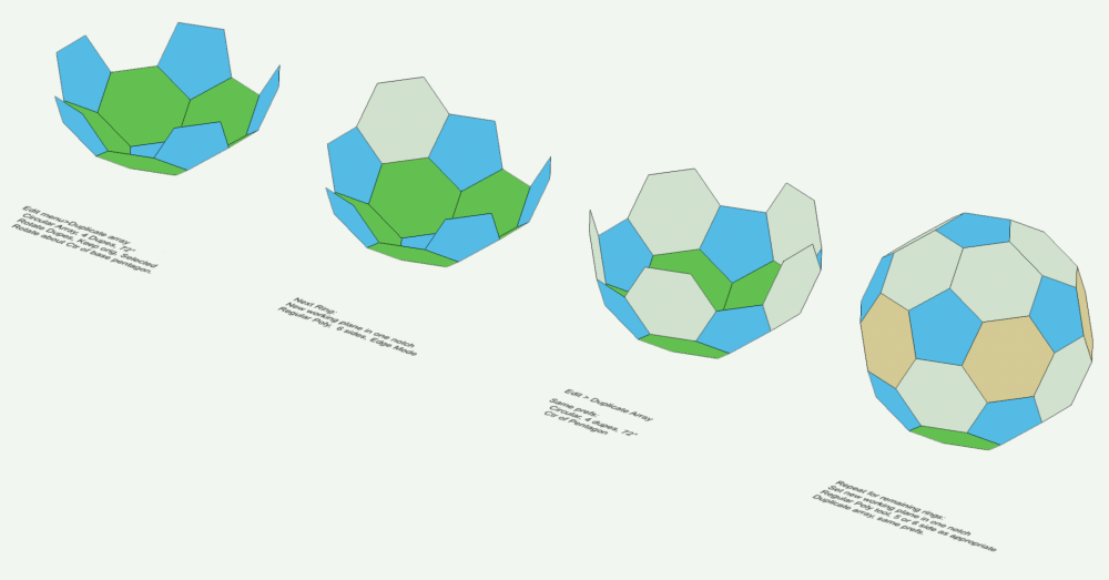
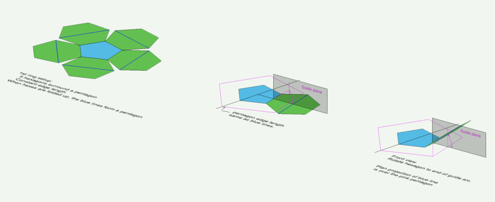
OK, here's the 1st installment. The flat faced version. Main trick is to establish the fold angle of the first ring. See also this: The inflated version is a somewhat more elaborate process. Will include the file. Coming soon. -B

-
Good point, @Kevin McAllister Also, the DTM (eg the original DTM created from all those loci) does not always generate a contour corresponding to the highest source data points/contour. The new DTM might benefit from pasting in a few of the topmost 3d loci from the original data set. -B
-
I really hope there are better answers, but . . . Sort of OK method: Create a DTM from All the 3d loci. In the OIP, choose Edit Existing Contours If needed choose the Selection option in the little tools pane and drag a marquee to select all. Copy this selection. Exit the edit window In a new vwx file, Paste in Place Engage the Select Similar tool with Type as the only pref Click one of the text elevation labels This should select only the labels and exclude the contours. Delete the selection to remove all the labels. Select all the polys. OIP will indicate 2d Polys. But, they continue to have correct z value in Front view. With all of them selected, Modify>Convert>Convert to 3d Polygons. Result is a group of 3d polys with correct z values. Ungroup and use these 3d polys as source data for a new DTM. If 3d polys too dense, select the DTM, then OIP>Recreate from Source Data, Select All, then Modify>Drawing Aids>Simplify Polys to suit. Update the DTM as needed. . . . or . . . Primitive, tedious method #1: Create a worksheet Database row criteria: Type is 3d locus Column forumla: =ZCOORDINATE Column status: Summarize This should present a sub row for each elevation, and display the count of the loci at that z value. To select all the loci at a particular z value, right click the row label (left column, eg 3.1) representing that elevation and choose Select. Now you can send to another layer, or delete, or change the z value of this selection in the OIP, etc. Changing the 2.01m points to 2.00m, or deleting them might be helpful, or might not. Not sure of your intension other than choosing a subset of the available data for creation of the DTM? . . . or . . . Primitive, tedious method #2: In front view, draw a rectangle surrounding the whole lot of 3d loci. This will become a guide object for selection of subsets of the loci. Still in front view, adjust the height (y value) of the rectangle to some small value less than your anticipated contour index value, eg .25m Move this guide up or down (front view) so that it surrounds only the lowest 3d loci Use Move By Points to duplicate the rectangle in y direction at 1m intervals (or other depending what you need to capture). Use each rectangle in turn as a guide to drag a selection of loci within the rectangle. For each selection, Copy/Paste in Place in a new blank file. Depending on needs, and variance of the z values, it might be acceptable to adjust the z value of each selection to a common value. The loci between the selections will be excluded. Create a DTM from the loci in the new file. OK, something like one of these work for you. -B
-
Generating polyline contours at specific height?
Benson Shaw replied to lisagravy's topic in Site Design
@lisagravy @Anders Blomberg @E|FA , et al Oh! Just tried again with v2023. Success! mostly. Did not try this with earlier versions, but might work there, too. Also now using Apple M1 Max, so not clear if equipment makes the difference. Full area DTM with extrude failed. But crop the DTM close to the extrude provides enough geometry reduction to allow the Solid Subtraction to proceed. The Solid Subtraction operation lasted about 10 seconds When placed on the DTM, the water volume did not display because a bit below the surface of the DTM. Probably because the DTM surface gets priority? Or this example is very shallow? Didn't produce any "z fight" in my test. I moved the water up a bit to reveal it. -B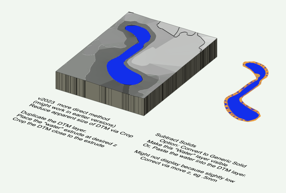
- 26 replies
-
- 1
-

-
- site design
- model
- (and 3 more)
-
The cut and fill view is always on my terrain in 2D.
Benson Shaw replied to Jose Estrada-Arbelaez's question in Troubleshooting
And update the site model. -B -
The cut and fill view is always on my terrain in 2D.
Benson Shaw replied to Jose Estrada-Arbelaez's question in Troubleshooting
The site model settings dialog allows you to designate a display style for the DTM. But the OIP can override that at any time via options in the pull down menus for 2d Style and 3d Style. Try the 2d Contours or 2d Triangle and 3d Mesh, 3d Grid, or 3d Contours. Just the plain ones, not the ones with color features. -B
-
That is called Image Fill. An Image Fill is an attribute, applied to 2d objects via the Attributes Palette, rather than a texture applied to 3d objects via the Resource Manager. Images can be imported as resources, and stored as resources in the resource manager. These resources can be used to create textures for 3d objects, or as sources to create image fills for 2d objects. -B
-
VERY much interesting! Thank you for process commentary and showing results. An apparent preference in the app for prioritizing or ignoring certain elements of the source data requires a curation step (or two). Or perhaps different apps are “tuned” for different expected uses. Good to see reports here matching various apps with use conditions and results. -B
-
Yes, totally agree with @jeff prince and @AlanW - create the DTM with layer elevation = 0. My post above is for correcting if the source data was (inadvertently?) placed on layer with z value other than zero. -B
-
Found one workaround (there are probably others) on similar problem with stakes as DTM source. I found need to remake the DTM, so might be best to work in a duplicate file. Select the original DTM, access Recreate from Source Data, Select/Copy All, exit the edit window. Create or make active a new blank Design Layer of desired scale and z value, then Paste in Place. The contours and other source objects should now report correct elevation, eg relative to the new layer. Or, if necessary, adjust z values en mass via Move 3d. When correct elevation achieved, use these contours to create a new DTM. Depending on how Site Modifiers and other geometry are managed, either Reassign site mod effective layers to this new DTM via OIP>Site Model Settings>Use Site Modifiers On menu>Custom> enable the appropriate layers. Or, correct the z value of original DTM layer, Paste in Place the new DTM into that layer and send the orig DTM to an archive layer (or delete it) and, if needed reassign the effective layers in OIP>Site Model Settings Actually hope there is a better way. -B
-
Maybe????? - The active class is Glazing-Clear. The OIP (render tab) of selected window shows Window in Wall and texture by class. Sooooo, perhaps the window inserted into the Glazing-Clear class and therefore all the components of the ghost windows are now rendering clear. ??? If that's the problem, change the class of the ghost windows to something without texture? Might be best to draw with None class active, or other class with no texture assigned. Assign classes with appropriate textures to the various components of the window. -B
-
Generating polyline contours at specific height?
Benson Shaw replied to lisagravy's topic in Site Design
@E|FA No clue on the adding extruded polys. Might be same issue. @Anders Blomberg et al - I made it work for the DTM, in a couple ways. Both involve making a simplified, smaller DTM from the original to reduce vertex load. Use the smaller DTM to create the Solid Subtraction. Convert to Generic Solid advised. Place the new Water object onto the orig DTM. 1st way: Create a rectangular array (eg 20x20) of 3d loci over the area containing the water. Ungroup if needed. Send to Surface. Send result to a blank Design Layer Create a new DTM using the 3d loci as source objects. Top Plan, draw rectangle or other poly surrounding the water, but inside the DTM. Extrude. Set bottom z inside the DTM. Adjust top z to water surface elevation. Subtract Solids. If OK, probably best to convert to Generic Solid If no go, try again with fewer 3d loci. 2nd way: Increase the DTM contour index, eg to .5m or .25m, or even .125 Edit Proposed Contours (or Existing) Select the contours from bottom of valley to next above the water surface. Copy. Paste in Place on same layer, but leave selected. They are 2d polys. Convert to 3d polys. Ungroup. Send to Surface. Send to a blank layer. I added a 3d poly along mid channel. Elevation .125m below bottom contour. Optional. I also added a rectangle surrounding the whole area, convert to 3d poly. Elevation slightly above top contour. Create DTM from these. Draw rectangle around the water area. Extrude. Set bottom z inside the DTM and top elevation at desired waterline. Solid Subtract. It works if not too many contours. If needed, delete every other one via Edit Source Data and try again. -B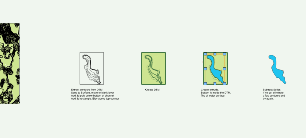
- 26 replies
-
- 2
-
-
- site design
- model
- (and 3 more)
-
Generating polyline contours at specific height?
Benson Shaw replied to lisagravy's topic in Site Design
OK, DTM as subtracting/sectioning object is possible. I just tried it on a very simple DTM - small footprint, few and simple source objects. Subtracting portions of an extrude to fit a hole in the DTM was no problem. There must be some vertex or face limit for such operations. Or some other size related problem that causes a calculation mass which vwx cannot resolve. Might be possible to cut the DTM and/or the lake into segments, make several subtractions, might need to convert to Generic Solids, place the bits together and Add Solids. - royal pain! I will continue tests. Gotta be a way! -B- 26 replies
-
- 1
-
-
- site design
- model
- (and 3 more)
-
Generating polyline contours at specific height?
Benson Shaw replied to lisagravy's topic in Site Design
@Anders Blomberg Sorry to report that I see same error. Seems the earlier posts with Solid Subtraction were in a vwx version which supported the boolean operations. Or some magical moment. I think there is some way to do this. I'm not having success with creating a mesh of the DTM surface and applying that as a sectioning surface. Still some things to try. More later. -B- 26 replies
-
- 1
-
-
- site design
- model
- (and 3 more)
-
Not aware that his is commonly available for DIY photogrammetry, but: LIDAR Site survey aerial data can apparently be stripped to “bare earth” via some magical tech filtering and processing. USGS claims 10cm vertical accuracy. Different layers can isolate and display elevation data for buildings, low veg, trees, util towers, etc. https://www.usgs.gov/faqs/what-lidar-data-and-where-can-i-download-it#faq I think similar lidar data sets are already implemented for UK? EU? Scandinavia? Elsewhere? -B
-
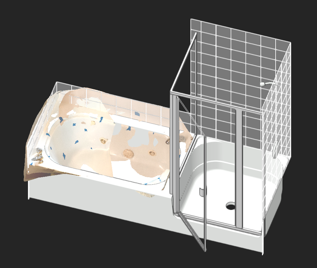
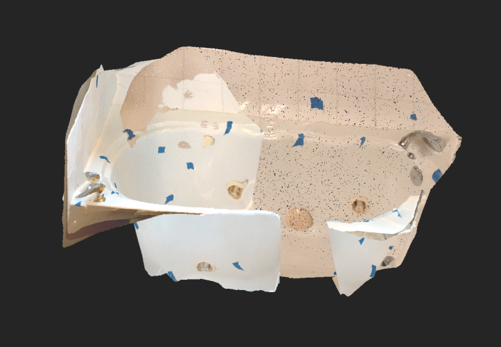
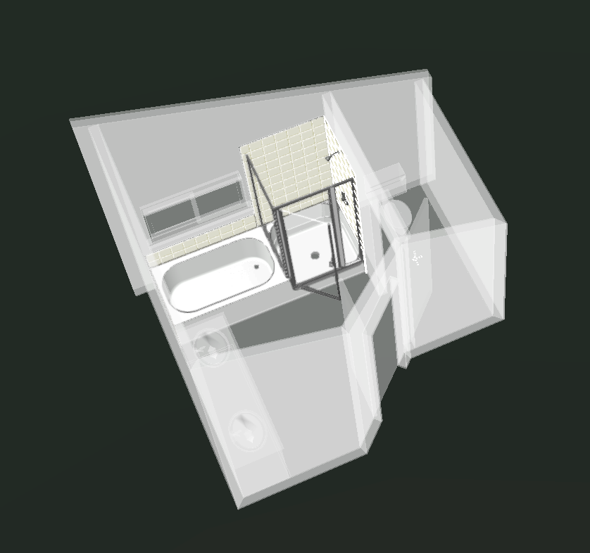
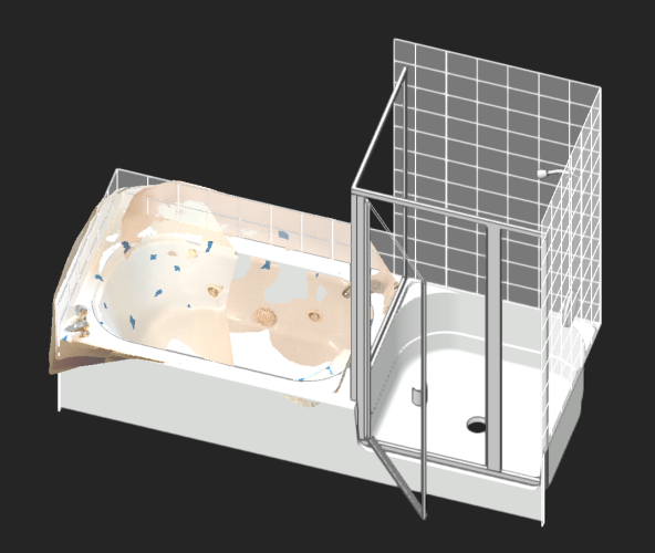
Another limitation, at least without LIDAR, is scans of surfaces which are transparent, or shiny, or consistent color, or of similar color/texture to background objects. I modeled a tub/shower unit via tape measure and lots of fun PushPull, Taper Face and Fillet. It's a strange beast - 8' long continuous piece of fiberglass 5' tub at one end, 3' shower at other. I decided to see how a scan compares using Polycam app (I don't think I will renew it) and my iPhone XS (10) - no LIDAR. The scan processing had lots of trouble differentiating the tub surfaces front to back. The glass shower enclosure with chrome frame caused eruptions and spurs of points representing location of virtual images of reflected objects. As the camera panned and tilted the changing location of the ceiling light and window reflections caused other spurs in the point cloud or just eliminated segments of the surfaces. Scanning with different light (time of day) causes color changes. I was curious whether I could make it work. I stuck bits of tape all over the tub/shower and scanned in small sections. The sub area scans processed reasonable surfaces in some cases, but had to be cropped (eg in the app, or Meshlab), and/or rotated and scaled in Vectorworks (the 6" tile and full screen cursor is very helpful). Then aligned via the tape bits with Move by Points. Constrained spaces almost always require moment to moment camera tilt/rotation to capture the target area (eg in the tub, or in the shower or between the vanity and the tub, etc). This camera attitude change can process a bulge in the point cloud, or produce a cloud which needs 3d rotation to realign to the proper working plane. I never did get some of the sub areas to process. LIDAR would probably help with this (?) and a different app with better processing, and better camera technique. I tried importing LAZ and PLY formats. I prefer the LAZ for only vague reasons. -B
-
@Dave Donley can you elaborate a bit on the 5 meter limit? And whether it is helpful to place objects or points of known size and separation in the scene? Traffic cones, tape “x”s, etc
-
Can you post a vwx file exhibiting the problems? That’s best for troubleshooting. -B
-
Setting to Change Dimensions form Feet & Inches-to-inches Only?
Benson Shaw replied to CW2020's topic in Architecture
Hoping, too much, I think, for this control without using the Dual standard. It’s a longstanding gripe on these forums. But, I think you can achieve your goal with a simple adjustment In a dual dimension’s OIP you have choice to show both dim modes (side by side or over/under), primary only, or secondary only. Sounds like you have pref for Both, which shows feet&inches plus, in brackets, inches (ya know, dual). In the OIP dropdown, choose instead the show Secondary only. This disables/hides the Inches&Feet (primary) part. If you made the conversion for the selection, and all your dims show both modes, select all of them again, and change the OIP pref so that only the secondary (Inches) is displayed. Or did i miss your intent? -B -
Setting to Change Dimensions form Feet & Inches-to-inches Only?
Benson Shaw replied to CW2020's topic in Architecture
Several things control this. 1. If you want ALL standard dims in the drawing converted to inches only (or to any of the other options): Open the File Menu>Document Settings>Units In the resulting Units Dialog, choose Dimensions (top item) from list on the left side. Near top, click the Units dropdown menu and choose Inches from the list. Result will be conversion of all standard (not dual - see below) dimensions in the drawing. 2. If you want to change a selection of dims to Inches and leave others as Feet and Inches, you need to set up and apply Dual Dimensions (bit of a slog, but you will get there): First - Set up Dual Dimensions for the drawing as follows: Open the File Menu>Document Settings>Units In the resulting Units Dialog, choose Dual Dimensions (2nd item down) from list on the left side. Open the Units dropdown (I think it defaults to mm) and choose Inches. Adjust your rounding preferences as desired. Click OK to accept. Can be edited later. Sorry, “dual” is as high as it goes. No option for triple other multi dim combos) Next - In the drawing, select the dims you want to change. In the OIP>Units menu (near top)> choose either of the Dual Dimensions options (Stacked or Side by Side). Further down in the OIP>Dual View menu>choose Secondary Only (defaults to Both) Below that click the Sec button (secondary dim) and adjust precision fields as desired. The selected dims respond to the new pref. OK, post back as needed. -B -
Hard to say from the image. but . . . A blue/cyan line kind of weaves in and out of your terrain. If that is a Grade Limits object, which often displays as cyan, you might benefit from deleting the complicated shape and redrawing as a rectangle surrounding the terrain boundary, or even to enclose all the other objects which extend beyond the terrain (crop?) boundary. Assign to existing. Update the terrain. Good luck! Post the file if possible. -B