Tom W.
-
Posts
5,073 -
Joined
-
Last visited
Content Type
Profiles
Forums
Events
Articles
Marionette
Store
Everything posted by Tom W.
-
I thought the advice is to always rebuild your custom workspace from scratch each year rather than migrating it over (to exclude the risk of it becoming corrupted). It's a real pain to do but I was told it's not worth the risk...
-
Yes I think it just gives you a written record to refer back to when you manually recreate the workspace...
-
I'm pretty sure the text file is just for reference + can't be imported as such but I'd love to be wrong on that... I don't find it enormously useful to be honest. I keep screenshots of my workspace as well + find these more useful when it comes to recreating it.
-

Various issues, lot of crashing no clear reason, high memory usage.
Tom W. replied to Blinkglitter's question in Troubleshooting
Does this apply to XS as well or just full interiorcad? I just changed from demo version XS to proper paid version a few days ago + it says I'm on version F4.1... Should I be looking to update...? How? Thanks -
How to add a hatch to the Top/Plan View of a symbol?
Tom W. replied to Darin K's topic in General Discussion
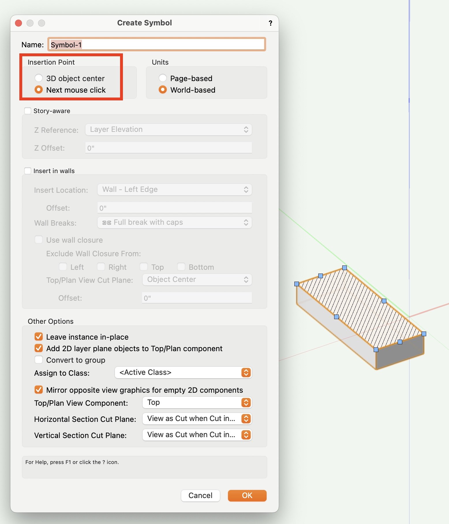
When you create a symbol you have two options for setting the insertion point: 'Next mouse click' allows you to place it precisely where you want + this is the option you used. '3D Object Centre' (or 'Plan projection centre' if you are in a Top/Plan view) does it automatically + places it in the centre of the object. Just to explain what the circle/cross symbol was!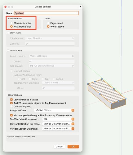
-
How to add a hatch to the Top/Plan View of a symbol?
Tom W. replied to Darin K's topic in General Discussion
This isn't correct. See attached. I just selected both objects then went to Modify > Create Symbol... + it gives me a 2D/3D Symbol. You see the 2D geometry in Top/Plan view + the 3D geometry in 3D views. Hatch Issue File_TW.vwx -
How to add a hatch to the Top/Plan View of a symbol?
Tom W. replied to Darin K's topic in General Discussion
Not sure what you've done. You need the 3D object + the 2D object selected at the same time then run 'Create Symbol'. It should create a 2D/3D Symbol if the 2D object is at Z=0. Post the file if you like -
How to add a hatch to the Top/Plan View of a symbol?
Tom W. replied to Darin K's topic in General Discussion
Does it say '2D/3D Symbol' in the OIP or '3D Symbol'? Sounds like the latter to me. The rectangle needs to be at Z=0 when you create the symbol not raised to the top of the extrude. Then a 2D/3D (hybrid) symbol will be created -
I think Gray Others is fine in Top/Plan but I always disable it in 3D I find it pretty useless there. I use a script assigned to a keyboard shortcut to toggle between the settings because it's not practical going into VW Prefs to do it each time. But I agree with you it would be good to have a middle option between fully visible + completely greyed-out as you can forget you're in an edit mode when everything else looks completely normal!
-
Doesn't disabling 'Gray other objects' help? In VW Preferences.
-
No. You can grey the background objects but that's it.
-
How to add a hatch to the Top/Plan View of a symbol?
Tom W. replied to Darin K's topic in General Discussion
Sounds good to me. Or you can draw the 2D shape, copy it, extrude it, paste in place, select extrude + 2D shape + create symbol: with both a 3D object + 2D object selected a Hybrid symbol will be created in one action. -
How to add a hatch to the Top/Plan View of a symbol?
Tom W. replied to Darin K's topic in General Discussion
If you Ungroup the Auto-Hybrid in a 3D view it will return to being a 3D symbol. Then right-click on it + chose 'Edit 2D Components' to add Top/Plan geometry. In the Top view edit mode you can right-click + choose 'Generate 2D From 3D Component...' -
How to add a hatch to the Top/Plan View of a symbol?
Tom W. replied to Darin K's topic in General Discussion
I would use a Hybrid Symbol rather than an Auto Hybrid. This was the other option that @mjm gave. You will have a lot more control over the 2D representation, both Top/Plan + other views. If you want, you can include different geometry in different classes + show different things at different times e.g. a schematic representation, a realistic representation, text, etc. -
Site modifiers and Cut and Fill calculations
Tom W. replied to Christine Mulinder's question in Troubleshooting
It sounds to be like you're virtually there with the 3rd image if it results in only 0.895m3 of soil needing removing from site. As far as I understand, the Spoil Pile Modifier is what you'd now use to get rid of that 0.895m3 by spreading it somewhere on the site to lose it. That is why in your 2nd image you have ended up with a fill value of 28.03m3 + a cut value of zero: because in effect, using a spoil pile you've just come along + spread a load of soil over the site. Alternatively can you raise the elevation of your pad modifier slightly to reduce the 0.895m3 you currently need to remove from site? Raise it incrementally until there's zero left over? -
Black frame/window in 3d viewport. What is that?
Tom W. replied to Laukutis's topic in General Discussion
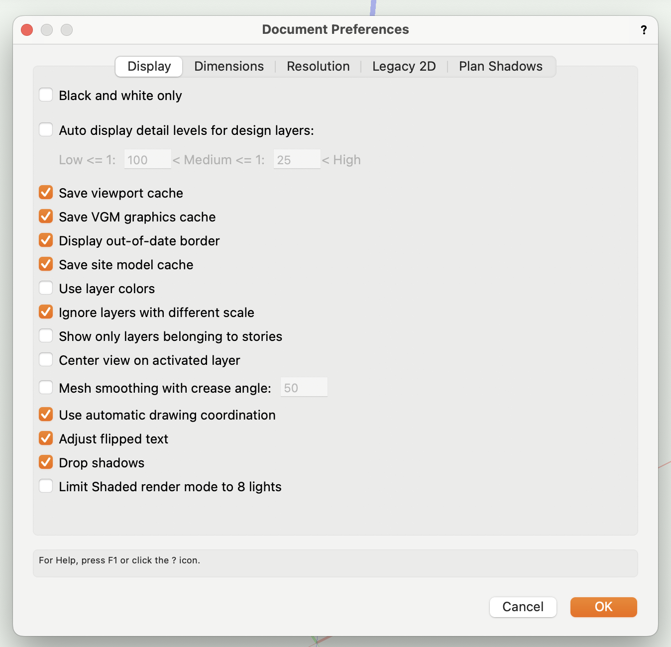
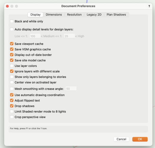
It only displays as an option in the Display tab if Enable Legacy 2D features is checked first. But if the crop is displaying in the drawing area then presumably Legacy 2D features is enabled... Legacy 2D disabled: Legacy 2D enabled:
-
That sounds completely plausible. And the fact it's a text field + the entries in the VW hardware sets (which I've never really looked at before) all say '1 1/2 Pair' like you say so I guess it's not set up to provide a total count of all the hinges in a project... Be interested to see what your report looks like @Christiaan, or anyone one else... How useful/practical is it reporting on Hardware Sets generally?
-
I saw Hardware Quantity - and it's present in the 'Create Report' dialog as well as per @Christiaan's screenshots - but I also assumed we were looking for Hinge Quantity. I have never reported on a Hardware Set before so is that what 'Hardware Quantity' returns: the number of hinges...??? I assumed it returned the count for each type of hardware set in the file. So a door could have one hardware set comprising a pair of handles + one lock + a pair of escutcheons or whatever but also perhaps two, three or four hinges depending on the size/weight of the door... How do you report how many hinges per door?
-
My User Origin is always in the same place: the 0,0 point for the British National Grid. I never need to move it anywhere else.
-
But am I right to say that you will only see lines as they will print/publish if you also have 'Zoom Line Thickness' enabled?
-
You need to draw it in 3D Line Mode to begin with. Then you can use 'Height Point 1' + 'Height Point 2' in the OIP to adjust the elevation of the start + end of the fence. Or draw a Polyline in Top/Plan, send it to surface (it will convert to 3D Poly in the process), then snap to the 3D poly as you draw the fence (in sections) in 3D.
-
Hmm can't even find it with Pat's hidden PIO field script...
- 7 replies
-
- 1
-

-
- hardware
- worksheet function
- (and 2 more)
-
The User Origin is represented by the red/green (+ blue) axes. So as long as 'Show 3D axes' (+ 'Show 3D Z axis') is enabled you can see where the User Origin is. e.g. Or you want something in addition to this?
-
You've obviously not used Slabs then... 🙂
-
Yes the only way to apply textures to Door components is by class. But another option - and what I do most of the time - is to use Custom Leaves. This way you can control the texture mapping on the leaf at least yet still benefit from most of the PIO functionality of the Door object.