Conrad Preen
-
Posts
1,023 -
Joined
-
Last visited
Content Type
Profiles
Forums
Events
Articles
Marionette
Store
Everything posted by Conrad Preen
-
Not sure that I was wondering about that... 😉 Anyway we have added this to our list of stuff people would like. Best Conrad
-
Hey @elc, which version are we talking about? Nowadays you don't need to edit text files, all that is done in the ConnectCAD Settings menu and you don't need to restart Vectorworks. Conrad
-
Hi @BeamerBob I'm not sure what your "Restrictions menu" is ? It isn't part of the standard ConnectCAD workspace. The Tech Pubs have put a lot of work into the online help. I think that would be a very good starting point especially when upgrading. Best Conrad
-
Hi @Rune Røsten Yeah you're running into the things we have to do in order to have easy 2D drag and drop for populating racks. Equipment items need to draw in a 2D front view when they are mounted in a 2D rack in top/plan, but draw in 3D when they are free-standing. This means we are fighting the logic of Vectorworks a bit. Unfortunately we don't have a Front/Plan view available for rack elevation drawings so we have to make do with Top/Plan. And that means acrobatics... Our lives as programmers would be easier if the entire rack workflow was 3D, but your life as a user would be harder. Any 3D placement operation involves adjusting the view first, or going into a mode to isolate the equipment and rack before placing. We've kicked this around the block a thousand times and still 2D drag and drop comes out unbeatably fast and intuitive. Bottom line here - there isn't a lot of demand for 3D-modeled connectors. Most designers seem more concerned with getting their projects finished earlier rather than investing time in this kind of detail. Not that you can't do it - just be aware that it may not be possible to automate it. I'll keep this in mind and expect a way to hide this text in a future version. Best Conrad
-
Interesting! I tried converting those fairly complex sockets into symbols and then replacing the four groups (which are the same geometry) with symbol instances. This would be the right way to go anyway to reduce file size. When I did that the new symbols immediately landed in their correct places. Obviously that's just a workaround and as Niko says we will investigate. Generally when you pull in models from other software it is a good idea to factor it into symbols if you have the time because it can dramatically reduce file size, memory use etc. Best Conrad
-
Good morning @helleMOMENTE and good week! Nice to see that even with some difficulties there is still a way for you to get what you want !!! As you infer we are still working to improve the merge between Spotlight cable tools and ConnectCAD. We are in a much better place than we were a year ago, and next year we will be in even better shape. When you are thinking about cabling design there is this triangle: Schematic circuits Cable paths Physical cables In most situations at least one of the three is redundant. For the purposes of ConnectCAD we infer physical cables from the cable path + connectivity. Spotlight works with the physical cable and uses cable paths as an aid to drawing them. Since the Spotlight team develop the Cable object it would be a good idea if you posted you feature requests ( including interactions with ConnectCAD Equipment objects ) in the Spotlight section of the forum. We will of course pass the message on, but it carries more weight if it comes from you. Best Conrad
-
Connectors with more than one signal type.
Conrad Preen replied to Rune Røsten's topic in ConnectCAD
Hey @Rune Røsten a) don't get hung up on what signal type to use - you can always add your own special types b) if you are breaking out from these connectors to other devices i.e. audio going one place - data going another you can connect two circuits to the same socket and then in the circuit, override the signal set by the connect tool in the object info palette. Hope that helps. Conrad -
Hi @helleMOMENTE That is as very good summary of the workflow I must say. Except that there is nothing special about the Rack Elevation layer - it can be any layer of suitable scale. In your case wouldn't it be worth creating a schematic anyway and utilising the automatic assignment of circuits to routes thru the cable path network? Effectively treating circuits as physical cables. Seems to me this would probably save you time. Then you can get a nice report of your cables (circuits) with their start and end points. And if you need to override the routing then you draw a Spotlight Cable (following paths if you want) and assign its RunID in the Circuit.Cable popup. My 2c worth. About you points/questions allow me a short digression into human physiology (you'll see why). We have a branch of the Vagus nerve that joins the back of the throat to the brain so that shouldn't be a very long run right? Well in fact it goes from your throat down the neck into the thorax around the aorta and back up to the brain. Not exactly optimal - and in giraffes it's frankly ridiculous. So why is this? Well back when our ancestors were fish this was a reasonable route to take. Much the same applies to software. It evolves towards local maxima. Radical re-design proposals like "Reroute The Vagus Nerve" meet objections like "it's been working fine for millions of years" and "what's the benefit to the animal?" or "you really wanna re-time half the brain?". ConnectCAD and Spotlight started from different places working on vaguely-related cabling features. Last year after walking a total of about 70km and thinking about it I managed to achieve a fairly reasonable merge of functionality. All that you say is of course true but at least we are in a much better place than previously. I hope to get even better interoperability in forthcoming versions but you must appreciate that this involves bringing together diverse teams on different schedules. You input is a valuable part of getting things moving. Conrad
-
Does that work? Conrad
-
@helleMOMENTE that's already been asked an it's on our radar! Expect a helpful menu command soon 🙂 Equipment items question - that looks like a something got missed. I'm filing a report now. Thanks for letting us know. The Wavy Line - again good point - we are looking at revamping the ConnectCAD classes so yes, we'll certainly take that into account. Thanks Conrad
-
This is nice @Ben59 just be aware that we will be re-organising and renaming the classes that ConnectCAD assigns by default. This is mostly to do with giving you more control over the visibility and appearance of the internal parts of ConnectCAD objects. From what I see it looks good. @Pat Stanford Thanks for sharing that script! I really want to encourage everyone to take control of their Vectorworks workflow in this way. The journey begins with hacking around an existing script. Conrad
-
Hi @sbecraft Schematics are essentially not-to-scale drawings. There is nothing in a schematic that represents a physical dimension in the real world. So in a way the layer scale for these is irrelevant. You can print them out at any size you want using viewports on sheet layers. So it would be good to know specifically what you want to accomplish when you say "if a document I imported from VW2021 is at a scale I don't want". Since layer scale doesn't usually matter, is it the text size in relation to the socket spacing that is the problem? A picture will help me a lot to understand and advise you. Best regards Conrad
-
ConnectCAD / Spotlight - Cablepath changes Design Layer when Cable is drawn
Conrad Preen replied to FKA's topic in ConnectCAD
@helleMOMENTE Hi Florian, I just checked and can confirm that this is fixed in a forthcoming service pack. Best Conrad -
Definitely sold me the idea! It is on the roadmap.
-
This idea is gathering votes like crazy! We'll definitely look into this. Conrad
-
Here's a handy script for selecting only equipment items that have no device. Open source for you to play with and modify. Enjoy Conrad CheckOrphanEquipment.vwx
-
A question about asking question on the forum...
Conrad Preen replied to tspilman's topic in ConnectCAD
Hi Tim, We've already talked, but I'm answering here for others to see. Speaking for the development team, we check in here regularly and try to respond time permitting. This forum is a great way to let us know about features / capabilities that you are missing. And we do implement a lot of the requests. What this forum is not good at is providing those simple "how to" answers. As you have noticed. Often the answers are in here, it's just that they are buried deep and the search is pretty useless. What I've found with forums is that Google does a way better job of finding stuff if you type in a normal "how do I do this?" question restricting the search to this site. Needless to say I have already raised this in the company but if you add your voices to a campaign for a How To section this will help a lot. Conrad -
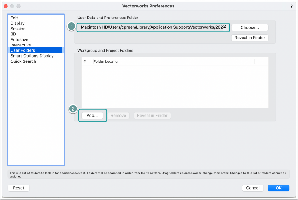
Hi everyone To share device symbols all you need to do is set up a Vectorworks document in a shared location on your office network, and use the Resource Manager to copy any new symbols you create to that location. Most people set up a favourite in the Resource Manager to easily access the shared folder. But let's go a bit deeper because you'll also want to share connector types and signal types etc. ConnectCAD follows the general Vectorworks paradigm of user folder, (workgroup folder), and app folder. Let me explain: Our plug-ins look for resources they need first in the user folder path (1) and then in any workgroup folders that you can add (2) in the preferences dialog. If the resource isn't found the default in the application folder is used. User folders and workgroup folders mirror the directory tree of the application folder so as a CAD manager you need to set up the user folder content the way you want it, then copy the user folder contents to the shared workgroup folder on your network. Then on each workstation add the user folder path in the Vectorworks Preferences. Hope this helps. Conrad
-
@Thomas K.Ok these examples are great - one question - generally speaking are these cabinets using standard rack unit mountings (44.45mm) vertically? I ask because we've also had a request to support generic cabinets without U mountings. Just want to get the whole picture. Not sure I can promise something immediately because the day still has only 24 hours but it's going on my list ! Conrad
-
Kein Problem! Vielen Dank!
-
Hi @Daniel K Can you point me a link to the manufacturers of this 9.5" rack? I'd like to learn more about it. Conrad Preen Product Planner - ConnectCAD
-
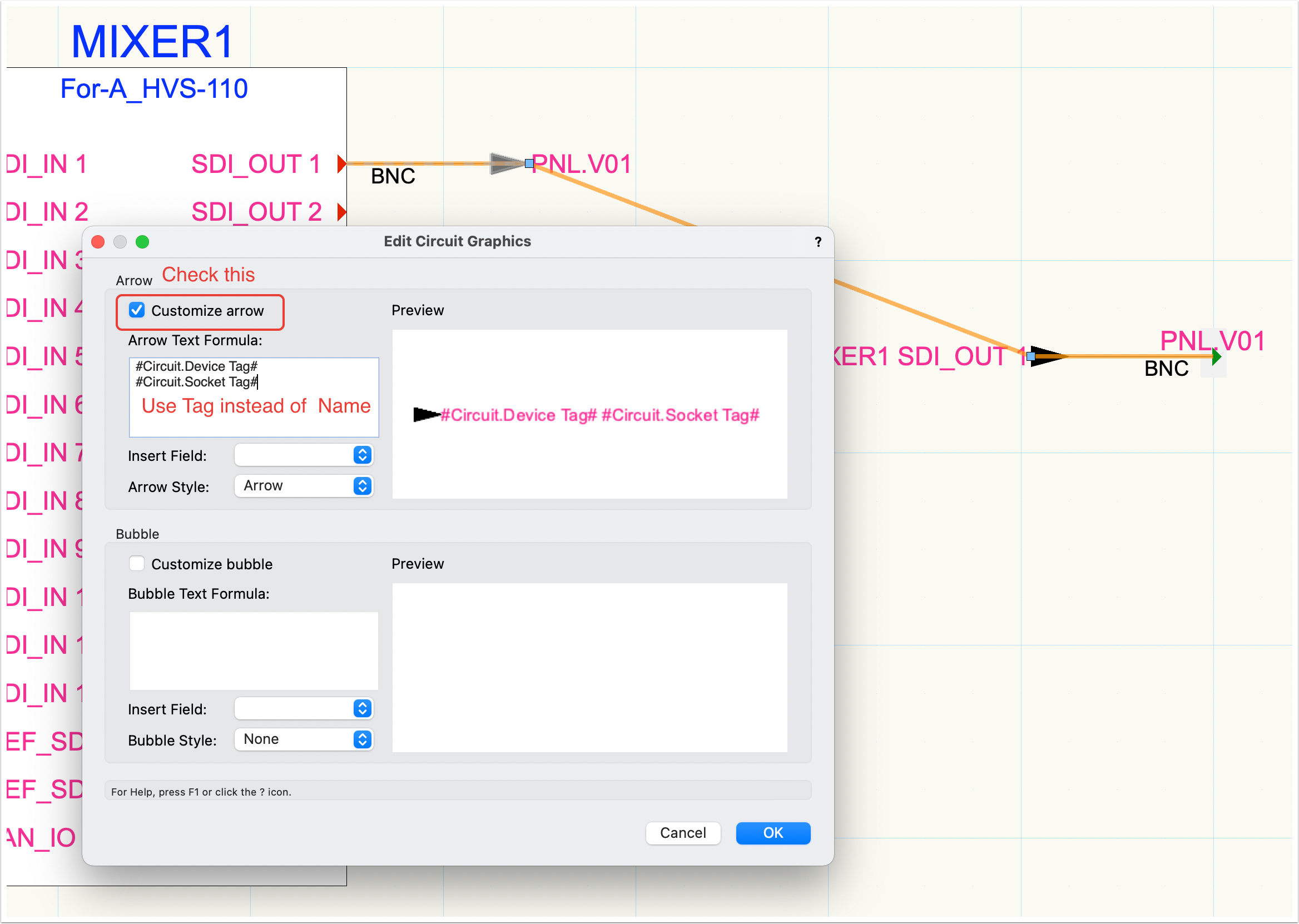
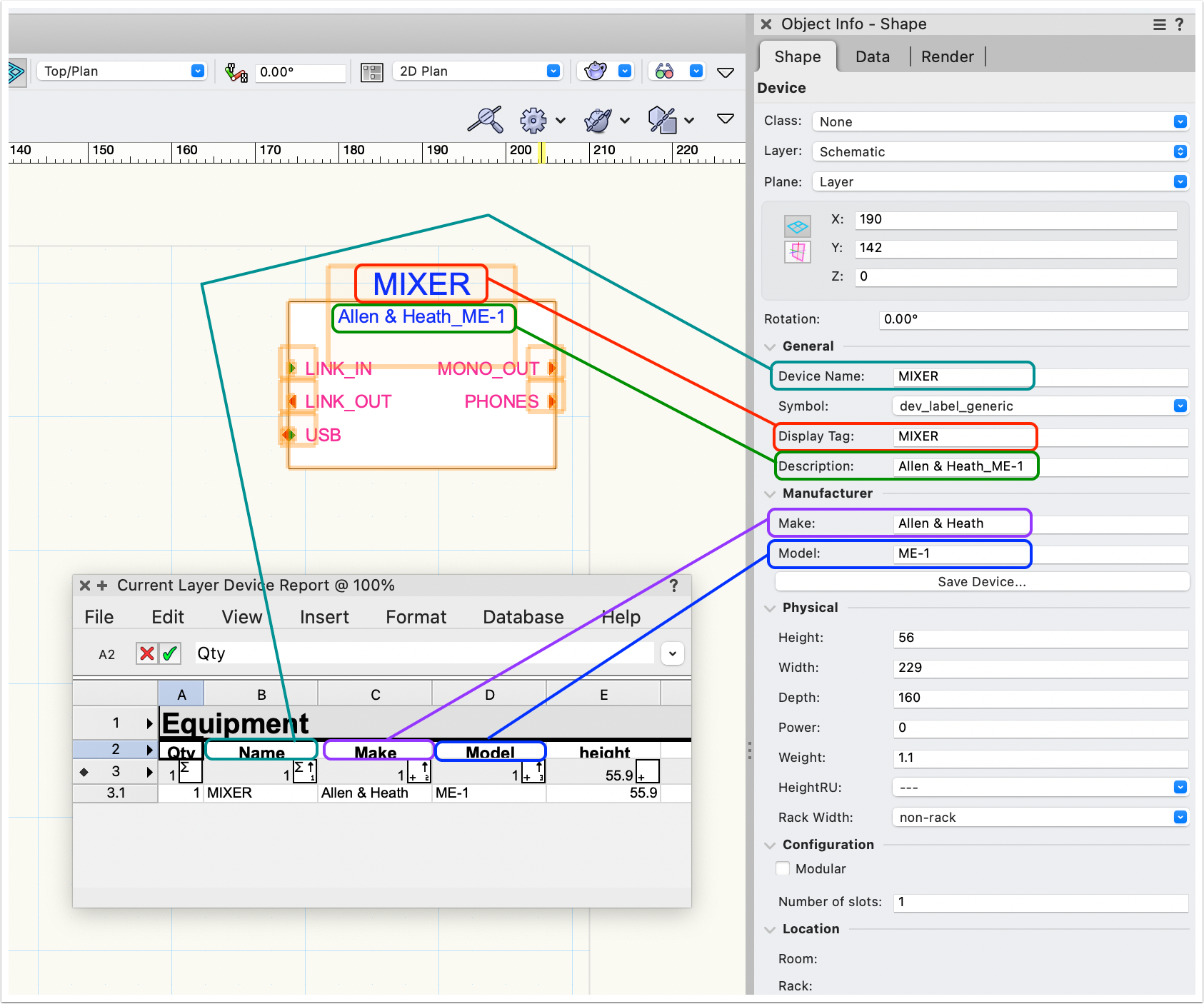
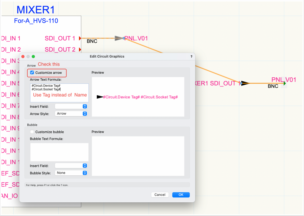
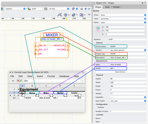
@ChollyO You could set the Display Tag parameters of your slot devices to empty and use the Description parameter to show the slot contents. Here a quick diagram of what params show on the drawing and what go in reports. On rack elevations you can control the text sizing from the Font menu though you may have to set the size really small because of scaling. C
-
Hi everyone! In system schematic drawings you can model these kind of modular systems where you have a main unit and plug-in cards in the way that @ChollyO shows above. The cards are separate devices that you can group together with the main device to make them easy to move around. Circuits understand that devices can be inside groups. So for schematics there is a solution that is fairly elegant without getting into manufacturer-specific details. On rack elevations we have rack frame objects that can be set up with an array of slots horizontally and vertically. Rack frames relate to schematic devices through their names just like equipment items. So you would give the rack frame and the main unit the same name in this case. That is what ConnectCAD can do as things stand in terms of placing modular equipment. The rationale of rack elevations has been that you basically need to get the cables to the right rack U with enough slack to connect them and the installer does the rest. Don't forget that Vectorworks itself gives you the ability to create drawings of specific equipment configurations in as much detail as your patience allows. @CharlesD I am interested in the idea of being able to create named card slots inside equipment. This is attractive both as a way of allowing more detailed modelling of physical locations and also as a way to merge rack frames into equipment items giving a cleaner data model. As I've indicated above these are topics we are considering and working on. But like everyone else in the world we have to maintain focus and work with finite resources. Our schedule is pretty full this year but if I can fit it in I will let you know. So this is the current state of play. We had not conceived of the rack elevation as being the primary detail drawing with schematics derived from it - that's an interesting workflow! I'll be thinking about that. Best wishes to all. Conrad
-
@Theo D Hi Theo! Happy New Year! Not sure this question belongs in the ConnectCAD section... Conrad
-
I would not recommend editing that text file. It is very easy to get wrong and have the Device Builder stop working. So if you absolutely have to do this then at least make sure you keep the original in a safe place first. It is so much easier to modify the device symbols created by the Device Builder to have sockets ordered and grouped EXACTLY as you want them. And then just drag them on from the Resource Manager. As you build up symbols for the devices you use frequently you can put them in a shared document, set that as a favorite in the Resource Manager and have it always accessible. That way your drawings can always have that great "Z Pete" look! Happy New Year! Conrad