


tspilman
-
Posts
33 -
Joined
-
Last visited
1 Follower

-
Linking Record formats to referenced Excel worksheets
tspilman replied to Tim Harland's topic in General Discussion
Hi @Luka Stefanovic , in this video (at about 37:26) you talk about advanced features of the excel import and linking the fields with a schedule. Is there any documentation on how you achieved this? I cannot find any way of getting this to work. Also, at 36:49, you show a table layout and a worksheet - these appear to be linked; with data tags attached to each seat (this seems like an obvious way to take advantage of the excel import capabilities). Are the graphic layout and the worksheet linked? Or would you have to make changes in excel / VW to update the spreadsheet, then also have to go into the drawing to update the graphical representation? (I would assume they are linked - or at least there is a road map for them to become linked in the future) If there is support for this, please could you link me to it? I'm struggling to find the appropriate resources within the VW help system, so could do with some guidance on what would have been a successful search. Thanks in advance. -
Hi all, I am trying to understand what the uses are for the linked excel settings in 2024. This seems like it has potential to be a really powerful tool, but I cannot get it to work. I have previously used the 'Export Lighting Device Data' command to create a text file, then imported it into excel, before modifying and re-exporting for import back to VW (useful, but problematic as there are lots of opportunities for data to become lost / it's a really clunky process). I was really hopeful that the linked worksheet would really streamline this process; however, at the moment I'm really struggling to see what it adds - I cannot understand how to tie the worksheet data back into the drawing. The option to place a worksheet into a drawing appears to be no more useful than dropping a bitmap of the cells on the page. I would like to modify the data in excel (where I can use formulas as well as sorting and filtering data) and then push it to VW. I would also like the changes I make in VW to be pushed back to the spreadsheet so everything is up to date. As I mention, I have successfully linked excel with the worksheet in my document, but I cannot work out any way of linking a row / individual cel in an imported worksheet back to any item in the drawing; never mind see any way of doing this for several hundred lighting fixtures. I have seen mention of using a fixture schedule, then referencing the imported worksheet. That sounds like a step in the right direction, but A- I cannot get any formulas in worksheets to behave at all (they just show up as text - they never work), and B- I cannot see how to automatically link several hundred fixtures back to these rows of data. (I would have hoped to see an option like __UID where I can hard reference the worksheet data then make any changes I like. I have watched some VWUniversity videos which allude to some features that may do what I want, but I cannot find any explanation of how to actually do it. Can any one help? (If this does exist within the extensive help resources, please could you direct me to it - I cannot get the hang of how to find stuff in there) Thanks in advance.
-
Hi all, How do I get 'compare to inventory' to work in 2024? I have created added a venue's equipment list to the inventory and equipment list, and I have correctly set up the source in symbols and parts (In use and remaining counts appear to be correct). However, when I create an equipment summary, and select 'compare to inventory' I just get #/0 for each line item. I cannot work out what I am doing wrong. Any suggestions? TIA
-
Great! Thanks Tom. I knew that would be simple - just a case of finding it (it's obvious now)
-
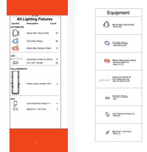
Hi all, I've recently been introduced to Graphic Legends, but I'm having some trouble creating an instrument summary; The following screenshot shows a viewport of my existing instrument summary, and next to it the Graphic Legend I am trying to build. 1, the border. I've tried to edit the cell layout, but I cannot find a way of reducing this massive dead space. any suggestions how I can deal with this? (I really don't want to have to build this then use a viewport to scale this down - that seems really silly and I am SURE there is a solution somewhere) 2, mode I', including the following dynamic text definition to pull fixture mode and DMX footprint, but I want it to show *JUST* the mode. So the sharpy would show 'VECTOR (20)' instead of restating the fixture type as well. (this may end up being a user field due to inconsistencies in the way fixtures are labelled) #Lighting Device#.#Fixture Mode# (#Lighting Device#.#Num Channels#) 3, fixture count I am sure this is a simple one, but I cannot find how to display the fixture count for each in my source; any suggestions which field / settings can be used to calculate this? 4, scale per entry (the border thing above will probably resolve this as it is not an issue with the more compact instrument summary) is there a way to set the scale per entry, so I can reduce the size of the follow-spot? Also, is anyone able to direct me to some pre-existing styles I may be able to edit instead of building these from scratch? (the ones in the software aren't really relevant to spotlight) Thank you all Tim
-
Hi all, I'm not sure whether this is a bug, or an issue with settings somewhere on my machine; but I cannot get the temporary pan tool (activated by spacebar) to work. If the cursor is moving when I press spacebar, the 'hand' icon temporarily appears then immediately returns to the previous tool. Any suggestions?
-
Ok, Thanks Scott. (please move this if it should be posted somewhere else) Is this looking like a SP1 fix, or is this further away? - is there a JIRA report for this so I can keep an eye on its progression? It also appears I had an issue where updating cable parts after adding cables to a drawing caused all of the selected parts for a cable configuration to be removed (although I have been unable to re-create this). I do note that if I change the spare cable requirement in cable preferences, the selected parts do not update until I bump the location of the breakout. Is there any way to force selected parts to re-calculate? there also seems to be an issue caused by the following: - place a fixture, distributor & run a feeder between - open cable configuration to confirm selected parts - move the fixture - open cable configuration to confirm update & ok out - ctrl+z to undo move - open cable configuration to confirm update & ok out This causes the cable route to jump back to the pre-undo location (although opening cable configuration again shows the correct length of selected parts) the only way to resolve this appears to be to bump the fixture - causing the cable route to jump back to its correct location. finally, spotlight>cables and power planning>create cable report appears to be a one shot command; I am unable to update the worksheet. Is this operating as you would expect?
-
Hi all, I've tried again at this and it still appears to not be working. I am using the resource "Distro Socapex-19>16A (1phCEE) Breakout 1m" as the socapex breakout. When I run a feeder (or jumper) cable from the distributor item to a fixture, it calculates the total length (including any spare as specified in cable preferences. I do not see any way to reduce the cable length with respect to this (or a staggered breakout). Any suggestions how to make this work would be appreciated. TIA
-
great! thank you
-
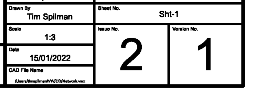
Hi, apologies if this is covered elsewhere.. When I publish a set of drawings to PDF, the text in the title block is of a really low quality (see image) I've checked this with exporting PDF; it appears the publish command is rasterising the text - If I enable this option in 'export pdf' settings, I get the same low quality issue. How do I stop the publish function from rasterising the text? (I can deselect this in the export menu, but not publish menu). Any help is greatly appreciated.
-
Thank you
-
Hi, anyone know whether this is possible? I have created my network schematic, but now I want to go through and set the appropriate VLAN for each LAN connection. I have gone into settings and created a custom bubble which shows the signal, but I do not see any way to apply this to *some* of my connections. Likewise, I only want to apply this to the relevant cables, and don't really want to be going in and out of the default circuit graphics to add / remove the customisation when I switch between power / LAN / DMX. Any suggestions would be gratefully received. Ta
-
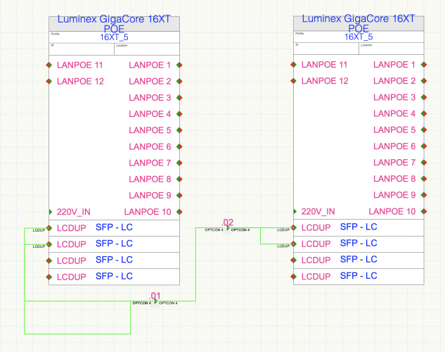
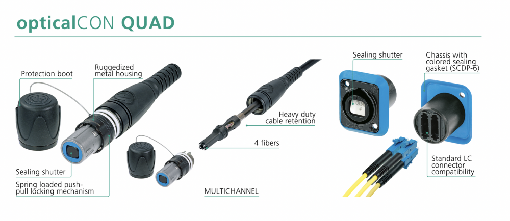
Hi, I am interested in how people are dealing with multicore fibres. The general setup is as follows: Luminex Gigacore 16XT with 2x SFP - LC cages this provides 2 sets of 2x LC fibres 2x pairs of LC patch cables, linking to Neutric OpticalCON panel mount connector this takes the 4x LC fibres and combines to the OpticalCON layout (this is a passive panel mount connector, not a device) Quad Core cable to go where it wants the reverse to get back to a switch. I believe this is a fairly standard setup. I am having trouble understanding how to present this in schematic view so that it makes sense. I've tried to represent this in a screenshot. My questions are as follows: Will this 2 into 1 connector work? I cannot work out how to define the connector on the other side of the panel (take '.01'; the cable to the right should be OPTICON; the cable to the left should be LCDUP) (there may well be more followup questions, but any help with this part will be greatly appreciated) EDIT: screenshot of the panel mount connector and associated connections added for reference. T
-
Apologies for the 'Inception' level question; I am new to connectCAD and have a bunch of questions about things I have come across; and I'm struggling to find answers quickly within the online documentation (I have tried - I promise) I really see these as simple 'how do I' questions, rather than some of the more in-depth topics which warrant a thread of their own. Is there an accepted approach for asking multiple quick questions? I'm hesitant to flood the forum with multiple threads (all that can quite probably be answered with one or 2 lines of response.) Tim
-
@ChollyO, Thank you for sharing this; I think I’m slowly catching up… So if I understand correctly… (in schematic view) the modules are separate devices, the same size / shape as the module bay from the main device; the required module is simply sracked on top of the slot so it appears to be part of the same setup? (But the 2 aren’t actually linked in the eyes of connectCAD?) Am I on the right track? If yes, does each slot have its own device in rack layout (that you have also stacked on top of each other?)


