


Katarina Ollikainen
-
Posts
317 -
Joined
-
Last visited
Content Type
Profiles
Forums
Events
Articles
Marionette
Store
Posts posted by Katarina Ollikainen
-
-
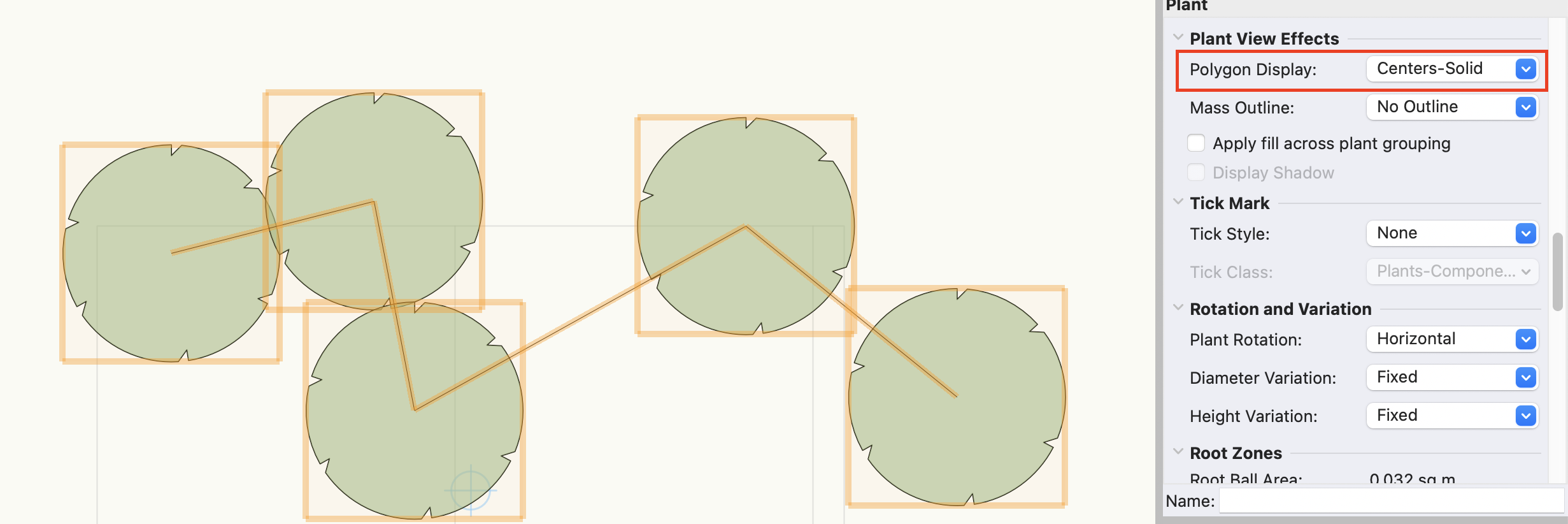
Hi @Daniel OKane, are your plants grouped? If they are, then you should be able to turn this on either in the tool preferences before you place the plant or in the Object Info Palette when the plants are placed. The plants can't be placed as individual plants.
If the plants are individual plants you're trying to combine into a group, first select the plants and right-click. Select 'Change Plant Grouping'. This will create a plant object with several plants in it and you can then add the polygon.

-
Or, as Tom said, use the Migration Manager
-
-
 3
3
-
-
@TeeMuki, I've looked at the file you sent over and have no issues with it. That's why I would like to see how it runs on your machine.
The plant objects are Plugin objects with a symbol inside - this symbol makes it possible to have loads of trees of the same style without slowing down the file. Instead of creating individual geometry for each instance, it uses the power of symbols.
I also looked at your origins and your project is nicely placed, close to the internal origin.
I know there are sometimes issues with plants falling down from the site model if you turn off the site model layer, and the engineers are working on this - however, this shouldn't make the file run slow. If this happens, the workaround is to select all the trees and nudge them sideways, and they should be back up on the site model again. Remember, don't put a specified z-value for plants - they automatically adjust to the site model.
Regarding georeferencing, no connection should affect the performance between the trees and the georeferencing itself - below is a file with quite a few trees, existing trees and proposed, on a georeferenced site. I have no problems adding, moving or editing the trees.
Regarding the BIM trees - the only thing I can think of is (if you're using the UK BIM trees) to go into the 2D geometry and remove the photorealistic image of the crown and only use the sketch part of it. Perhaps your graphics card is struggling with that.
It would be good to get to the bottom of this issue. I'm happy to meet up on Zoom and look at your file. Let me know.
-
2
-
-
@TeeMuki, yes, of course. You can send it via WeTransfer to my email address, kollikainen@vectorworks.net.
Or, you can share it with me via Vectorworks Cloud or Dropbox.
-
1
-
-
@TeeMuki, this doesn't sound like a normal 'tree' problem - there's nothing inherent in trees that should make them work slower than other geometry. Can you please post a file and we can have a look at what's going on?
-
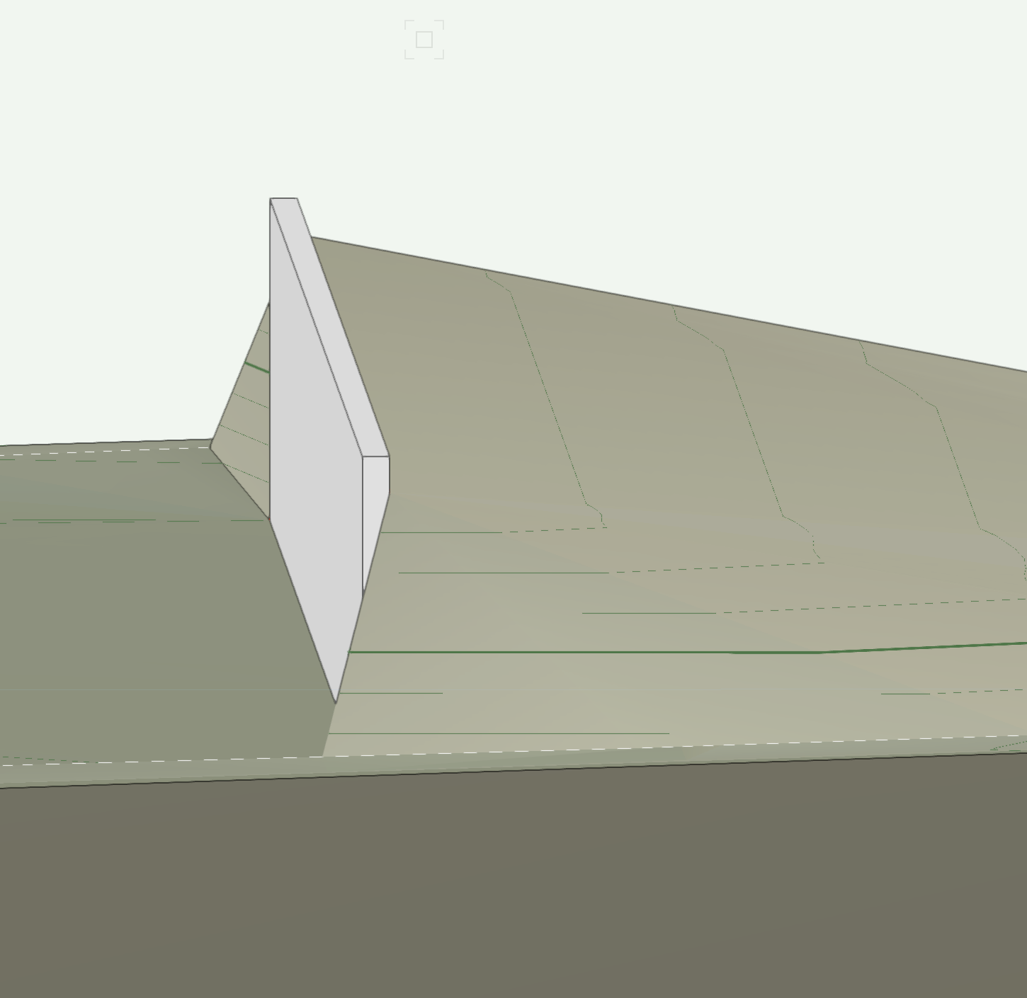
Hi @COBrien, Do you have a grade limit around the wall? The two images below show with and without grade limit.


-
1
-
-
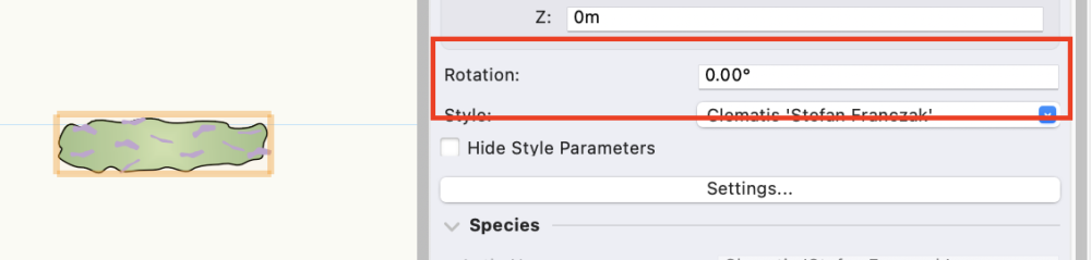
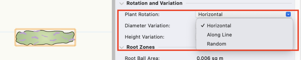
Hi @Hanna N, you can use the Rotation in the Object Info Palette to rotate any selected plants (or any objects), or you can use the Plant Rotation if you want to rotate a line of vines (for example) to follow the line you've drawn.
If the vines are in a plant group, you must change the plant grouping first (right-click and select 'change plant grouping) - otherwise, they'll all react to the rotation as a group.
-
2
-
-
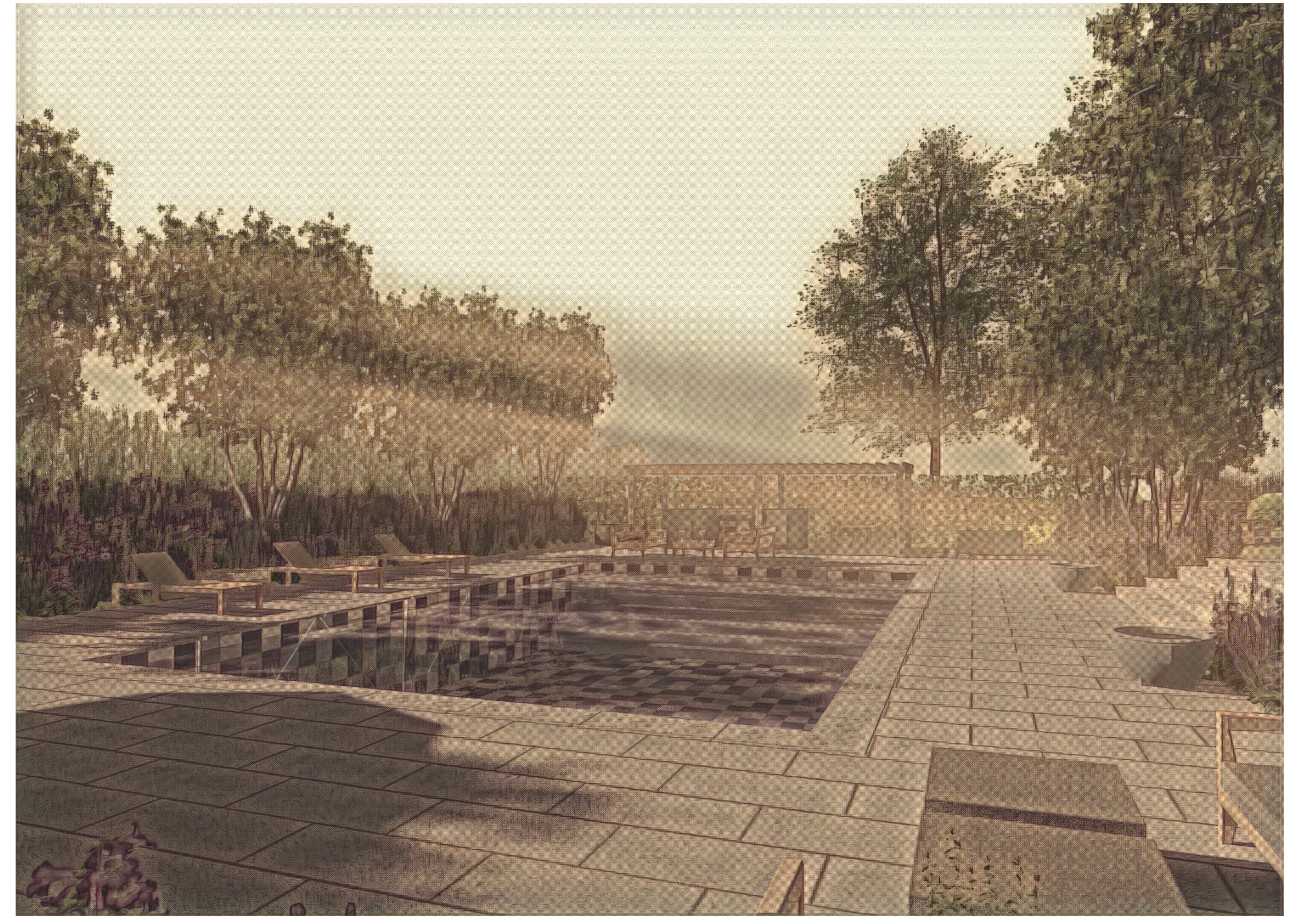
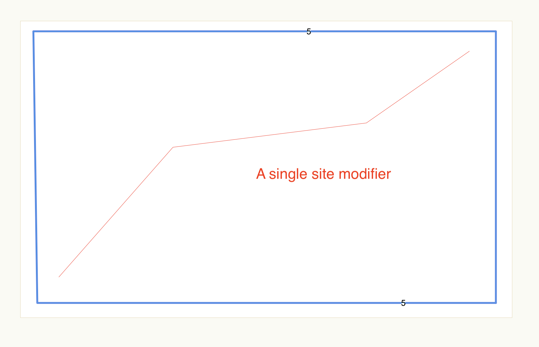
@vassen, if I understand you correctly - you would like a hardscape that mimics the existing site model surface? In that case, use the draped hardscape mode. Remember, you need a grade limit around your site where you place most site modifiers.
I can also see that you're looking at the Existing site model instead of the proposed - change that in the Object Info Palette to see the effect of your hardscape. I've attached a file where I've added the hardscape, as well as separated the layers and change the setup of the site model to listen to only specific layers - this is a good idea as it means you can work things out on layers that don't affect the site model.
-
2
-
 1
1
-
-
On 8/25/2023 at 4:09 PM, bc said:
I hope one is able to adjust the spacing of the main posts in the instances where some are very close together or otherwise, wouldn’t be constructed that way.
@bc, absolutely, you can adjust the spacing of posts so they fit your site and avoid uncomfortable snippets of fence at the ends. However, if you're working with pre-constructed panels, you'll have different alternatives than building a fence with pickets, for example.
The fence is a complex tool, and there are many settings for different scenarios. I would suggest keeping your eyes open for a Coffee Break session soon after the release that takes you through all the intricacies of placing and editing fences and succeeding in making your own styles.
-
4
-
-
- Popular Post
- Popular Post
On 8/25/2023 at 11:34 AM, _James said:Will obviously see when it's released but I don't see why it can't be the same tool with different symbols for railings and fences. In essence they are the same thing, just with different detail.
@_James, we have separated the fence from the railing, as the workflow for a fence differs hugely from a railing.
This has previously been the problem with the combined railing and fence into one tool - it hasn't really covered things like stepped or raked fences, how to edit long sections of fence, and all the details you must consider, which are different from the railing. Theoretically, we could combine them into one tool, but it would be far more challenging to work with - now we have two tools supporting the specific requirements of the two objects.
-
5
-
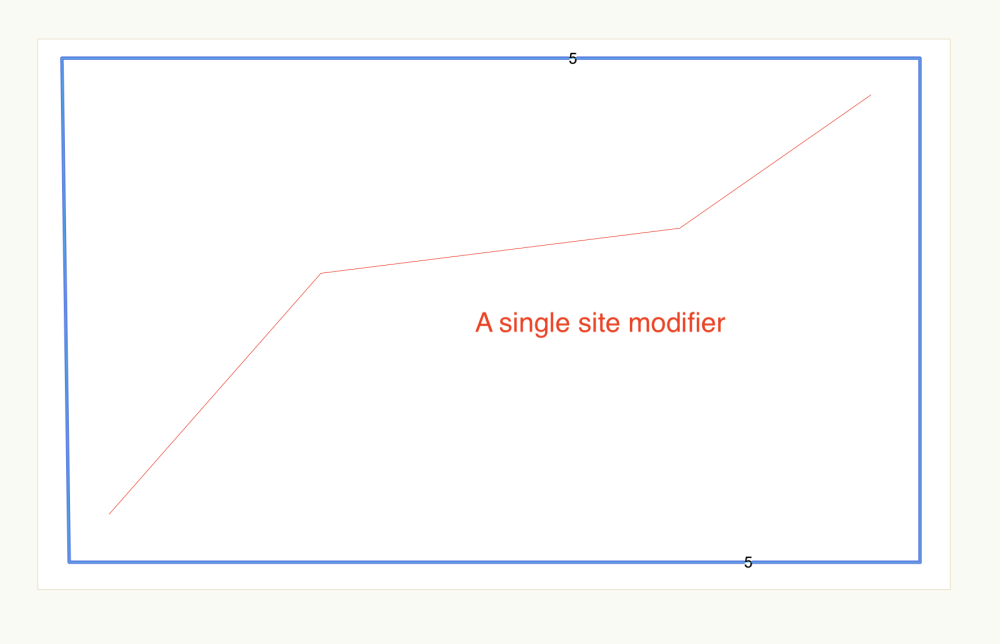
@Phillip Tripp Ok, so I've asked Bobi how the modifier used to work and how it has changed in 2023. This is what he says regarding the contour in snapping mode in 2022:
It must be drawn on the elevation of an already existing contour so it could be expected that (after update) this site model contour will change to follow the Contour modifier. That is why the site modifier tool in Contour mode has a 'Snap to Contour Elevation' mode to help drawing the Contour modifier along/'touching' a site model contour:
However, even though the Contour modifier is correctly drawn along a site model contour, the change in the model contour (to follow the Contour modifier) is not guaranteed both in 2022 and in 2023 and depends a lot on the local TIN there. Because of this, we started thinking about other options, such as the Edit Contour modes (which work much better, and much predictably, but still there are cases they fail) and Site Grading (defined by contours Grade Limits) which is the best option for now.
So, to conclude - the function hasn't changed, and if you have situations when you must have the contour to follow a specific path - use the grade limit in 'Define by contours' setting or use the Edit contours mode.
-
2
-
-
However, the result will also depend on the distance between triangulation points in the site model source data. The other way to do this is to place a grade limit around the area you want to adjust the contour and set it to 'Define by Contours'. This allows you to adjust the contours in that area very precisely.
-
13 hours ago, Phillip Tripp said:
In VW 2022, Contour Site Modifier usually forced the site model to draw the contour where the contour site modifier was drawn.
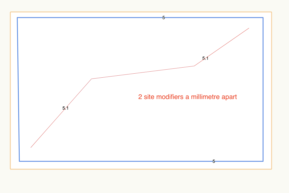
@Phillip Tripp - Please let me know if I'm misunderstanding you, but the contours of the site model are calculated and do not depend on where you place a site modifier. If this was the case, you could only place contour modifiers at the intervals specified in the site model settings. The contour modifier could also have a slope - this is why we changed the name of it - a map contour can only be a single elevation. I believe that if you see a difference in the function, it might be because of the new site model setup and calculations. I'm checking with the engineers and will come back to you on this.
If you want a contour at a very specific position, a trick is to duplicate it and place them just a few millimetre apart - this will change the calculation of where exactly this contour is placed. However, this is only possible to do when the contour has an elevation that coincides with the site model interval setting.
-
@Kevin K, apologies, I missed that. No, it's only available from 2023.
So, for 2022 I would suggest creating the hardscape as a planar pad and adding a slope to it. In the image you posted above, you seem to have an even slope - that is easily done this way.
The aligned hardscape is also useful, and you can add profiles and surface modifiers for slope changes.
-
Hi @Kevin K, I suggest using the hardscape in drape mode if your site is graded and the pathway modifier if you want to change the site model to follow the path. Drape mode will have the volume, and you can have as much as you want of it above grade depending on where you place the datum. It will also conform automatically to the site model surface. Job done.
If you want to adjust elevations along the path, then use the path modifier.
-
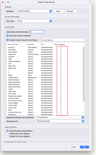
@rbkla, Jeff is absolutely right - the Data tag is the best way to go, especially as the plant tag will be removed in a few years.
However, if you want to do batch editing of your plants, look at this thread on how to use a built-in function - this will allow you to change a setting for all plants in a folder in one go.
-
1
-
-
Hi @Amanda McDermott, I've been off on holiday for a few days so trying to catch up on all messages. Can you please send me the file and I'll have a look.
-
1
-
-
Great, I've attached a recording on how to use this data for the site model. I hope this helps.
Remember, if you plan on making any changes to the site model, you might want to go through some site model sessions on Vectorworks University to avoid getting frustrated. There are a few 'must' rules for site modelling, but it's pretty straightforward if you learn the structure.
-
3
-
-
You can use the 3D data and create a site model from it. Can you post the file so we can see what you have?
-
5 hours ago, TeeMuki said:
the Site Model contours are not always following the Open Edge Line modifier. What could be the reason behind it? Does the Site Model do some toleranced smoothing of some kind when creating the Site Model?
@TeeMuki, Yes, that's correct. I'm unsure of the calculation, but it follows standard rules of where to place the contour. The more drastic the elevation change between each contour, the more aligned with the modifier.
5 hours ago, TeeMuki said:I have all my projects Georeferenced and also the Source Datas are in the right coordinates. I remember though that sometimes i have made a Site Model from the Source Data and the Site Model appears in a different location than the original Source Data. What could cause this? Might it be, that the Design Layer where i create my Site Model hasn't the Georeferenced -selection enabled in the "Edit Design Layer"?
You must be in top plan view when creating the site model from source data; otherwise, it'll scoot away quite drastically. However, the issue with aligning the site model with the internal origin is more significant than that. If you're georeferencing your file, make sure that you also align the user origin with the Norting and Easting (and Lat/Long) before importing anything. Before importing anything, you must ensure the internal origin is aligned with your site. Let me know if you have any further questions on this.
5 hours ago, TeeMuki said:I would love to hear also the alternative ways to reduce the file size.
Ok, so without knowing your source data format, this is how I would do it: I would use all your data and create the site model from it. Then, ungroup the site model in a 3D view and the 3D Style '3D Contours' and delete everything but the contours. You now have your site model data in 3D polygon form. This you can now simplify to the level you find acceptable and then convert this to 3D loci (Landmark > Survey Input > 3D Poly to 3D loci). When this is done, run a validation of the data (Landmark > Create Site Model > Validate 3D Data) to remove any loci duplication and create your site model from the results. If there are some contours you can't live without, then copy them back into the data before creating the model.
This is how I do it if I only have a LIDAR tile (typically one sq km, with 1,000 000 points).
I convert to 3D loci instead of 3D polygons because the site model runs better on loci - the Delone triangulations are simpler.
6 hours ago, TeeMuki said:If the different pieces are in different files, how or what would be the best way to guarantee that the Site Models of each file joins together accurate so that they generate a flawless Site Model when combined
Again, this is quite involved. Let's say you have two pieces of site model, and you're first working on piece A. When done (or at least ready to move to the next part), lay a 3D polygon just inside the site model edge and send it to the surface. This will give you a next-to-perfect 'elevation marker' to copy to part B. When pasted on site model B (on Proposed, not Existing), put it in the Site-DTM-Modifier class. Hence, it becomes a site modifier (the class will be automatically created as soon as you've used any site modifier in the file - you can't create the class yourself).
The grade limits must be right on the cut of both models. You might have to extend the site model slightly on the connecting sides (but crop it so only the correct part is visible) to ensure the grade limit won't 'fall' from the surface.
Let me know if you need more info on this.
-
2
-
1
-
-
2 hours ago, Zsombor said:
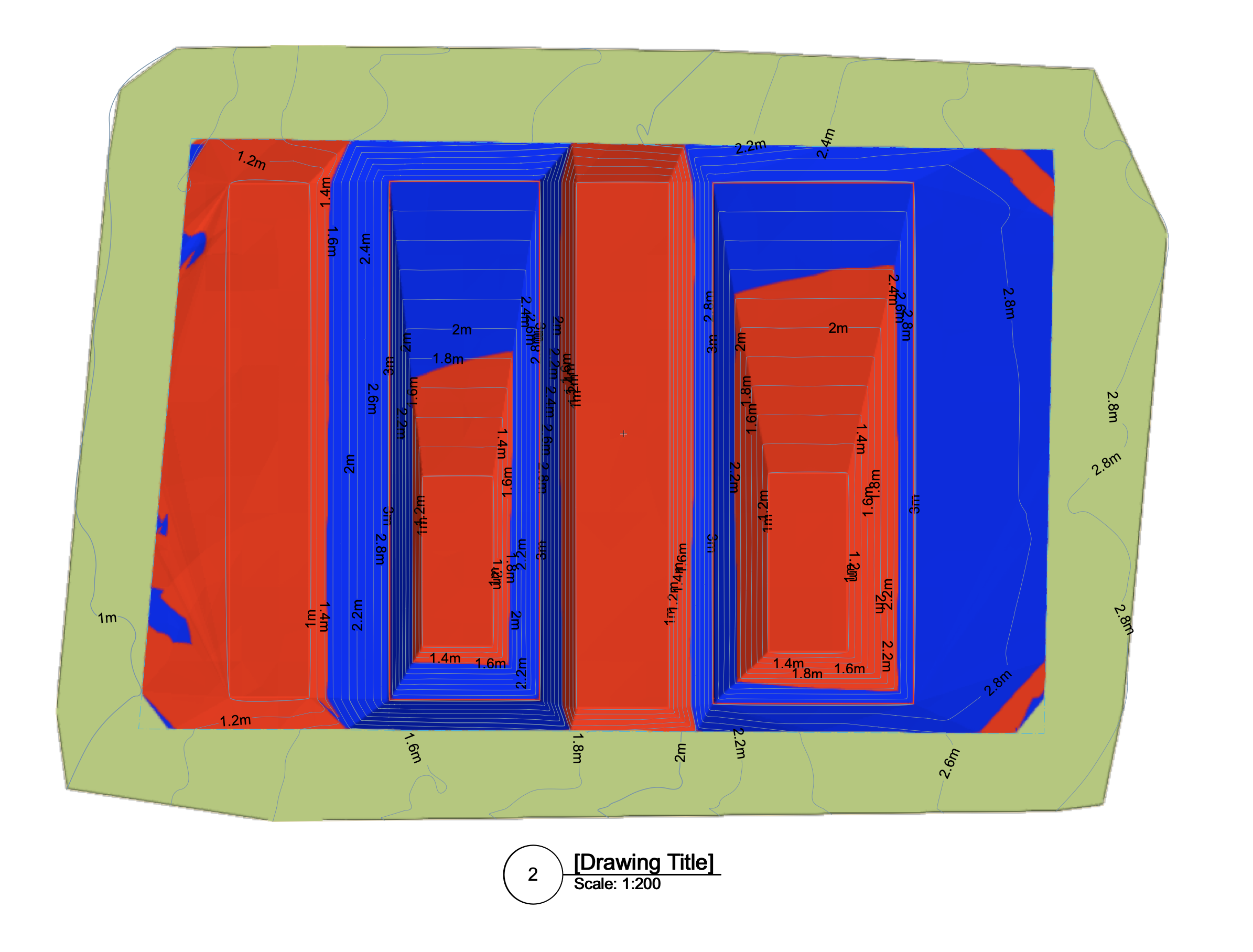
There's the opportunity to see cut and fill volumes with different colors in 3D view. It's really nice, but it would be much better to see it also in 2D top view. There's an option in site model settings/ graphic properties/ site analysis for that but I have no idea how to see the result. Could you please help me solving this issue?
@Zsombor, Jeff is correct - this has been non-functional for a while now. I think they decided not to put effort into it while working on the new site modifiers - this will be rectified and improved. If you really want the C&F image in 2D today, there are a few workarounds (and I'm emphasizing that these are workarounds, temporary solutions). The first one (and the easiest) is to simply set the view to Top instead of Top plan - this way, you can use the 3D display 'Cut and Fill' view, but in '2D'.
If you also want contours, then it becomes a bit more involved. First, create the viewport as above. Then, return to your design layer, keep the view the same, but change to top plan and remove any fill of the site model. Create a new viewport and place it right over the first one. Now you have the contours as well. Also, turn off the 'Display viewport out-of-date borders.
My site model is green in 3D, but if you change it to white, it'll look even more like a standard top plan.
There are a few more things you can do, but try these first and see if this is enough 🙂

-
2
-
-
Hi, here's a link to a recording on how the new site modifiers work from 2023
https://university.vectorworks.net/mod/overview/view.php?id=5243
As a basic:
2 hours ago, TeeMuki said:A have created a site model and now i want to make new contours to it.
How should i go forth?Use site modifiers - pad, aligned, path or open edge. Remember, you're not creating contours but editing the surface with these. The site model itself will make the contours.
If you have precise contours you want to have in the site model, then by all means, use the open edge modifier, but remember that the site model settings will determine at what intervals you will see contours. If there are some contours you want to adjust at the end, then go into the 'Edit proposed Contours', but this is not an efficient workflow to start with.
2 hours ago, TeeMuki said:If i have already made a Site Model and i have to extend the Site Model with new existing contours, how is this the best way to do it?
If i have the Site Models Source Data still at hand, i could ofc just make a new Site Model with the additional contours, but i'm hoping to find the most efficient way to do this...Select 'Recreate from Source Data' from the Object Info Palette. This takes you into the original data from which the site model is created. Here, add any extra data that you have. Make sure not to add to areas where you already have elevations. When this is done, you must go in and edit the crop as well - otherwise, you won't see the extended surface.
2 hours ago, TeeMuki said:Do you have some tips to make the Site Model as light as possible to retain a fluent workflow?
That is a lot of data.
First - make sure the site model is aligned with the internal origin. This is a must. You can't do this by moving the site model - the source data must be in the right place to start with, and the site model must be created there. If it's already made in the wrong place, then use the Origin > Center Drawing on Internal Origin command.
Second - simplify the polylines in the site model data.
Reducing the number of loci before creating the site model would also be good - I don't know in what form you have the data, though, so I can't give specific suggestions.
There are other ways to reduce source data as well - let me know if this is not enough.
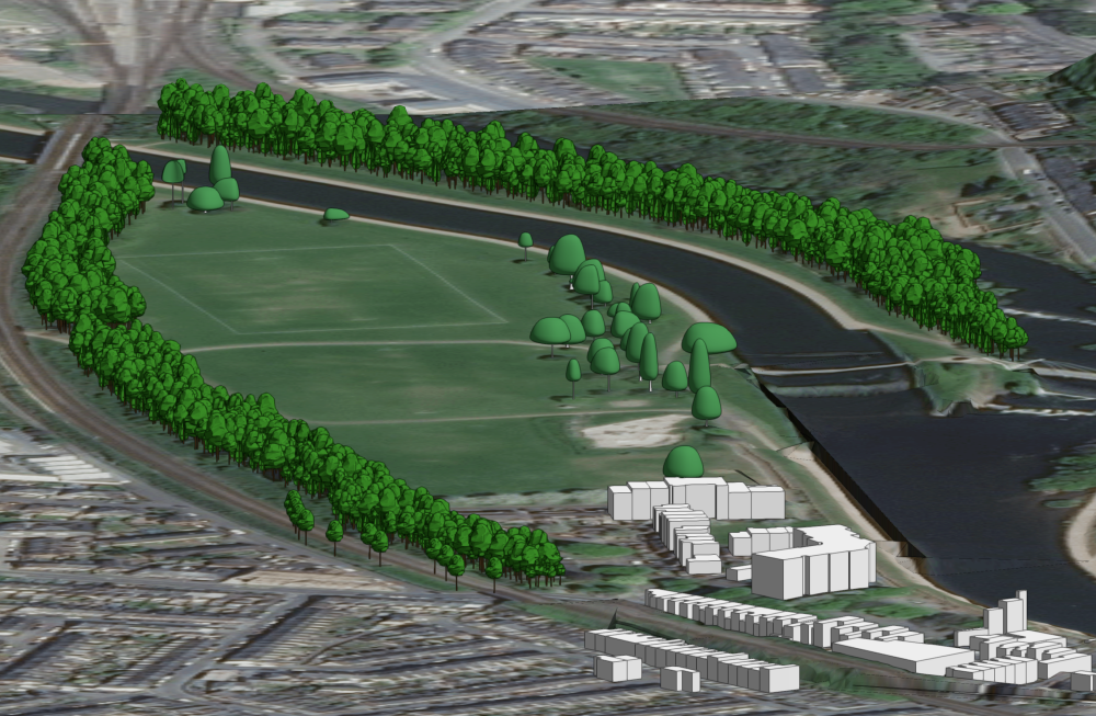
You can't stitch site models together, but you can divide the site into several pieces and work on each in a separate file. Then, in a project file, create Design layer viewports of them, and you'll be able to see the whole site in one go (however, you can't edit in the project file, only view).
You can also work on the parts in separate files and combine them all at the end (copy and paste or import layers with geometry, collect all the source data and create a new site model), but this is a bit involved, and it can be hard to retain the integrity of the data. Any manual copying and moving creates a considerable risk of manipulating something involuntarily.
-
3
-
1
-
-
Hi, my brain must have been on holiday already when responding to this post - the solution is so obvious.
As long as the 'Add to Record' is checked, the data will go into the record attached to the tree object.
You don't have to do anything fancy; it just works.
The only thing is that it's not visible in the Shape pane in the Object Info Palette but in the Data pane.
-
4
-


2024 - Fence Tool Improvements
in News You Need
Posted
@Laura Stone, glad to hear that you like the new fence tool.
To change what end the 'overflow panel' should be at, simply use the reshape tool's Elevation/Edit mode. This allows you to work on a whole section of the fence in one go - this works in both 2D and 3D and can be a very powerful way to get an overview of a fence section. Under the preview, there is a checkbox for flipping the run (see the recording). If it's a raked fence, you can do the same with the post placing.
Remember, if you've placed the fence on uneven ground, you'll then have to use the gravity mode to return it to the site model surface, or to the 3D object you placed it on.
The gate insertion works the same way as for running fences. First, you must have a gate in the style. After that, it's just to insert it with the reshape tool. When you've inserted a gate, the fence section is split, so you can then adjust each side of the gate separately if you want to adjust uneven panels. This will also adjust the fence line to the least number of panels required.