aheininen
-
Posts
71 -
Joined
-
Last visited
Content Type
Profiles
Forums
Events
Articles
Marionette
Store
Everything posted by aheininen
-
Data Tag from record field, shorten record data
aheininen replied to aheininen's topic in General Discussion
Thank you @Nikolay Zhelyazkov you pushed me to right direction. I ended up to use WS_MID and define known characters from start as index and gave enough characters to cover rest of characters in record field. This because either XXXXXX or ZZZZ character are not defined by set amount of characters. Twenty should be enough... End result as Tag Field Definition is #WS_MID('<Record>.'<Field>'; 5; 20)# -
Hi I would like to use data on Data Tag from custom record which is on format YYYY-XXXXXX-ZZZZ. On Data Tag I would like to show only XXXXXX-ZZZZ. String YYYY- to remove is known length, all ways same amount of characters and same delimiter (-) exists. Is this possible somehow?
-
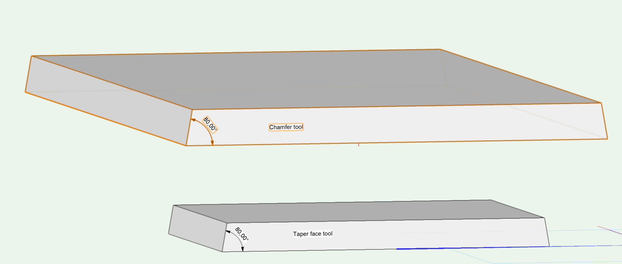
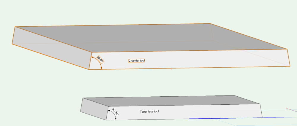
Taper face tool from 3D modeling tool set. Extrude piece. Select Taper face tool, select (bottom) face (with ATL), select end face, set angle with mouse or from keyboard and repeat on other end. Or Draw rectangle. Select Chamfer tool from Basic tool set, set tool mode, from Chamfer too preferences select First Line and Angle, Chamfer rectangle, extrude polygon. You can also use Loft Surface tool but there is even more steps involved.
-
Can you use just regular 3D-model? https://www.mcmaster.com/screws/tapping-wood-and-drywall-screws/tamper-resistant-torx-rounded-head-screws-for-sheet-metal/ When you click product line so that it expands you get drop down where you can choose format to download. IGES or STEP works well. If you make Symbol from model then you can count project supplies on worksheets for example. And you can maybe attach record with information that you need with this screw. Mc Master-Carr has you covered with hardware.
-
Removing connector panels from equipment schedule
aheininen replied to livespace josha's topic in ConnectCAD
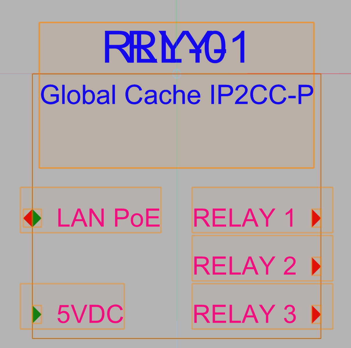
I have used this criteria on worksheet. This assumes that you don't specify Make to your panels.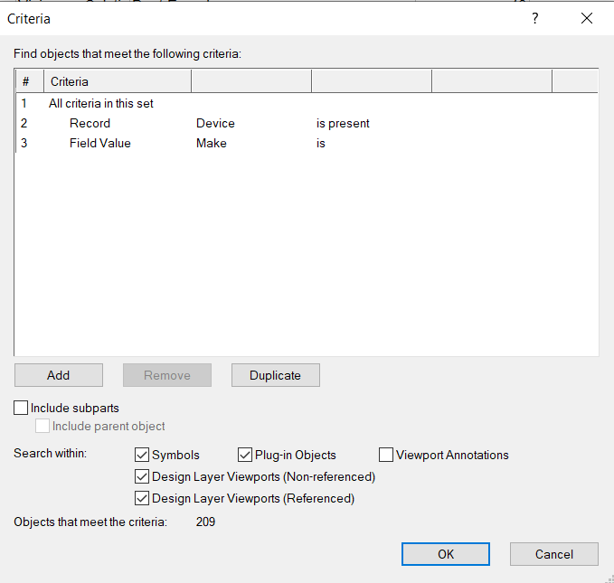
-
That does work like. Thanks again Conrad. -Arto
-
Hi Ben, if you are doing file just that users can use that as a guide then maybe you can Convert to Group command (CTRL+K in Windows) to kind of break Device object first to group then Ungroup (CLRL+U) that group and finally Convert to Group device tag 2D Symbol and Ungroup that. This way you have different parts that forms Devices so you can Data Tag them to show what is parts Class. Finally when all needed is Taged I would Group all parts and Tags together. Obliviously you can't use ungrouped device anymore because it is not real device any more. This is what came to my mind. -Arto
-
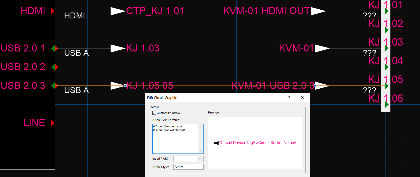
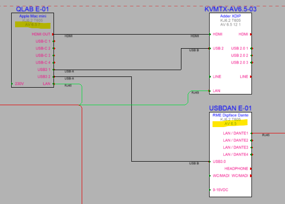
Hi Does Edit Circuit Graphics Arrow Text Formula support use of formulas? Like if I like to show different value if destination is Control panel object or device. This because I would like to hide CTP_ prefix from schematics. It just makes drawing harder to read when you are searching something that is not existing. I have not a single CTP_KJ 1 object on scematics I have KJ 1 objects plenty. You see in example I have connector panel KJ 1 and sockets 01 to 06 but arrow circuit tells me to search object that starts with CTP_ and there is not devices with that name on drawings(Top Circuit). If I use custom arrow with TextFormula #Circuit.Device Tag# #Circuit.Socket Name# then I have duplicate socket info on arrow(Bottom Circuit). Then again if I use only #Circuit.Device Tag# (Center Circuit) I'm missing info of source tag what is valuable piece of information. I would like to use some kind of formula that reads if device name starts with CTP_ then uses Socket Tag information and if it isn't CTP_ uses device name. Or is there better way to not show CTP_ prefixes on arrows?

-
Thanks Dave pointing me to right direction. I have to find time to do a bit of housekeeping then. As a workaround I just modify workspace when no files are open. Seem to work that way just fine. That´s why I wrote this down in here. Should we add this possible workaround to that other thread as well?
-
I have seen this program window flashing with 2021 and 2022 versions with Nvidia RTX2070 on latest drivers Version:472.12 Release Date:2021.9.20. Driver package Studio Drivers. I think time frame is kind of same that you have. Could this be around release date of VW2021 SP4.1? I have not experienced crashes related to this, just flashing usually when program is on background idling. I also have some other display(?) related issues on 2022. If you have open file on workspace and you adjust OIP or Tools panes size or try to change workspace profile I get immediate crash. If there is not any files open then everything is fine, you can adjust panel sizes and change workspace. I have filed a ticket but unfortunately problem is not repeatable on Vectorworks side. And I know this has something to do with my hardware because situation is not repeatable either on my laptop. Just something to inform you all if you have same kind of issue.
-
On Windows, press WIN-key type Vectorworks 2022, choose from right Open file location, right click on Vectorworks 2022 shortcut, choose Properties, click Change Icon, browse to location that includes attached .ico file, select and click OK multiple times. You might get prompt that you need Administrator privileges to make change, just OK that also. Or if you have shortcut on your desktop right click on Vectorworks 2022 shortcut, choose Properties, click Change Icon, browse to location that includes attached .ico file, select and click OK multiple times. You might get prompt that you need Administrator privileges to make change, just OK that also. Later has advance that it changes both icons at the same time. You might need to reattach shortcut on task bar to update change. All credits for graphics goes to @fabrica, I just used converters to .icns to .png. to .ico. logo_2022.ico
-
I think you are on point here. Yes if I put value for row then it is correct. My mistake to miss value for row. Also maybe not desired behavior if you don't put in row values that last seat number takes "wrong" text style. Do you still need test file?
-
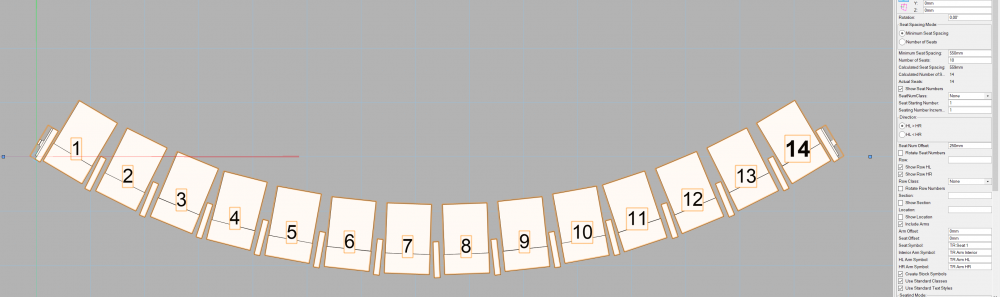
Hi @michaelk great tool. I was testing latest version v2.2 and run into issue with text styles. Last seat on row takes text style from Text Style Row number. Row numbers don't get text style from anywhere. See screenshot. Nr. 14 is bigger than rest seats and Rows are just that handle with no text visible.
-
Yes, I have used Edit Device Array tool you are correct. It has been my go to tool so much that I did not even remembered those to have difference. Thanks for reporting that. Nudge up´n down also works as does your FixCircuitsPath script. I attach it to this conversation also. Script is work of @Nikolay Zhelyazkov all credits to him. -ArtoFixCircuitPathScript.vwx
-
Hi We get this double tag on some of our older devices witch originates from 2018-2020. I recall to have doubling tag problem to be more regular on maybe 2019 version. This is from 2021 version where old device has been inserted. There is additional tag on Sys-Device-Tag class. Easy to remove in edit Device but hard to remember to upload corrected symbol back to workgroup library. -Arto

-
I don't know if this goes to same category but a way to reset connectors on end of cables would be sweet. For example if you have connector panel where you might have made mistake on connector type or input/output and correct the mistake then all cables show old information until you "nudge" cables a bit. This is only way I know to resolve old connector info. If there is other way of doing that please enlighten me. -Arto
-
I have noticed this undo problem to show it self couple of times where devices undo and move to last position but circuits stay put but are shown as connected. Easiest to resolve the issue is to redraw circuit again. Luckily glitches have been on short straight circuits. -Arto
-
Yes, that exactly. Because we have racks with different outside dimensions. 600mm, 800mm and 1000mm most frequently used sizes in 19" opening. Now on drawing we have only 600mm width racks. Tried this but I could not to link text to anything. Link to record says illegal objects selected. OIP is just normal selection from text tool. It has been option previously, at least it has worked. Issue arises when you have example some small devices(3-6pc) from different manufacturers which you know that fit in same real life rack unit and are to be installed to generic rack shelf with out dedicated rack mount. There right most units might not get RackU location to schematics. Half rack might be option in this case. Some times it is not when you have to put two little ones on top of each other. -Arto
-
Hi Nikolay, Opening affects open space in between "rack rails" (19" / 23") and still rack overall width is not 800mm it is 702mm. Yes I have noticed that width affects 3D, I was asking and suggesting if that could affect 2D also. I rarely hand out 3D presentation to installer for example. 3D racks have evolved greatly in couple years but are not yet in level where you can make drawings for installers. Ex. Same devices but information is vastly different. If you have two equipment(Rack Width: non-rack on OIP) on same rack unit, in 3D both are displayed on left side of rack on top of each other. Another thing is that if I have two non-rack equipment on same rack unit so that another is on left side and another on right side the rightmost does not register to rack unit. Registration is only when equipment is on left side of rack middle line. Also if it is computer generated it removes one point of failure to remember to add "strips" on side of some rack, which width is all ready given to program to use as width of rack. You see this width info is there and used in other place but not in another. -Arto
-
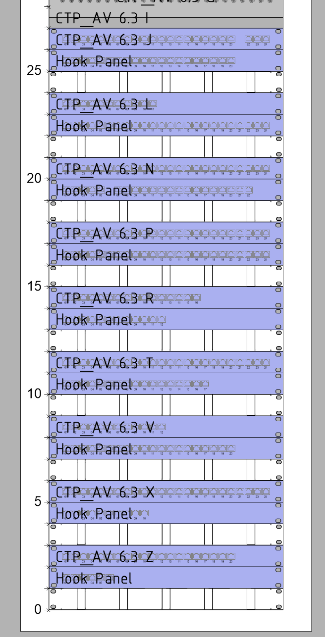
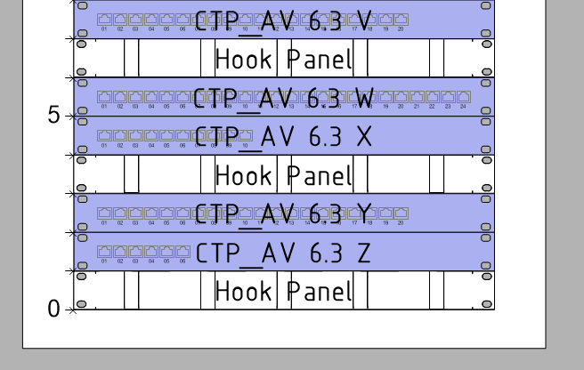
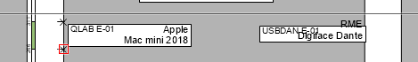
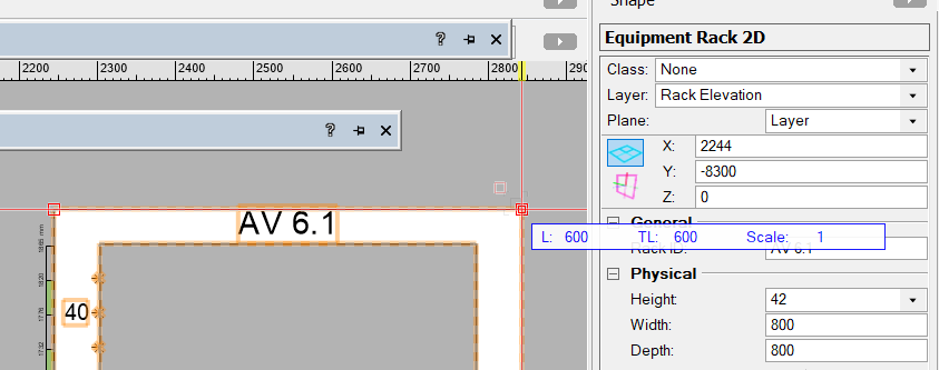
Could / should width of rack on drawing to represent actual width of physical property of that racks PIO.? Now all racks on Rack Elevation are 600mm in width. I would like rack on drawing to represent width from set physical property of said rack. Picture of rack from drawing which has set width of 800mm: It would be helpful to customers, construction workers and installers(even me) to get hang of where different width racks are supposed to be. -Arto
-
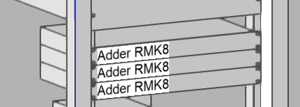
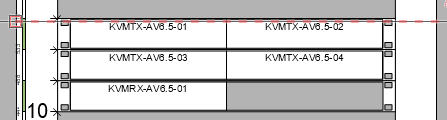
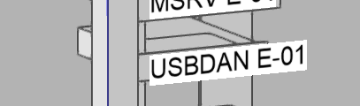
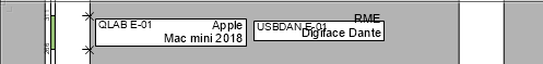
This. And ability to hide CTP_ prefix. Maybe use TAG on this also? Tag could automagically remove prefix and leave only the rest. Also ability to control text placement and style/size more easily. In pictures below we could only show last letter as ID of panel on Rack frame. With freely movable Tag this could be done (like the way we move Cable name tag with handle on Cables). Installer does not need the CTP_ info, this is mainly for VW/CC to identify that Device goes to this defined Equipment and is Custom Panel. Maybe the Panel name/Tag could be on some layer that you can turn of if not needed. We also use custom panels mainly to illustrate rack panels because we are usually responsible only panels on rack side and if we are take care of field panels we try to make at least bigger panels somehow in form of "rack paneling" so it is easy to terminate cables and connectors on field. In this case text on above is only worst solution. Now text offsets by one rack unit and it is difficult to read. VS. text centered: -Arto