Michal Zarzecki
-
Posts
276 -
Joined
-
Last visited
Content Type
Profiles
Forums
Events
Articles
Marionette
Store
Everything posted by Michal Zarzecki
-

Landscape Area that shows 2d plants
Michal Zarzecki replied to bcd's question in Wishlist - Feature and Content Requests
@Katarina Ollikainen, thanks for getting involved in the conversation. I can clearly understand where this might have come from. In our work for example, for large residential or school projects with limited budget and time constraints, we don't have the time for showing each specimen on our plans - we tend to show areas of single or mixed-species. However, I think it would be great if there was a choice - similar to the one we have with the 3D representation. I will watch this space to see where this will take us. Regards, MZ -
Landscape Area that shows 2d plants
Michal Zarzecki replied to bcd's question in Wishlist - Feature and Content Requests
I am all with you guys - that would be really useful to be able to show the specimens within the groups in the Top/ Plan view. @SurroundingsCS , what did you respond to @Tamsin Slatter eventually? Personally, when I propose planting groups, I tend to specify that the contractor plants the same species in groups of 3-7 specimens. I am not a programmer, but if such a behaviour could be at least optional it would be brilliant! What are your thoughts? -
@Tamsin Slatter, I see that this post is from 2012 so just wanted to confirm, if in 2019 this is the same as 'Save Landscape Area...' available from the properties tab? Or there are two different procedures? Many thanks for clarification. BTW, I couldn't gather why I wasn't able to do this with the Pickup and then the Bucket Modes of the Planting Area tool. I suppose they work slightly differently. Glad to have found this post. Regards.
-
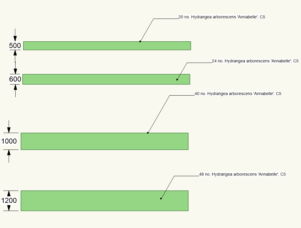
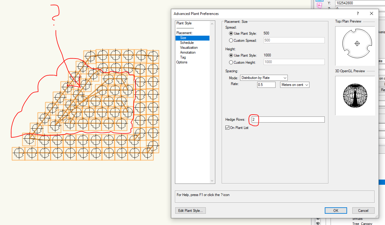
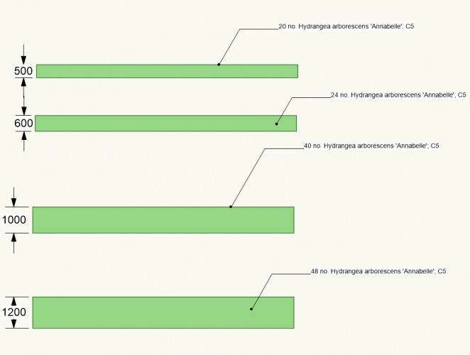
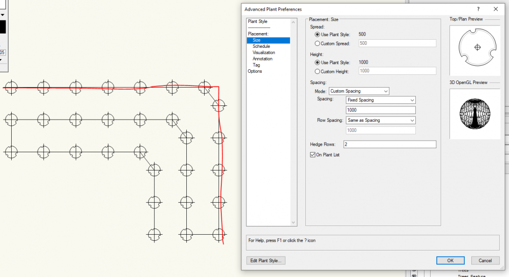
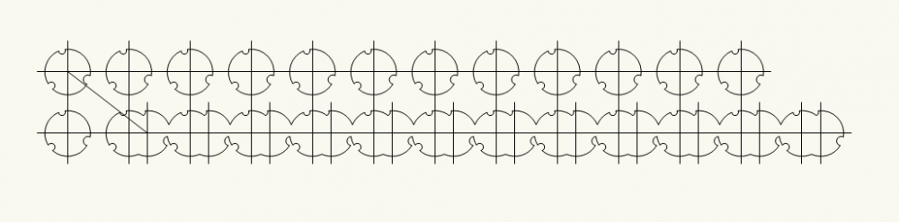
@Katarina Ollikainen , Thank you for posting this workflow. I have started specifying hedges using this method, as couldn't work out the Hedge Mode in the Plant Tool. I was actually quite perplexed to see how VW generates even a single species hedge - as shown in my example above. Perhaps you would be able to clarify that. Perhaps I may simply not understand how to draw using it. Another example below. Why does VW add all that extra plant line? Coming to the Planting Area method. You said Calculate how? See my example below - it's based on the same length of hedge, but slightly different width: In linear features, like hedges, the offset between rows or the width of the proposed hedge doesn't matter in terms of numbers - it's only the length and number of rows that are part of the equation. When one tries to specify a hedge based on the area - they need to be careful what they draw, because the distance is equidistant. Often, one specifies distance between plants to be different than the row offset. In another instance, one may want the same number of plants, but perhaps at different offsets or allow the plants to grow out and form a wider hedge. The width of the polygon drawn starts affecting the calculations. I appreciate the tool and your tutorial though. At the moment, we are where we are, so trying to explain the philosophy behind the purpose of software is in the realm of theory and doesn't get us anywhere. Food for thought for 2021, apparently.

-
@Hans-Olav , thank you for linking to this article. It looks like this can be used instead. I will try to give it a go in some free time. It's a shame a Marionette, created by users, needs to be used to do what the integrated tool should be doing. Many thanks for sharing and regards.
-
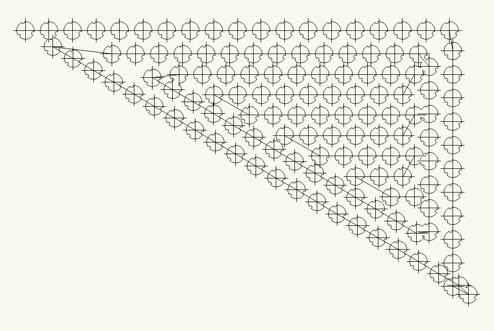
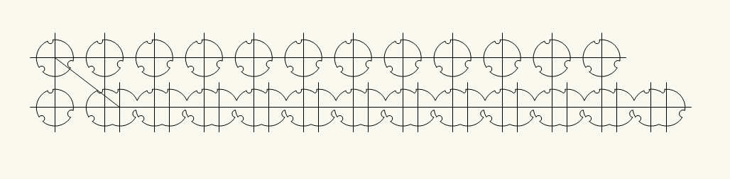
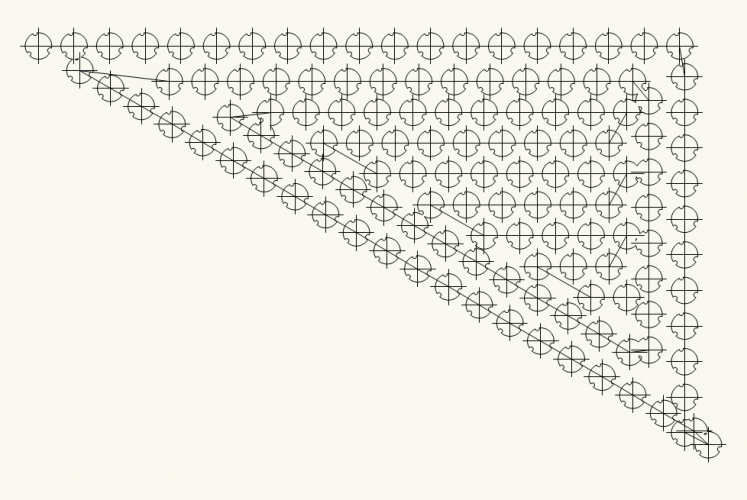
@Tamsin Slatter , Thank you for such a prompt response. I gather that the issue hasn't been resolved yet, which is quite disappointed, taking into account what a number of users mentioned and that such a basic feature like hedge is part of almost every landscape design and needs an efficient tool. I will then use the opportunity to get the Community's help on understanding how the current tool actually works (or doesn't). I am trying to calculate the number of specimens needed for hedges in my project. The scheme has already been designed and now this should simply be a matter of mathematics and scheduling. I have tried all the Plant Tool's modes. The results are far from expected, I'm afraid. On the image below you can see what happens if I try to draw a simple double row hedge at 90 degrees (the red line shows the extent of the polyline drawn). That is a poly-edge mode. I can't understand why the algorithm adds another row. On the following image, you can see teh result when a triangular array mode is employed. Again, the lame polyline. Why would the tool create a polygon, rather than following the polyline and drawing two staggered rows of symbols? Another bizarre example is when I tried to draw just a straight line with the same mode used. The procedure creates a polyline that goes back and forth and populates symbols along the way. I suppose the unruly geometry could be disclosed, but the numbers are nowhere near to be acceptable. It is a great shame that this has not been addressed and landscape professionals left alone [again] with quasi tools which are supposed to facilitate the design and scheduling process. The same operation can be undertaken in under a minute in every basic CAD application which supports any sort of formulas. Basically draw a polyline and get the field calculate the numbers for you, based on the polyline's length. The pretty graphics is a bonus clients don't even appreciate. I really appreciate the help provided every time the VSS team is called or the responses from VW employees here. But please advise, what users can do to get the software they paid good money for help their every day design tasks, rather than spending extra time on tedious workarounds? Regards
-
Hi @Tamsin Slatter, As VW v. 20 is now available and, as far as I noticed, a number of improvements have been introduced (e.g. alignment of Hardscape objects), could you give us an update and confirm if the hedge request has also been adressed? I think this is something that a lot of Landmark users are looking forward to seeing.
-
Guys, has there been a renewed Wish tread on that? I agree that this is far from ideal. I can understand architectural software can lack such tool, but for civils and landscape architects this is a must! Another one is to be able to 'drape' slabs over the site model. Simple planar surfaces don't exist in reality. I do my models with Grade Tool, which is fine, but then in IFC one cannot tell what is what. Perhaps we should team up and lobby for that to be taken on board?
-
@NoemiM , Thank you so much for sharing your workflow with me/ us here. It seems that VW does require a separate style for each plant. Your workflow seems reasonable to me and I have a feeling I would end up with something similar. In my previous practice, where we used another software, I used to create an array of squares with the associated specification of planting areas (i.e. wither individual species or mixes) and tree/shrub symbols which effectively was my swatch pallet. I would then use the 'Copy Specification' command to populate the planting areas and specimen plants in my project. It was like a blitzkrieg. Different soft, different methodologies. I would prefer it to be more flexible, but hey-ho! Working out a good and efficient workflow is essential with these tasks, therefore your option is a much appreciated time-saving tip.
-
Hi guys, It seem that my question is a bit a derivative of what this tread is about. Nevertheless, let me shoot it. I am pretty new to VW. We only recently purchased the 2019 version. What I was trying to do is to define typical styles for, let's say, standard nursery stock trees, multi-stems, herbaceous etc. I thought I would need one style per each, so it presents the label and so on as we are used to it in the office. But, it seems to me that I need to create individual styles to each species and plant characteristics I am proposing in the given project. Is that really so, or I have missed something? In an example, I have a few standards (like 12-14 cm girth) in my project, as well as multi-stem feature trees and a mixed herbaceous layer. I created the styles, but when I apply a style to a tree it can only be of a species that goes with that style. Can I do it generic and then just change/ specify the species? Can you help or point me to the right discussion?
-
Existing trees not sending to site model surface
Michal Zarzecki replied to Helen Palmer's topic in Site Design
I seem to have similar problem. The Existing Tree Objects are not automatically produced on the Model surface. Send to Surface doesn't work either. Plugin Rest - any better. Do I really need to go one by one and identify on what spot level they need to sit? 😩 Productivity 0, I'm afraid. -
Pad with Retaining Edge - The Edge is Zig-zagging
Michal Zarzecki posted a question in Troubleshooting
Hi All, Have you ever come across a behaviour like that? The retaining edge of my pad zig-zags like that and deforms the surface badly. This increases the mesh density. I don't know how to rectify it. I tried the Reshape tool, but these edges don't have vertices at each kink (as you can see). Any thoughts?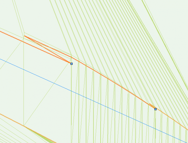
-
Thank you, Tamsin!
-
Referenced DWG viewport classes turn off by themselves
Michal Zarzecki replied to JMR's topic in Architecture
Thanks for your response, @JMR. I must admit I am not sure what you mean by this. Is it a particular facility in VW or it's literally someone else working on the file that I have referenced in? -
Referenced DWG viewport classes turn off by themselves
Michal Zarzecki replied to JMR's topic in Architecture
I may have a similar issue. My DWG drawing Reference disappears after updating. I am using VW 2019. -
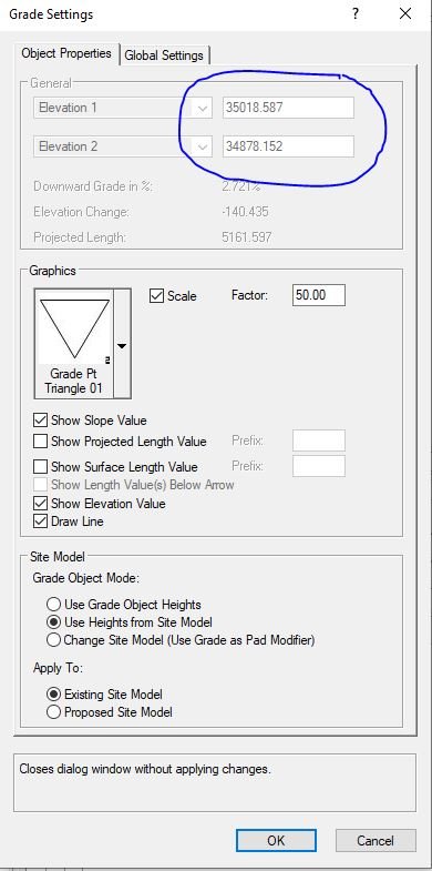
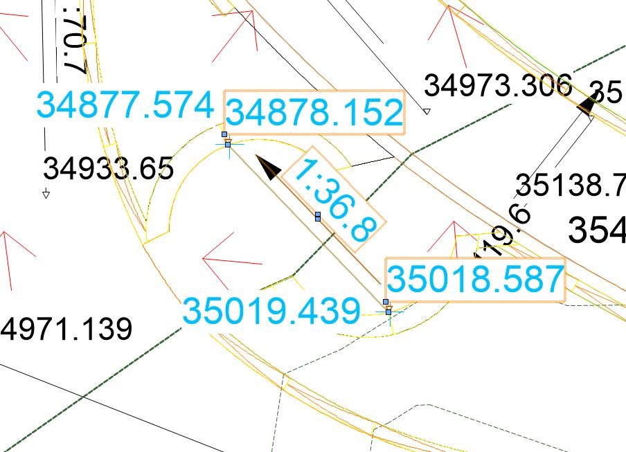
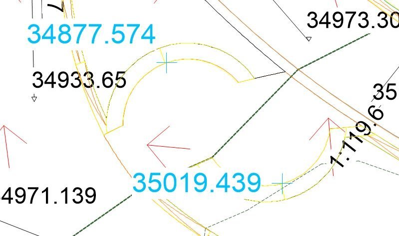
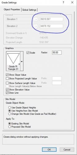
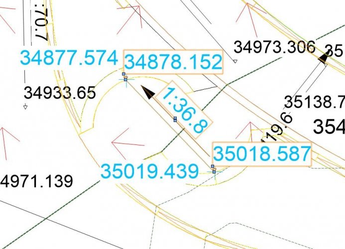
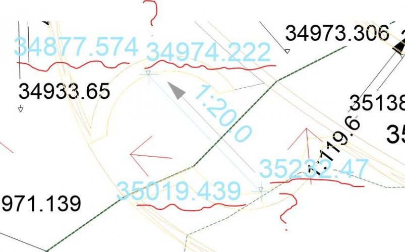
Hi Ben, Yes it is. I haven't used the Sculpting Tool. I actually managed to take some shots of another anomaly we don't understand and which render our reliance on VW just impossible (at least now). Basically what happens is that the values shown by the Grade Object changes after we update the model. When I insert the GO to show the levels from the model, rather than to modify it, it seems fine - the levels at each end roughly correspond to these shown by the Stakes. But once I hit Update on the model - these values change to I don't know what. See some screenshot below. They are from a scrapbook file we are using so sorry if it looks 'busy'. Any ideas on why this is happening? Both the Stakes and the Grade Object use the Existing model values.
-
Hi all, I have searched through the existing topics and haven't found the relevant one to my 'problem'. First, I think I may be a bit confused what is considered 'Existing' and 'Proposed' model. I think that 'Proposed' is everything that VW had to modify on the interface with the existing model created from stakes or loci. So if we set the 2D view to Existing + Proposed, we will see both contours and flow arrows. Please do correct me if I am wrong. Now, I am drawing a Grade which is working in the 'analytical mode' to show me the gradients based on the model elevation(s). The confusion starts when I am to set if it should apply to Existing or Proposed Model. I have this situation when one end of my grade is within the Proposed/ modified area, whilst the other is within the existing. The Grade shows the incorrect elevation at its ends basically. So it either shows the existing values or proposed. Is there something I am missing or a setting to change? I will try to create some shots when I am back to the 'design board'. I hope that in the meantime someone will express their views or share their experience with the matter. Regards
-
The use of stake objects as site modifiers
Michal Zarzecki replied to J. Wallace's topic in General Discussion
Hi J. I seem to have a similar issue. We have had VW for a short while now, but we are using it to create a site model based on our previously designed levels. Also to see if they work with the water flow. It appears that stakes produce localised depressions and peaks, rather than having a wider effect on the site model. In your case, if you are creating a pond, then a series of contours or pads - one per each depth, e.g. every 250 mm. They should modify the site model to faithfully shape the bowl of your pond. I think you should also have a Grade Limit object of the shape of your pond to containg the modifications within it. I am writing that from top of my head, but when having some time I will see if I didn't miss any step. I hope this helps. -
Getting Hard Landscape Levels Right
Michal Zarzecki replied to Michal Zarzecki's question in Wishlist - Feature and Content Requests
@Tony Kostreski Thanks for replying to this one. I have tried various properties of Hardscape objects, including slabs (Datum top and bottom), pad modifiers etc. It seems that something is not working properly. I made a simple trial. I created a simple flat Site Model and created a few Hardscape objects with elevation set to be slightly higher than the model itself. Then I tried different combinations of Slab settings. When Slab Datum was set to bottom (Slab thickness remained positive) nothing changed, i.e. the elevation in properties indicated to be at bottom of slab. Nothing seemed to change when I set Datum to top. OK, the thickness of slab changed automatically to negative value. I considered that bizarre. But, when I changed slab thickness manually to negative value - Eureka! The Hardscape object dropped - the elevation became the top of slab. I just can't understand why it didn't react this way when I set the Datum to top in the first attempt. It must be a bug. Perhaps someone else can review that behaviour? -
Getting Hard Landscape Levels Right
Michal Zarzecki posted a question in Wishlist - Feature and Content Requests
1. Hardscape Object 'Levels' I am not sure how about others, but I feel very confused about elevation property of hard landscape elements (Hardscape objects, Steps etc.) in VW Landmark. I mean, I think I understand the concept - it is a vertical value over the Design Layer. However, the interpretation is very confusing and counterproductive. An example: If I have a Hardscape object set to be 3D slab in my site design with an elevation of say 10,000, it means that the bottom of the slab is at this elevation. Technically, everything is logical and terminology consistent. Now when I assign a slope to my Hardscape, I will get properties to show what is the elevation at the start and at the end of the slab. But how does this information help me understand and design the levels, since I am not interested what the bottom of hard landscape surface is - I am interested in the top surface! If I understand the tool right, I always need to take into account the slab thickness when thinking about the level on top of the Hardscape object's surface. This is an extra maths I need to do which is hardly helping me in my work - it's actually to the contrary. I may have a wrong understanding, but I always thought that computers and software should help us with productivity. So, when working with a digital tool with powerful site modelling features, I would really appreciate it being helpful. I appreciate all the work which has been done to the Hardscape tool, but could at least the Finished Surface Level (or something along these lines) be added to the properties tab? This really needs to be a term used in the industry, not some developer's lingo developed for the sake of the software. 2. Stairs 'Levels' Stairs is yet another helpful tool in creating parametric objects. Again, rather than performing maths here with setting up height, can Finished Surface Levels be added here? When setting up the Stairs, under General Tab, the general geometry parameters include Height, which can be set up by value or layer elevation. Why not by top and bottom lovels? For example: I have to design steps to the existing building, where new doors have been made. I have an FFL given as well as surface level of paving around the building. It would be very helpful if I could start creating stairs in VW by typing in these values. The rest should be calculated by the software itself. Also, an optional tag with Top of Steps and Bottom of Steps would be much appreciated. As in the first part of the question, VW adds to the confusion around spot levels here. Rather than Elevation property, we only have a Z Value, which practically seems to be elevation. What would be more practical for landscape professionals, is the bottom of steps level property, which should tie the stairs with the finished surface level of Hardscape objects. I hope the above description of my issues makes sense. I am really curious if this is only my impression or other users also have hard time with getting these right. Regards, G -
Railing Fence Tool - Corner Posts
Michal Zarzecki replied to ericjhberg's question in Wishlist - Feature and Content Requests
I have just used the tool for the first time and feel really disappointed - again 😥. I can't understand that there had to be maths behind rotating them posts, but apparently they [VW] can't update the tool to give the user the flexibility and choice. Similarly, I found the post positioning tool extremely unintuitive. Seems that I will have to model that from scratch. I second that. Tried to create a bin store with metal frame inside the enclosure. I couldn't find a way to offset the timber slats from the frame. Now I can understand why - there is no such option. It seems that there should be separate tabs for panelling and frame. Then once could specify the number etc. of horizontal or otherwise frame bars and separately what is attached to them. I haven't even got there yet, but I wonder what I will come across when trying to specify the gates 😱 -
I second the wish. It was quite surprising to me that there is not proper hedge tool in VW Landmark. I would envisage such tool to create a hedgerow with number of rows set by the user. One should be able to specify planting in staggered arrangement as well, as this is the typical planting method. Ideally one could specify the profile of a hedge for better representation of the design intent, such as tapering or box shape. I wonder if such hedge could also work similarly to the Wall tool, i.e. where hight could be modified along the hedge. Native, mixed species hedgerows are very often specified in the countryside, so this should be an obvious option for such Hedge Tool. Sometimes, this is actually explicitly conditioned by local authorities. There should be no need for a workaround to achieve such a basic task undertaken by landscape professionals. I hope that will be picked up by the developers.
-
@bgoff , that sounds promising. I need to try out how that works.
-
Hi All. Interesting ideas and solution above. Will definitely need to try these out. When using the Hardscape tool for the first time I felt that the tool needs a bit of love. I think that it's not only about the visual aspect, but also the specification. I was quite surprised that the information in the tag was so limited. It would be amazing, if one could not only define the visual side of things but also the technical one. Imagine there are fields where you detail the proposed manufacturer, jont width, perhaps mortar etc and this is then automatically included in the tag. The latter could be styled, i.e. one could choose what item of the spec to include. Another thing is the edging discussed in this thread. Perhaps one could define the profile of edging, similarly to the possibilities offered by the Railing tool. So, imagine you have a default choice of BS kerbs, block eding, setts and you can add your own. And the concrete bedding and haunching as well 🤩 . What do you think about it?
-
In the practice I work in we have only recently started using VW Landmark as the first step towards BIM. Having trialled a number of landscape packages I must admit I am quite disappointed about the translation of the physical process of thinking of and designing site levels and drainage into the digital processes within software packages. The way we usually do it is by working out the spot levels and falls, based on the existing levels, FFL, drainage strategy. Basically, we calculate everything and try to make sure it's compliant and would drain efficiently. I was hoping that software would do part of it for me and I could annotate the resulting levels on a plan. In the process, I was shocked to learn that stakes do not read elevation from hardscape objects/ surfaces, walls etc. These are basics! I was modelling external steps recently and had a really hard time understanding what level the landings were at etc. I then tried to find a tool to actually allow me to read the spot levels from the resulting design. Another struggle. I needed to read the elevations from the end of slopes to hardscape slabs, figure out what levels that actually was and use a stake as a marker. Perhaps someone here can advise on the better way? I really wish that the developers take these requests seriously into consideration, since at the moment we need to do workarounds rather than being supported by the software.
- 21 replies
-
- 6
-

-
- site model
- grading
- (and 2 more)