jcogdell
-
Posts
970 -
Joined
-
Last visited
Content Type
Profiles
Forums
Events
Articles
Marionette
Store
Everything posted by jcogdell
-
load that is not attached does not issue an error message
jcogdell replied to Leppi's topic in Braceworks
Hi Sebastian can you pm me the file so I can have a look? Gruße Jesse -
2020 - all lights offest upon opening a 2019 file
jcogdell replied to ajemutt's topic in Entertainment
Hi AJ Your best bet is to reach out to tech support, they will be more than happy to help fix what ever is causing the problem with your file -
no problem, I will pass on your suggestion to the developer.
-
Multicable labels, and multicable circuiting tool.
jcogdell replied to Ryan Lilly's topic in Entertainment
I will add these to the enhancement request -
Not for your fixtures but to identify the truss system and sub lines that you would have in the box truss scenario you descibed. Yes you are correct the ability to auto populate the position field of fixtures when you insert them or move them between hanging positions is currently the main benefit of creating them. Our objective is to eliminate the step of having to create a hanging position to have this functionality with the fixtures and other hung objects. When the hanging position was first added to Spotlight, trusses and pipes didn't detect and associate fixtures as being attached unless you used the command. Now because of the requirements of Braceworks this automatically happens in the background, what is currently missing is the auto population of the position field with the truss system name.
-
@Peter Neufeld Auto populating the position field of the lighting device is currently the main reason to still use hanging positions. At the moment Trusses and pipes already automatically associate lighting instruments and other load objects with the truss system and truss line they are hung from, this is necessary for Braceworks to be able to correctly calculate the system. We are looking at leveraging this to auto populate the position field in the lighting instrument, I currently do not have any info about when this will be implemented. Regarding the Truss object ID field, this is is the id of that section of truss (if you give it one), the 'Truss system' field further down OIP is the combined name of the truss system and truss line. There are 2 fields that are used to create this, 'Truss System' and 'Truss Line' which can be accessed in worksheets. @Benedick_Miller Personally I would use the truss line identifier part of the truss system for this, and use a custom data tag to label it
-
Multicable labels, and multicable circuiting tool.
jcogdell replied to Ryan Lilly's topic in Entertainment
After looking into this further you are correct, currently you can only do this with records and not the lighting device. I will make an enhancement request to have this changed -
If you are referring to using the assign circuit command to connect a plug box to a rigging hoist, you need to set the 'Circuit Assign preferences' dialogue to use 'Hoist' and then set the 'Place cable id Field' and 'Assign data to multi break out field' settings appropriately. The next and probably the biggest, issue is that the 'soca 7' and 'Hubbel for power and Data' connector/plug box types do not exist in the multi cable tool but do in the hoist object. You can edit them into the multi cable tool using the plug in editor, but due to the nature of this plug in you would need to re-customize them every-time a service pack update is released, as service pack updates reset all the standard plug-ins back to default during the update process. My college Brian, made a really good guide for how to do this in the linked thread below
-
Multicable labels, and multicable circuiting tool.
jcogdell replied to Ryan Lilly's topic in Entertainment
for questions 1 and 2, go to the spotlight menu>cables>assign circuit preferences. the settings are there for your third, if you go the multicable jumper preferences you can tell the command to not draw the cables, however this will mean they are not created, so they won't be included in any cable worksheets. Putting them in a separate class or layer to control the visibility is the best solution if you want them included in the cable list -
To be clear we have no plans of removing the function at this point, it does however cause issues in several areas you can't easily add more trusses to the position with editing it or running an extra command if the hanging position is created as a symbol it can cause problems when using the new MVR file format It makes it difficult to display the trim heights for trusses and pipes that are inside as the hanging position 'Z' coordinate is not easily accessible in worksheets or with data tags (to the best of my knowledge) and a lot of the functions that are part of the hanging position can be done just as easily using other tools like spotlight numbering or the instrument summary tool I will definitely check your worksheet, I am very interested in how you got that to work. One thing I love about this job is there is always something new to learn to address your points regarding hanging positions first you can rename a truss system to whatever you like using the rename system name command in the OIP, this will automatically rename all the elements of the system. By default the system name will reflect the order the truss system was inserted into your design. if the truss system has more than one line because it has corners in the system the line name will be displayed after the '-' in the system name field in the OIP for example T1-2 would be truss system 1 line 2. Using the 'Truss' record when setting up your worksheet you can access 'system name' and 'line name' in the criteria, combined with the model name and count function you can create truss counts broken down by the system. For labeling the truss system, I recommend using data tags, these can display a lot more information than just the name of the position. I tend use a tag with truss system & sub line name and the trim height Your point about the hanging position help documentation and best practice is well taken and we do need to update this.
-
Currently if you create a hanging position from trusses it is no longer possible to reference them in a worksheet. The hanging position is a very old part of Spotlight and many of the original reasons for using it no longer exist, such as associating lighting fixtures and other plug in objects with trusses and pipes (this is know automatic and controlled using the auto positioning settings in the Spotlight preferences) The 2 main reasons for using it are paperwork, specifically the preformated reports created by the generate paperwork command, which a lot of people still use and the ability to create hanging positions from any piece of geometry, such as a simple 2D rectangle To be able to count the trusses in a worksheet you will need to run the 'un-group' command 2 times on the hanging position to revert the trusses back to truss objects. This will break the hanging position, the first time you run the un-group command you will get a warning dialogue that you are about to un-group a high level object, you can ignore this as it is what you are wanting to achieve.
-
There is a tutorial video on the new Vectorworks University, that walks you through the process of adding speakers symbols to the speaker array tool https://university.vectorworks.net/mod/scorm/player.php?a=5¤torg=articulate_rise&scoid=10
-
Just to be clear this bug only seems to affect the truss objects produced by the old straight truss tool and not the newer insert truss tool which is manufacturer symbol based.
-
Thanks Pat I didn't know this existed. Hopefully they will update it for 2020
-
Vectorworks will not do this sort of animation. We can render walk-through videos of of you design with static figures but this is about as close as you can get to what you want. Potentially, if you have access to Vision and understand how to program lighting consoles you could use the DMX transform feature to move the figure around in Vision, but it would not be animated as such, just moving it in 3D space within a predefined movement range.
-
Problem exporting 3DS file and "Normals"
jcogdell replied to awlightingdesigns's topic in Entertainment
I'm afraid @rDesign is correct that we currently do not export the PIO geometry normals correctly and as this is not my area of specialty I am not sure how to correct them. In case it helps I have attached a en example of a custom stage deck symbol I created myself with high quality textures, I know will works correctly in Vision when sent over as an MVR but I am not sure how it will look in MA 3D. It was created as 2 simple extrudes, one for the legs and 1 for deck itself. Let me know if it solves your issue, The only other thing I can suggest at this point is to get in contact with tech support and see if they can suggest a solution @rDesign I got some more info from my colleges about the texture normals and our progress to date, we currently are only exporting texture normals as grey scale height maps and so far this is specifically for the new MVR file format. However I know that the team is also working on creating plugins for Twin motion and Enscape simple stage deck example.vwx -
Another option is to use the new 'Modify truss object color' setting in the Spotlight preferences- loads and rigging pane. This only applies to the 2D geometry of a truss object, but allows you to use the attribute palette to control the pen and fill color of the truss directly, either at insertion or when selected later. This can also be combined with the new automatic truss object classing. Making it very easy to to set up a template file with separate classes for each type or length of truss (to match your specific workflow or favored set up) and give each a class pen and fill color which will be automatically used at insertion, or when the truss is assigned to the class. So for example you have one for silver truss and one for black truss, a class for each type of truss or a class for each length if you are using only one type of truss in your drawing. When this is combined with live data visualization (for 3D views) it potentially eliminates the need to create custom colored truss symbols, unless you need them for rendering purposes or a specific work flow.
-
Problem exporting 3DS file and "Normals"
jcogdell replied to awlightingdesigns's topic in Entertainment
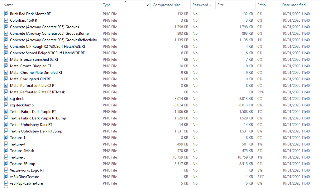
I know this has been a long term bug/issue. As of 2020 sp2 Vectorworks will correctly export this data correctly as long as the texture has been correctly prepared. (This refers to texture normals and not geometry normals) The first step in the process of addressing the issues with texture and geometry exports, has been to get VW to export the texture normal data correctly ,using the image option in the edit textures dialogue. In practice this means currently that all the 'shaders' have to be set to image (or none) in the edit texture dialogue. All the other options use procedural 'shaders' designed for renderworks and will not export correctly for other applications. As far as I understand (and I may well be wrong as i am a lighting system tech and technical planner by background not a 3D designer or artist) we still have to use an external app like crazy bump to create the normal map for Vectoworks to use with the bump shader, but once this has been done the normals can be used in Renderworks and will be correctly exported to other applications. I know this process works correctly with the new MVR file format but I do not have any experience with obj, 3ds or the other file types and will have to speak with the rendering development team to find out the current state of play regarding these file types. If you have Spotlight or Designer you can check the MVR export by changing the .mvr file extension to .zip and looking in the resulting uncompressed zip folder. If the textures are correctly formatted they should export in 2 to 4 .png files in the folder, the first will be color shader image and the other parts have had in this case bump, reflectivity or transparency added to the name. Below is an example, from a recent project file This can also be checked inside of Vision (if you have access to it) as Vision has the option to render normals and specular maps to help you check imported files. Due to Vision's development history it works in line with other rendering applications. As I said earlier this is just the first step and the dev team is working hard to fix the remaining issues.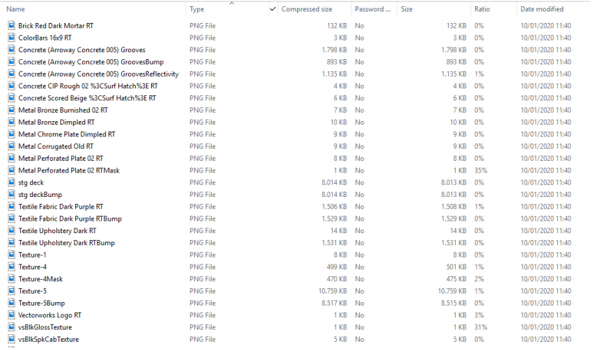
-
If you want tech support to check the file, get in contact and they will look it over! Any files shared with tech support will be kept confidential and only used for texting to locate your problem.
-
Problem exporting 3DS file and "Normals"
jcogdell replied to awlightingdesigns's topic in Entertainment
for the bump shader image try using the free app crazy bump to edit it and then reload into VW. Crazy bump correctly creates normal maps and was used to create the normal in the example above. Other wise I am out of idea's. I will contact a college in the US and see if they know how to fix this -
There are a set of text files that ConnectCAD uses a set of text files to store this type of info. To add a new connector or signal type you open the appropriate file and add the new types, make sure you follow the format that is used in the text file! The files are located in the Vectoworks application folder, Vectorworks 2020 > Plug-Ins > connectCAD-Data The files are clearly labeled and can be edited with any text editor. It is a good idea to make a back up copy of the files before you make any changes Also the custom connectors and signal types will only be available in your copy of VW. If you want to have them available in project sharing environment or for colleges to be able to use the new connector and signal types, they will need to do the same customization in their ConnectCAD data files.
-
Problem exporting 3DS file and "Normals"
jcogdell replied to awlightingdesigns's topic in Entertainment
Try inverting the bump shader image of the texture, edit the texture, and select the edit option for the bump shader. in the dialogue there is a invert button. -
This should happen automatically when an older file is opened in 2020, as part of the conversion process If for whatever reason it has not happened, there are several ways to do it For lighting instruments you can use the find and modify or the replace instrument commands in the spotlight menu. Or you can use the replace lighting device command found in the OIP shape pane for the Selected instruments For Trusses the quickest way to fix them is to select and insert a sections of the used type (doesn't matter about the length) from the default library and as you insert it into your file it will trigger the resource conflict dialogue. Choose replace and it will update the exiting truss symbols of that type. You can also use the replace truss type command from the spotlight rigging menu or if the its a custom truss symbol that is not being correctly detected as a truss symbol the convert to truss and the convert to truss symbol commands in the Braceworks menu Another option that will work with any symbol type in our content library is to open te resource manager, find the desired symbol in either the default or service select section, select and right click on it. in the right click menu choose import. This will again open the resource conflict dialogue, choose replace and the symbol definition in your file will be replaced with default symbol definition from the VW content library.
-
Frequent GPU crashes on 5K iMac (late 2014) and VW 2018
jcogdell replied to acttheatre's topic in General Discussion
What type of GPU is it and how old are the drivers for the GPU? Also how big are the VWX files? -
@michaelk is correct. it is no longer necessary to delete the 2D geometry, as long as you are using the 2020 version of the instrument. If you have to work on a file created in 2019 or older make sure to update the symbol definition in the file otherwise the new rotation fields will not be accessible.