jcogdell
-
Posts
979 -
Joined
-
Last visited
Content Type
Profiles
Forums
Events
Articles
Marionette
Store
Everything posted by jcogdell
-
The .lit after the mode name denotes that it is a Vision fixture (each mode is a separate fixture in Vision), this is a known issue and is being worked on.
-
As far as I can tell the fixtures are working correctly with DMX and I have control of the RGB channels. I think the problem you are encountering is that to be able to use the RGB controls you have to make sure the 'cross fade to color' channel is set to 100%.
-
What console are you using? and which DMX protocol (Artnet, sACN, ...) Does the the DMX viewer show that Vision is receiving DMX on the correct channels? Are you using the default Vision .lit fixture files or a GDTF? Which specific mode of the sky panel s360 are you using? (each mode is a separate fixture if you are using the Vision .lit files)
-
Creating Custom Lighting Fixtures
jcogdell replied to westonteatlanta's topic in Vision and Previsualization
Currently there is no way that a user can create a standard Vision fixture (a .lit file), however there are several potential work arounds The first would be to leverage the Vision RGB emissive textures. You would need to correctly set up the geometry of your set pieces, so that each area that you want to have LED tape in, is a separate piece of geometry and you would have to use MVR file type to get the object into Vision. The main drawback of this approach is that you can only set up the emissive texture in Vision and not in Spotlight. Another possibility would be to try using the GDTF fixture builder to create custom lighting device based on your set piece design or for LED tape. The GDTF builder is available on the GDTF share website, linked below https://gdtf-share.com/ -
Vision transparent MVR material
jcogdell replied to mhersland's topic in Vision and Previsualization
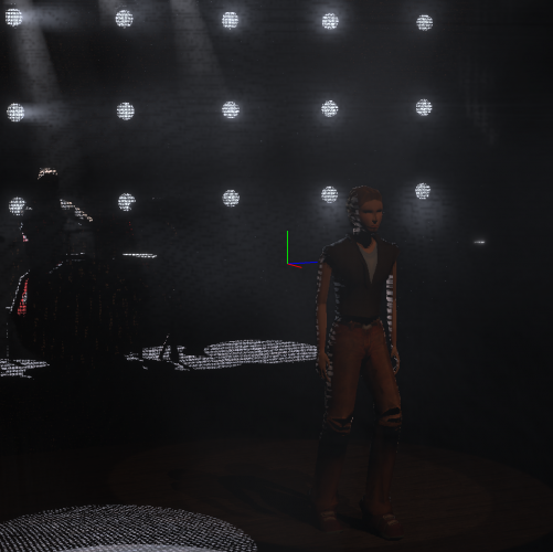
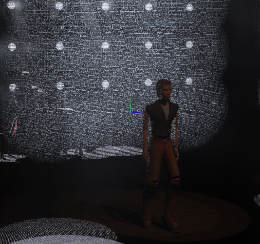
Is the mesh image you have prepared for the transparency shader a black and white mesh? from your screen shot it looks solid gray, which will work in VW but not in Vision below is an example of a kabuki gauze texture and how it looks in Vision Gauze transparency shader image Vision screenshot without the texture normals inverted With the texture normals inverted (to invert right click on the screen in the scene graph)
-
Vision transparent MVR material
jcogdell replied to mhersland's topic in Vision and Previsualization
Correct you will need to prepare the images for the different shaders outside of VW in most cases. Gimp (GNU image manipulation program) is a really good free free app for the basic image editing and NormalMap-online is the best free way I've found for creating bump and reflection maps. -
Our ladder trusses each have 2 sets of symbols to address this issue, one 'flat' and one 'upright'. Depending on the truss library you may need to activate the straight truss tool and search using the toolbar drop-down rather than just selecting in the resource manager
-
Vision transparent MVR material
jcogdell replied to mhersland's topic in Vision and Previsualization
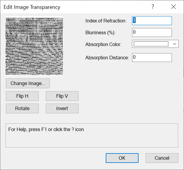
Your problem is the combination of 2 issues, The first is that Vision can't render partially transparent textures. It can do alpha map textures which will control where a object lets light through but either all the light goes through at a given point or none. The second is that you have have used one of the procedural shaders in preparing your texture in Spotlight, if you use anything other than image (or colour for the colour shader) the texture will not export all of its data correctly for Vision (or anything else that can read an MVR). To get the effect you are looking for you will need to use an alpha map texture of a fine mesh and probably invert the 'normals' (right click on the object in the scene graph) so that the lights interact with it correctly. The VW university link below is to our new workflow doc that explains how to prepare textures for export to Vision when using MVR https://university.vectorworks.net/mod/scorm/player.php?a=373¤torg=articulate_rise&scoid=746 and this is a forum thread about preparing textures for use in Vision -
Because the file was created in 2019 the fields will display in 2020 (or if you are using 2019 and older symbol definitions in a new 2020 file), we couldn't remove the fields completely otherwise users would not be able to work on old plans without loosing all the patch data. If you look at the lighting device parameters dialogue you will see that it will display as customized and not default when a 2019 file is loaded. This is why the parameters will continue to display even after replacing the fixtures with the 2020 version. If you later change to the default parameter set the fields are automatically moved to the bottom of the list and set to not be visible in the OIP. You can also use the dialogue to remove the fields completely if you so desire (or add new ones)
-
From you images above it looks like your file was originally created in a older version of Spotlight, as your lighting devices are displaying a mixture of the old legacy data fields and the new 2020 fields in the OIP. There were a number of changes made in 2020 to the DMX related fields, both in how they are named and in functionality. The fields 'User address' and 'User U address' were removed The fields 'DMX Address', 'Universe' and 'Universe/Address' were added. and all the DMX related fields have been linked in the background, so if you update or change one of them the others will also update. You should be able to fix this issue by using the replace instrument command from the Spotlight menu, with the updated symbol from the Spotlight default libraries. Be aware though that you will probably need to re-patch the lighting devices, as due to the changes the data fields will not map correctly between the 2019 symbols and the 2020 symbols. The only work around that I am aware of to fix the mapping issue currently is to use the absolute address field to document the DMX address before running the replace instrument command.
-
which fixture mode are you trying to use? at the moment we do not have all the skypanel 360 fixture modes available, from memory we have 1,2,4,6,7,9,24 and 25. If you need another mode you will need to make a Vision fixture request to have it created. You should also make sure that Vision has the correct DMX provider protocol selected and check that it can see the DMX signal (artnet or sacn) using the DMX viewer.
-
How-to: import GIS Data (KML / SHP) into Vectorworks Spotlight
jcogdell replied to mjm's topic in General Discussion
You will need to use the workspace editor to add them into your workspace, as they are not included in the default Spotlight workspace, similar to the braceworks check system commands. You can access the workspace editor in the Tools menu under 'Workspaces-Edit current Workspace' or use the 'Workspaces-Workspaces' route to access the Workspaces Dialogue and then use the edit button. Use the Menu tab to access, add and remove commands from the default menus, or create new custom menus and the Tools tab to access and customize tool-sets. one important note, it is a good idea to create a duplicate of the workspace you want to customize, so that if anything goes wrong you can easily revert back to the default -
You should be able to use the 'Select Similar Tool' from the basic tool-set for this (it looks like a magic wand). You will probably have to experiment a bit to find the correct settings to select devices across multiple layers as that will depend on your workflow and class/layer structure but once you have the settings you can save them as a set for use in new projects.
-
If the Vision DMX viewer doesn't show any values when it is looking for an ArtNet signal then your on pc console software is most likely not outputting Artnet. You can further check this by using an 3rd party app, like artnetview (there are several other free apps) I recommend you contact Compulite and ask them if their on pc software requires a dongle. I'm not familiar enough with Compulite consoles to be able to help. Also to clarify the Vision dongle is specifically for using MA net and/or MA on pc without MA hardware (for MA on PC software you need a MA DMX node or command wing to enable it to output any form of DMX). If you are using ArtNet or sACN it should not be necessary to use a dongle.
-
You are getting this error message because the dead-hangs are reacting to the deflection of the upper truss. There are 3 ways that you can fix the error message The first method is to attach a middle point to your pre-rig truss to reduce the vertical deflection in the middle of the truss The next is to turn on the 'Compensate Drops' option in the Braceworks calculation preferences, this tells Braceworks to automatically compensate for the deflection of the upper truss to achieve the correct trim height. This simulates how your rigging crew would work on site leveling the truss The last method is to manually adjust the dead-hangs to compensate for the deflection using the 'Chain Shorten' field in the OIP, taking the data from your file the left hand dead-hang would need to be shortened by 19mm, the middle by 20mm and right hand one by 19mm. (Turn off all the influence line display classes except 'du' to get the deflection values from the upper truss) The advantage of using the last method is that the dead-hang and the calculation report will display the chain shorten data making it easier for your site crew to correctly adjust the dead-hangs. On the subject of the error message itself I will contact the dev team to get a better explanation of why this particular message is used for this scenario
-
The line weight for the dispersion field is class based, If you are using the default classes it should be ATS-Dispersion Area-1 (2 or 3 depending on which dispersion field you want to change) The easiest way to edit class line weight is to use the Organization dialogue Make sure you tick the check box in the 'Use' column of the Organization-Classes dialogue and the 'use at creation' check box in the edit classes graphic attributes dialogue when you change the line weight. You will also need to update the speaker objects themselves to apply the new line weight to any existing speakers in your plan
-
Moving light home orientation in Spotlight to Vision
jcogdell replied to SDLD's topic in Vision and Previsualization
On the Spotlight side our symbols have a small red box on one side of the symbol in the 2D plan view and a corresponding piece of geometry in the 3D part of the symbol, to represent the tail orientation . Also the in the 2D view the head of the fixture is normally pointed in the direction of the front of the fixture. In Vision the geometry of the fixture will have a rectangular extrude sticking out the back to show the tail position. One thing to note, if you are using GDTF fixtures types it may be that whoever created the fixture geometry didn't include the pigtail geometry when they created the file, this is quite common error when the GDTF was not created by the official manufacturer -
Thanks for the info, I'll make sure it gets added to the bug report
-
I just had a thought, What import settings are you using for the file dimensions? MVR files should always be imported using the mm option in the import dialogue as when they are created they always default to mm no matter what unit settings are used in the original Spotlight file!
-
@MarcoNJ can you post the same info about which version of Vision and Spotlight you are using, and your hardware specs?
-
@tk11de When I was testing this one odd thing showed up, the 'test.mvr' did not seem to contain any fixtures either GDTF or the Vision .lit file when opened in Vision, although the fixtures are definitely present in the MVR file itself. You can check this yourself by changing the .mvr to .zip in the file properties, which will convert the MVR into an uncompressed zip file, which you can then open and look inside. The 'test-gdtf.mvr' worked correctly for me and displayed the fixtures on the correct position and the emitters also ion the correct position in relation to the fixtures geometry Creating a new MVR from your .vwx file also functionaed correctly for me. What builds and service packs of Spotlight and Vision are you using? (I was testing with the standard English SP4 releases of both Vision and Spotlight) What sort of computer are you using and what is its spec? (I tested on a windows 10 laptop)
-
I have just found out why these particular bookend hinges are in the libraries as hybrid symbols and not regular trusses. These 3 types of bookend hinges are designed to be only used with ground support systems and are only rated to take compressive forces. Because Braceworks doesn't calculate ground support systems, only suspended rigging systems, it was decided to only include these particular hinges as 2D/3D symbols rather than standard truss symbols to avoid them accidentally getting used in the design of a suspended rigging system.
-
Could you post the original spotlight file?
-
I just spoke with the developer about the bookend corner issue, there is nothing in Spotlight and Braceworks that will restrict you from using bookend corners on a truss hung with a hanging angle or roll. I just tested this with the libraries and it looks like the TC VVB hinges are bugged as is the GT vertical hinge, all 3 are coming in as 2D/3D symbols not as truss objects. I'll get a bug report opened
-
Which library(s) has the vertical bookend symbols? This could do with being better documented, the difference between the hinge types is in the help manual under 'Adding hinges to an existing system' just above the link to the tutorial video but doesn't explain how this impacts on the insertion of a bookend hinge. I will make an enhancement request to have this better explained and to add a feedback dialogue to the insertion tool to say why the insertion failed.