Mat Caird
-
Posts
313 -
Joined
-
Last visited
Content Type
Profiles
Forums
Events
Articles
Marionette
Store
Everything posted by Mat Caird
-
lining up 2nd floor walls with 1st floor walls
Mat Caird replied to brent m kjernisted's topic in Architecture
Here’s an idea; make a new layer, call it "curtain wall". Draw the curtain wall on this layer Make another new layer, called "floor plan 1" draw the program same for another new layer, floor plan 2. Etc Make sure all 3 layers are the same scale. use the layer options "show snap modify others" turn on/off layers 2 and 3 as necessary an alternative; if the curtain wall is aligned perfectly (as it would be IRL) across both floors, and drawn on both floors (layers), VW will display it as one wall in elevation, 3d, section views. Provided the wall style is the same on both layers. Mat -
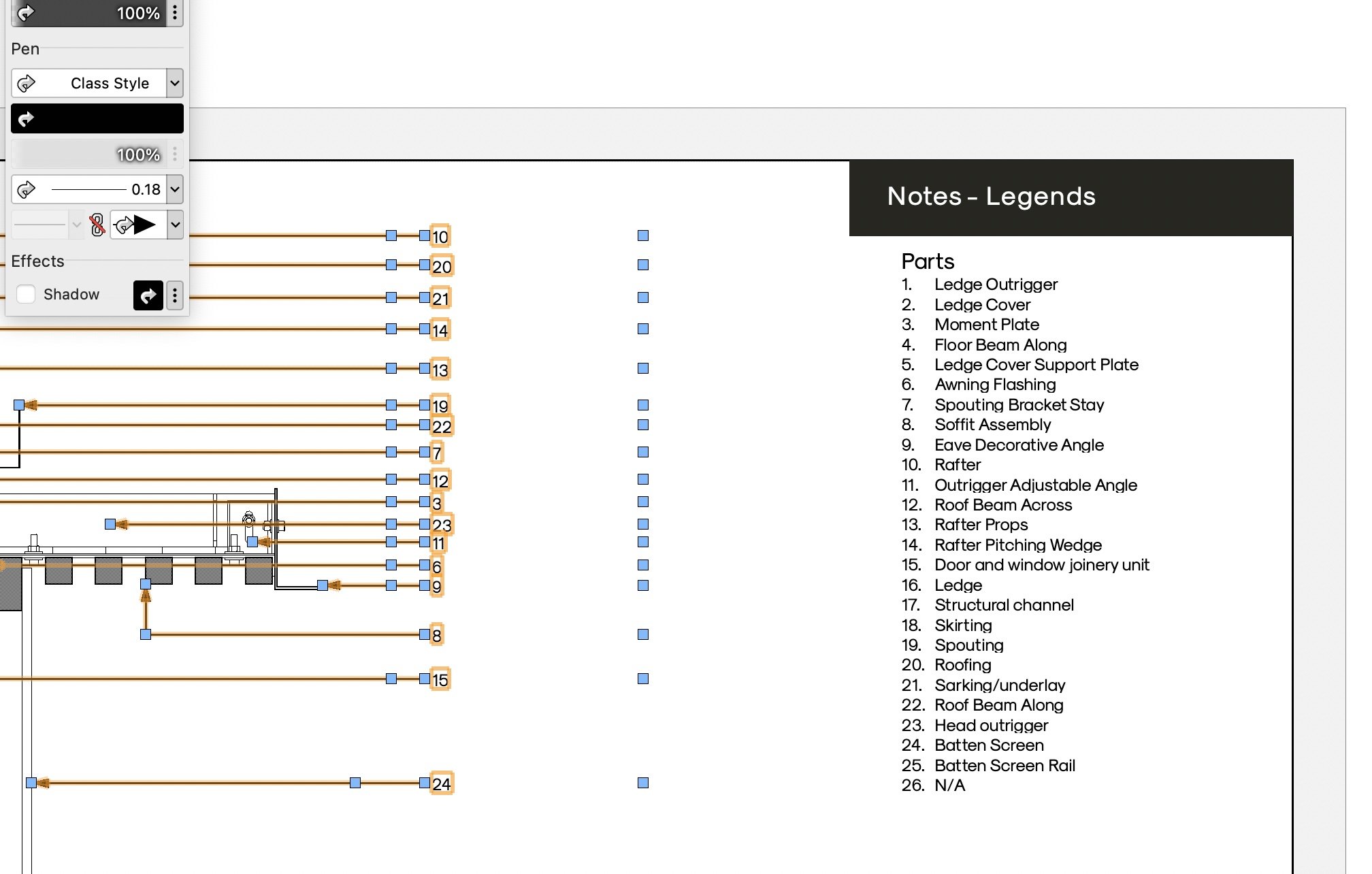
Indication of the symbol, materials, dimensions and in general records
Mat Caird replied to ShelterS's topic in Architecture
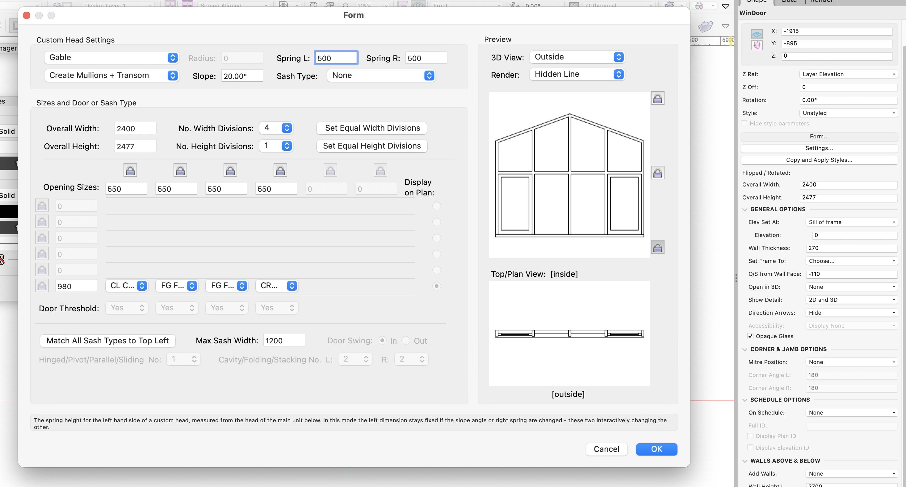
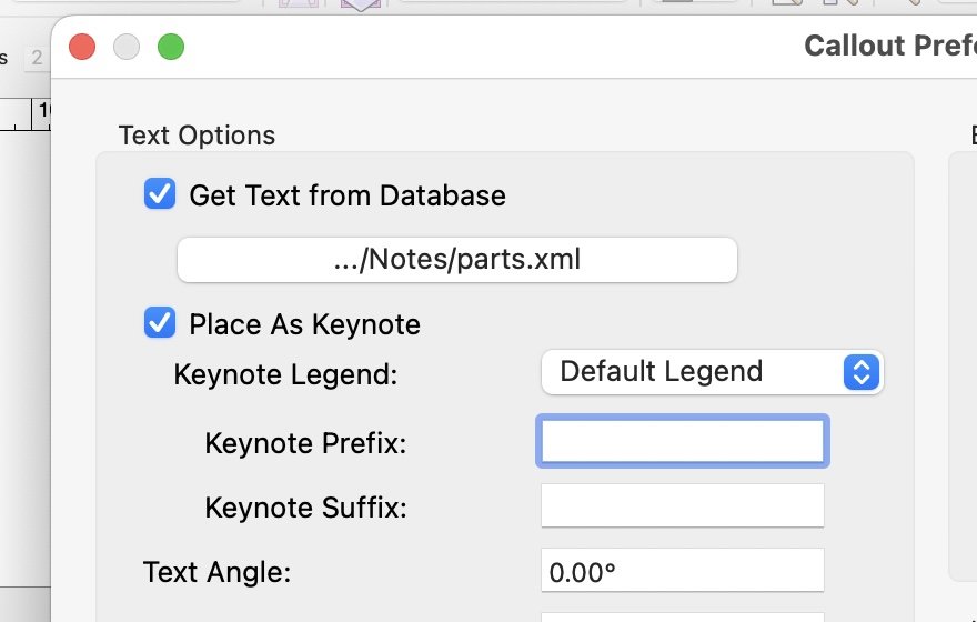
Is this what you mean; If so, then use the callout tool, with "Get Text From Database" You'll need to build your database manually. The first time you place the callout, the Keynote Legend will get automatically inserted onto your drawing - might be off the screen somewhere so you'll need to look around for it.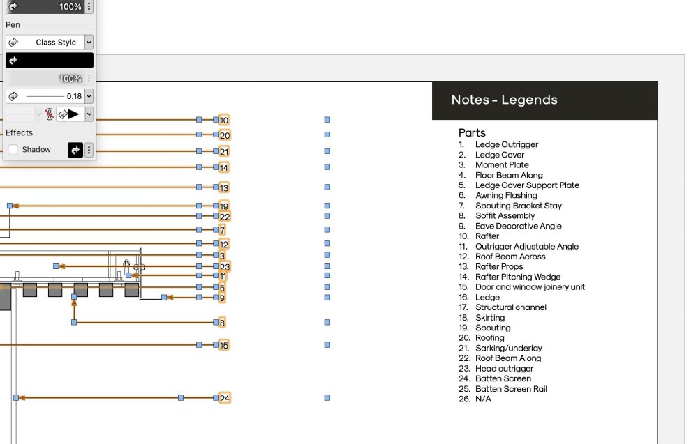
-
Escalating RAM usage on small files making Vectorworks 2022 Unusable
Mat Caird replied to Jack2022's question in Troubleshooting
I had a similar problem on my M1 MBP 32GB. VW would work fine until I updated a particular viewport. Then all aspects of VW would become unusable until I restarted VW. I found the problem to be some "climbing holds" I'd downloaded. They were 3d meshes, converted from sketchup I believe. Funnily enough, in the model layers where they resided, everything worked normal. It was only after updating the viewport (section viewport, shaded rendering) where the bug occurred. I solved this by deleting the climbing holds 😞 I didn't bother submitting a bug report.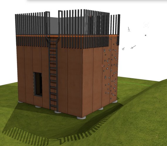
-
Detail callout tool issue
Mat Caird replied to hollister design Studio's question in Troubleshooting
I found that in an existing file, when I drew the detail callout, it created on a 3d plan. If I changed to Layer plane, I was then able to "create detail callout". When I created the detail callout in a new black file, I t created on a layer plane, and worked as expected. Mat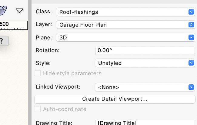
-
I found this post, and tried some of the suggestions, but still no luck; I have to admit I was too cheap to pay the $99 that the font converter I found was demanding. SO I did try using free font converters.
-
I'm having the same problem - does anyone have a solution?
-
Open Recent should update as soon as you open a file, so that when VW crashes, the file you were actually working on is at the top of the list 🙂
-
Method 2; Model both houses and draw all the details in one file. Import the surveyor’s 3d model of both sites. Use design layer viewports to position the house model correctly on both sites. Set up your sheets as usual, all identical except the site plan, and drainage plan sheets, elevations, and maybe sections if the terrain is different enough. Use the publish command to save sheets for house 1, and sheets for house 2. I found my building inspector was unable to work on one file for both houses, so I had to lodge 2 separate files for the ‘permits’. The drawback with this method in my case was the "99% the same" myth. In my case there were enough differences that the building inspector kept asking more and more questions it wasted months. There are other complicating factors in my case which may not apply to you. I just felt method 1 was easier to understand. For my simple brain.
-
I have done this a couple times. Method 1. House 1. Model the house and set up all your normal sheets; site, plan, elevations, sections, schedules, typical notes. Save this file as ‘house 1 model" Make a new file for the 2d construction details. Manually annotate the "house 1 model" sheets with the detail references Copy "house 1 model" and rename it "house 2 model". Alter the garage and property lines, drainage, height restrictions. The reason I did it this way is because of the way our ‘government building agency’ processes ‘permits’; the architect lodges the plans, the building inspector reviews the plans, then sends an email "requesting further information". In my experience, most of the difficult questions relate to the 2d details (we do high end custom houses). So changes made to the 2d file get easily incorporated into both houses. ‘The drawback to this method is manually referencing the details (which we used to do a few years ago anyways). Also, any changes to the model files you’d need to conduct on both files. I had consider various design layer viewport options but I find it hard to go back a few years later and get my head around how I’d originally set it all up. Plus, if someone else were to try and work on it they’d be potentially confused.
-
Applying materials to generic solids and extrudes, how to?
Mat Caird replied to LarryO's topic in General Discussion
This YouTube may help you -
I like that your client, a Pharmacist, can afford to develop a quality building, and supports good Architecture. Good work. Here attached a pharmacy in my home town for comparison;

-
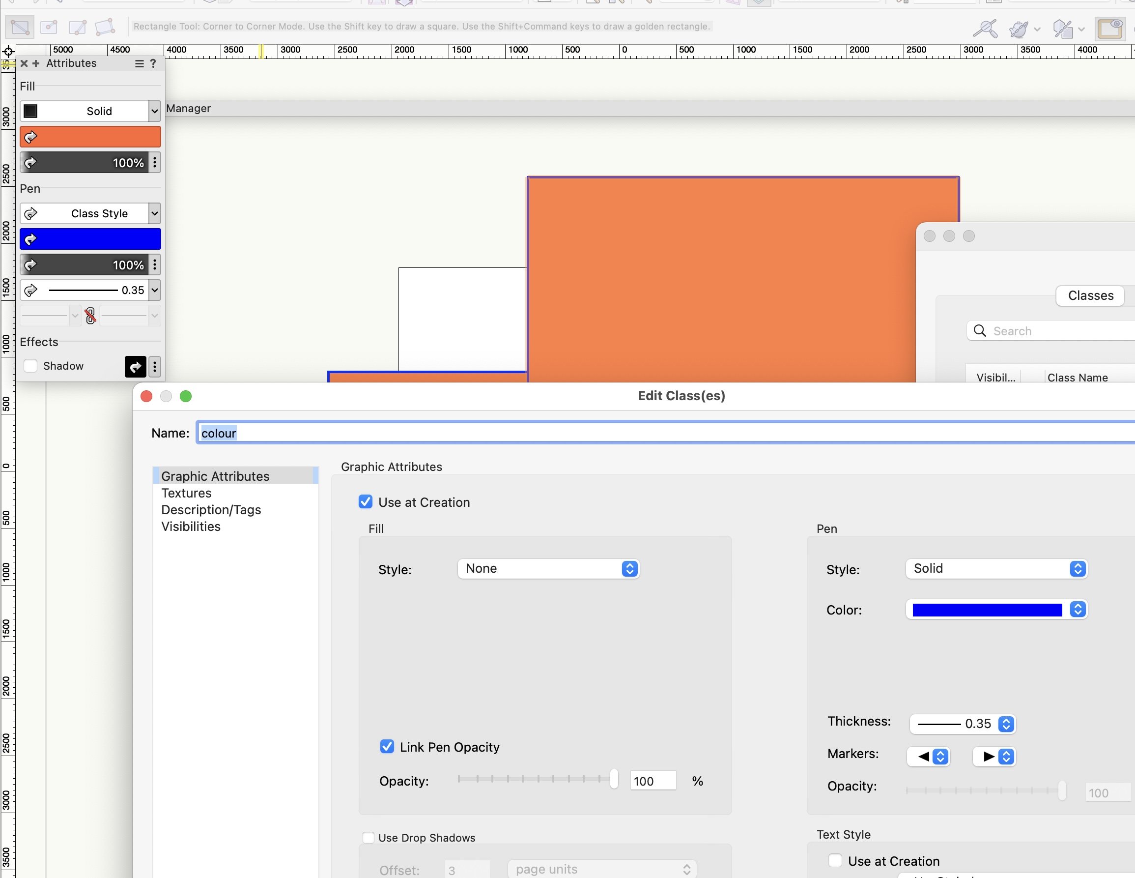
It looks like a bug; with nothing selected, change the default fill to a solid colour create a new class, you'll see the solid colour defaults to the fill of the new class tick use at creation change fill style to none click OK draw a rectangle, change it's class to the the new class you created, and as expected, the fill will be none in the attribute pallet, change the fill style to solid, and it will change to the colour you set as default - this is to be expected. Bug one - the OIP will show the fill colour as "by class" (ie the arrow in the colour box), yet you have not set a fill colour by class. Not a big deal really. Bug two - with nothing selected, change the fill colour default to something else. now set your rectangle to "make all attributes by class" (the 3 lines beside the question mark on the OIP). now change the fill style to solid, and it won't chose the new default colour, rather the previous colour you selected in step 1. You can open the Organization pallet and change the fill to solid, select a new colour, then change the fill back to none, exit the pallet and your items on that class will change to the newest colour, even though use at creation is on, and fill style is set to none. You might wonder how I've had the time to answer this question, and it is because I'm waiting for that dog software Revit to print a set of drawings to PDF. Mat

- 1 reply
-
- 1
-

-
It seems to work when you first create a symbol, but once you start adding items (maybe a nested symbol), it fails.
-
Hi All Why does "Center on objects after view change" not work when editing a symbol? Thanks in advance. Mat

-
How can I show a rustic render (stucco) finish for a house?
Mat Caird replied to David Gregory's topic in Architecture
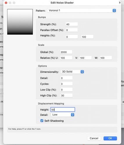
You could try creating a texture with a displacement map - you'll need to render in Final Quality Renderworks to see it. Here's a teaser - I spent 5 minutes on this. One render is OpenGL / shaded, the other I've applied the texture to the wall, and Final Quality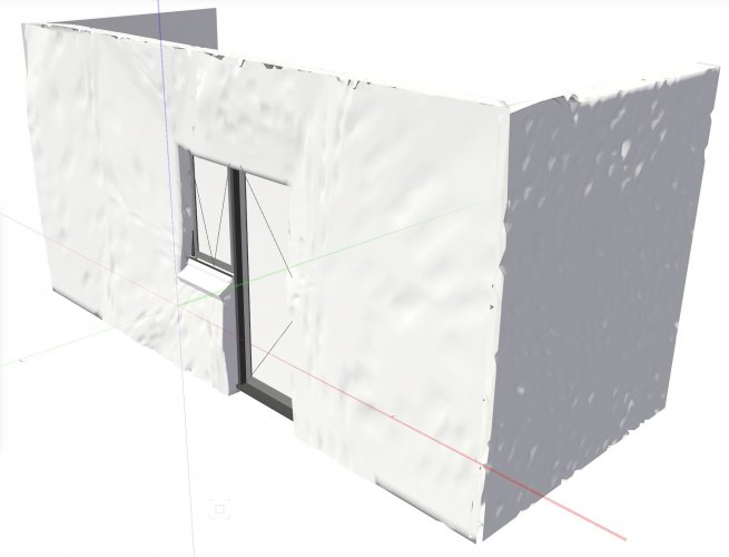

-
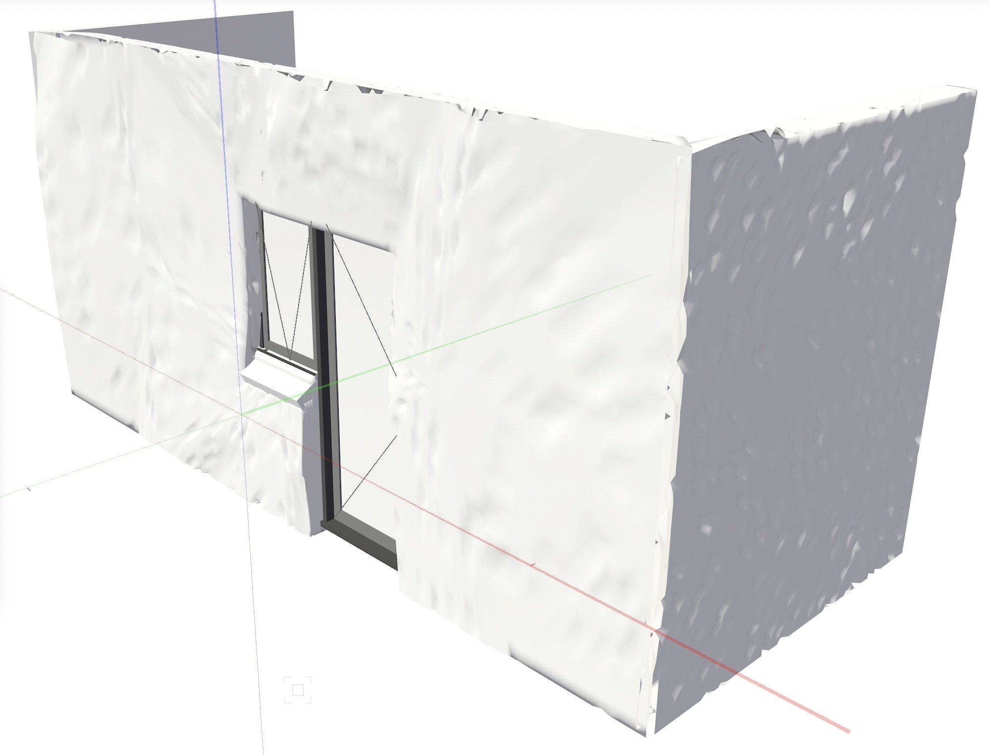
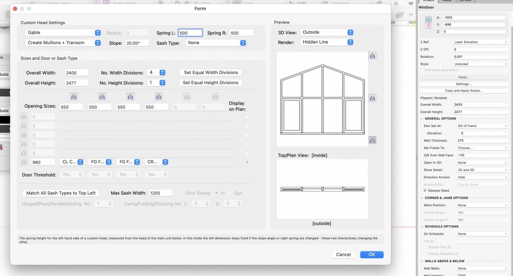
Hi KenH I got to here then gave up. My next step would be "convert to 3d polys", then manually draw to top arrangement. Then create a symbol so it will insert correctly into the wall. Convert to 3d polys generated a lot of items, so maybe just draw the elevation manually using polygons, then extrude. Then make a symbol. These workaround methods won't show a window on a default worksheet, so you'll have to workaround that to if you use the schedules. HTH, Mat
-
Thanks zoomed, it looks terrible on a 16" MacBook pro with retina screen.
-
Hi All Do any of you Mac users know how to get the Twin Motion user interface to scale correctly on a hi res MacBook Pro screen? And who in 2021 is using low res screens for goodness sake! Thanks, Mat
-
Maybe I shouldn't have refereed to force-quitting as crashing. Perhaps if I'd waited long enough the hidden line render would have completed.
-
My model featured many curves (the steel sections are curved in plan), so maybe that caused rendering delays.
-
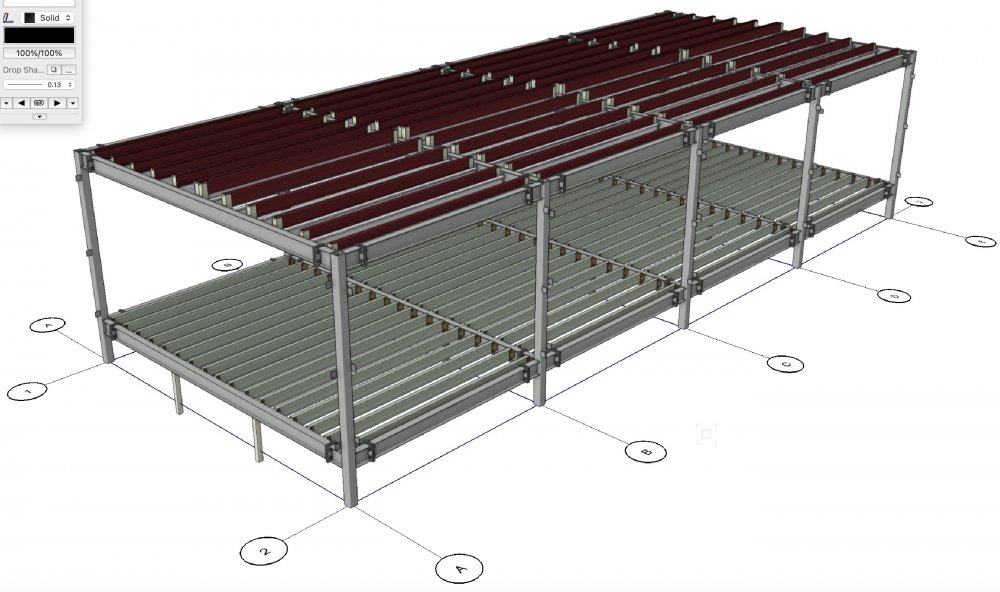
I didn't think so - only one design layer. File size 39MB. I built the model using symbols, mirrored, rotated, etc.Here's the open GL rendering of the section I was trying to render hidden line. I've basically given up on hidden line rendering, it was just a mistake to choose the wrong option when I created the viewport.
-
Force Quit 3 times yesterday, using Creat Section Viewport with hidden line rendering. Hadn’t crashed at all in the last week. I find the latest update to be for more stable than earlier updates.
-
Thank you BDC, and others, yes that worked.
-
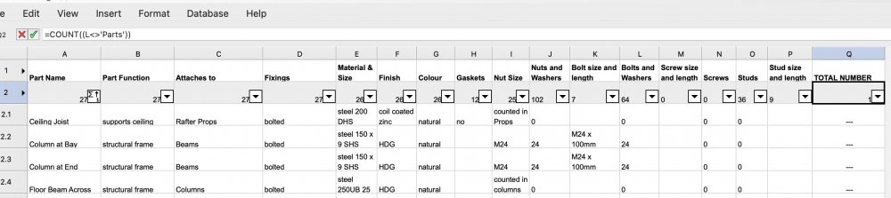
Thank you guys. Where / how do I insert the criteria? I tried this in the cell where previously =COUNT was located; =COUNT((L<>'Parts')) What is the correct syntax please?
-
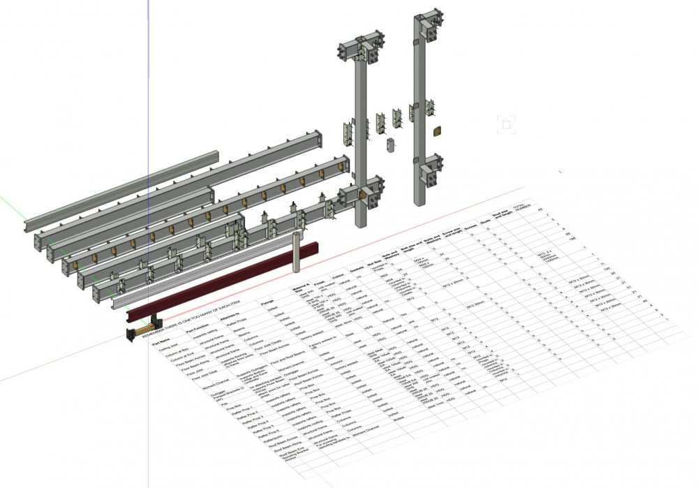
Hi All - I need some help with Worksheets and Record Formats please; I have a file with 2 design layers; "Model", and "Parts List". I have built the model using custom symbols, all of which have a record attached. On the design layer "Parts List" I have a worksheet to list all the part names (a record attached to each symbol), and also a single instance of each symbol. When I use the =COUNT function in the worksheet, it sums all the symbols with the same part name in the drawing, ie all on the Model layer, plus the additional symbol on the Parts List layer. So I need a worksheet calculation =COUNT-1 but this doesn't work for a database worksheet. Or I need to include only the instances on the Model layer in the =COUNT, but I can't get this to work either. Or I need a new spreadsheet worksheet that takes the data from the =COUNT column of the database worksheet, and subtracts 1, but I can't get this to work. I could workaround by deleting the extra symbols on the Parts List layer, but I want to avoid this if possible. Or maybe a design layer reference to a new file, etc, etc. There are workarounds I could try. But =COUNT-1 is my preferred approach. Any ideas please? PFA. Thanks in advance, Mat.