mike m oz
-
Posts
4,878 -
Joined
-
Last visited
Content Type
Profiles
Forums
Events
Articles
Marionette
Store
Everything posted by mike m oz
-
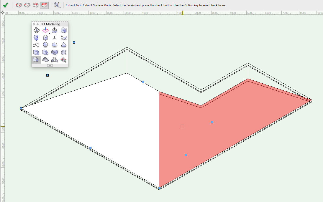
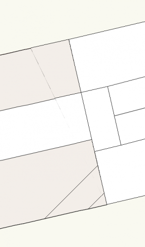
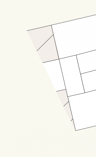
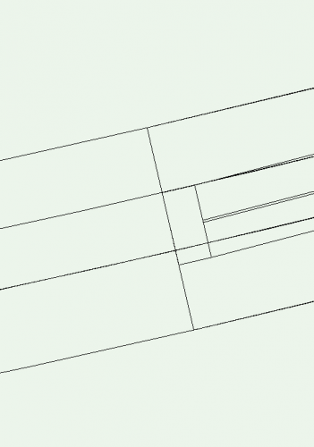
"unfold" roof to obtain actual roof size and run
mike m oz replied to O Design's topic in Solids Modeling
If you need the surfaces as graphic elements then use the Extract tool in extract surface mode. In too preferences set the mode to planar surface. Each surface can then be rotated in a side view by the roof pitch so it is parallel to the Ground plane.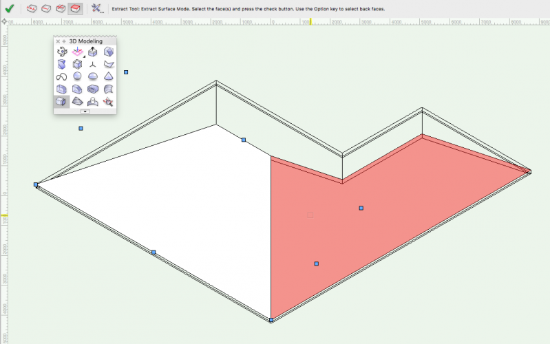
-
Where to upload some 3d Furniture I created
mike m oz replied to Kevin K's topic in General Discussion
Try Zipping the file and then uploading it. -
Where to upload some 3d Furniture I created
mike m oz replied to Kevin K's topic in General Discussion
I don't know if there is a file size limit. The Symbol Resource Sharing Forum would be better if it had sub-categories so users could then more easily refine their search. A search link from the program to the Resource Sharing forum would also be very useful. -
Where to upload some 3d Furniture I created
mike m oz replied to Kevin K's topic in General Discussion
There is a resource sharing part of this forum. https://forum.vectorworks.net/index.php?/forum/5-resource-sharing/ There is also the third party sharing forum of Vector Depot. It used to be the place but very few users are aware of it now. http://www.vectordepot.com -
Export each Sheet Layer as a separate DWG file. Uncheck the 3D options.
-
Are you exporting from Sheet Layers and using the option to Export Viewports as 2D graphics in Model Space?
-
The 2D version is the default. Nested underneath it is the 3D version. Click on the object icon and hold the mouse button down. That will then allow you to select the 3D version.
-
Edit your Dimension Class so it has no fill and the Graphic Attributes are set to Use at Creation (check mark box at top left).
-
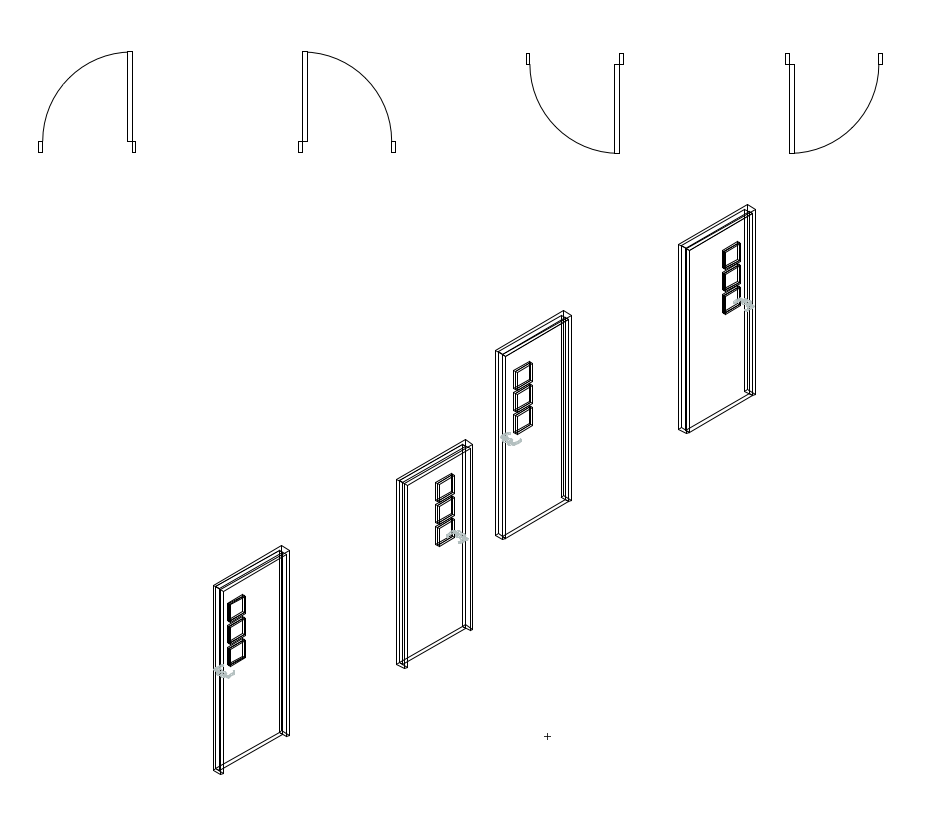
Having to create a hybrid symbol to do this is time consuming and hopefully this will be remedied in the near future. STEP 1. Create your own 3D geometry. STEP 2. Create your own 2D geometry. STEP 3. Create 2D wall patches at each end. STEP 4. Work out your insertion point so the symbol inserts in the wall at the correct location and orientation (the not fun part and you will probably need to do it by trial and error). STEP 4. Select all the 2D and 3D and create a symbol from it using the insertion point. STEP 5. Create a custom Wall Hole Component so you can get the 3D hole in the wall correct. Hybrid Window symbol in Round Wall v2018.vwx
-
Tine, the only way you can do this is by crating your own hybrid symbols. If you can say what version you are on I can post a file with an example in a curved wall.
-
Jim, your presence on the techboard and audio voice overs in many of the feature and training videos will be missed. For many of us you have been the public face of Vectorworks for years and you leave big shoes to fill.
-
Dormer, can you please post a 2D image of what you want and also tell us what version of Vw you are using.
-
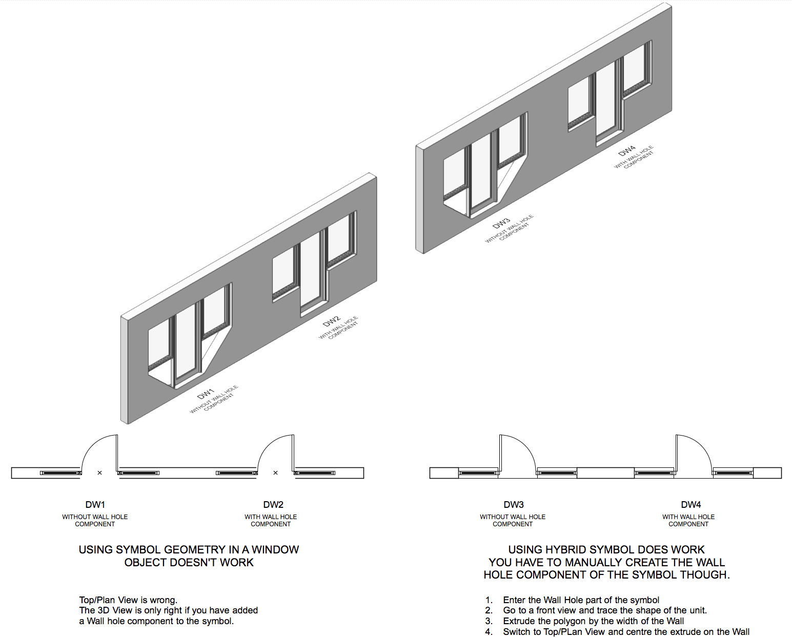
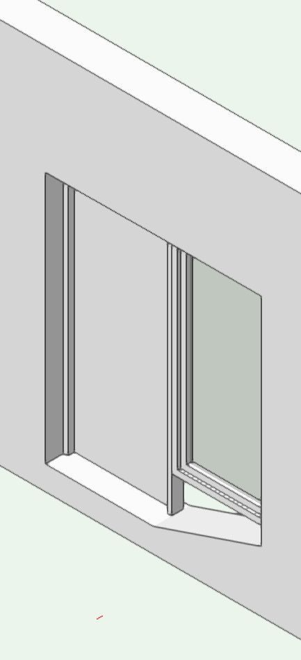
See if you can make sense of this. METHOD - to create DW4: - Assemble the units as you want them. - In Top/Plan View add 2D linework to get the required plan view (wall lines and the like). - Select all of the components and create a hybrid symbol. Make sure you use an insertion point that will centre it on the Wall. - Edit the Wall Hole component of the symbol and create an extrude to cut the wall as required. Wall Hybrid Symbols v2019.vwx Wall Hybrid Symbols v2018.vwx

-
Years back I did a Wish for the ability to gang windows and doors together without the wall break lines between adjacent units in plan views. It was suggested that the solution was to create a custom symbol so there are only the Wall break lines at each end. Yes that does work but there aren't many users who know how to do that and you won't find instructions on how to do it in Help. I agree with you HMichael that the program should be able to do it. The 3D isn't a problem. It is only the 2D Plan View that is a problem and it seems that all that is needed is a choice of options to have both Wall break lines, Left Wall break line only, Right Wall break line only and No Wall break lines.
-
Vectorworks User Interface Overhaul
mike m oz replied to Thomas Wagensommerer's question in Wishlist - Feature and Content Requests
I agree Matt. Provide a no color option for those that want it but don't impose it on the rest of us. Personally I'd prefer the effort went into improving functionality instead of the latest fad appearance. An appearance that is likely to date very quickly. -
Create Roof Face objects for each roof plane (AEC menu).
-
The only flipping in the wall should be to define which side of the wall is the outside face of the door. Whether the door opens in or out and whether it is left hand or right hand should be parameters. Windows should have similar parameters so flipping within the wall is not necessary. When a door or window is selected there needs to be a marker that identifies which is the outside face.
-
That is a solution that won't be obvious to many users. Surely it would be better to not have work arounds or flipping. Have the real word options for: - left and right hand doors. - doors opening in and out.
-
It could be fixed by adding the ability to have doors open in or open out.
-
How to flip a door that's not attached to a wall?
mike m oz replied to lponesse's topic in Architecture
Use the Mirror tool on the Basic drawing palette.
-
Wall line in between adjacent window and door
mike m oz replied to flamingzip's topic in General Discussion
It only occurs in Plan View and there is no way to not have it. There have been repeated requests to allow 'ganging' of doors and windows but to no avail. The workaround is to make symbol of the ganged Door and Window objects. This will insert into the wall without the opening cap where the objects are in contact. You will however need to edit the 3D Wall Hole Component to get the correct hole in the wall in 3D.
-
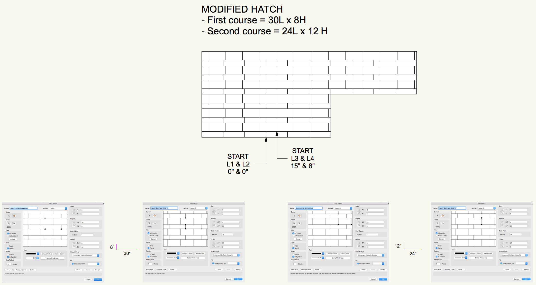
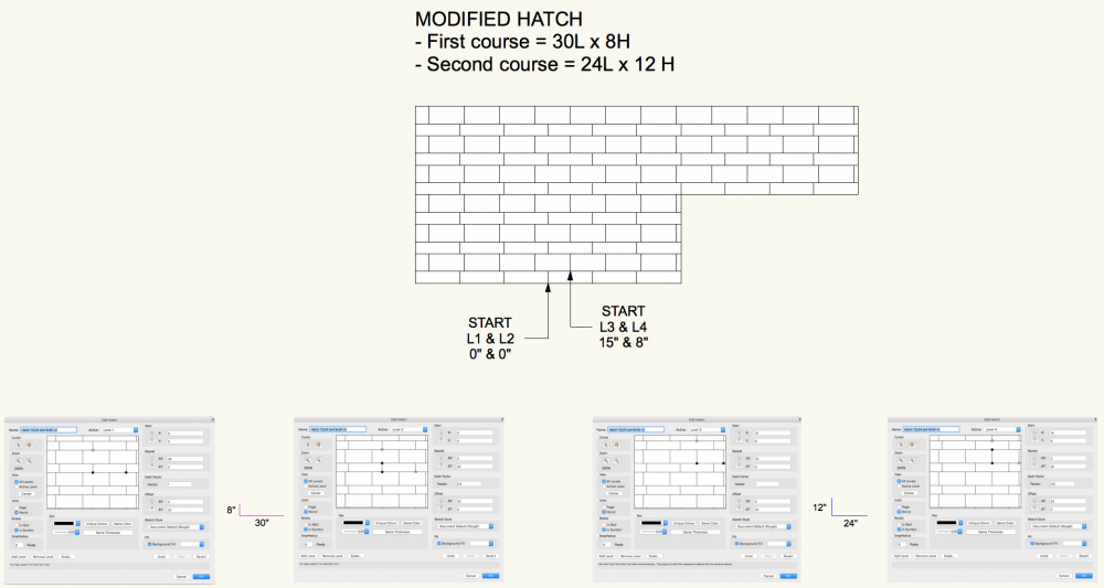
I''ve revised the hatch making your 8x30 the first course with the 12x24 the second course with its start point at the centre top of the first 8x30. The best way to understand this is to plot each layer on graph paper using a different colour for each layer. For a simple hatch like this use the orthogonal mode: - Levels 1 and 3 are the horizontal elements and are continuous so their dash factor is 1. - Levels 2 and 4 are the vertical elements and are intermittent. Their dash factor is 0.4 (8/20) and 0.6 (12/20) respectively. LRe Hatch Imperial v2019 rev.vwx LRe Hatch Imperial v2018 rev.vwx
-
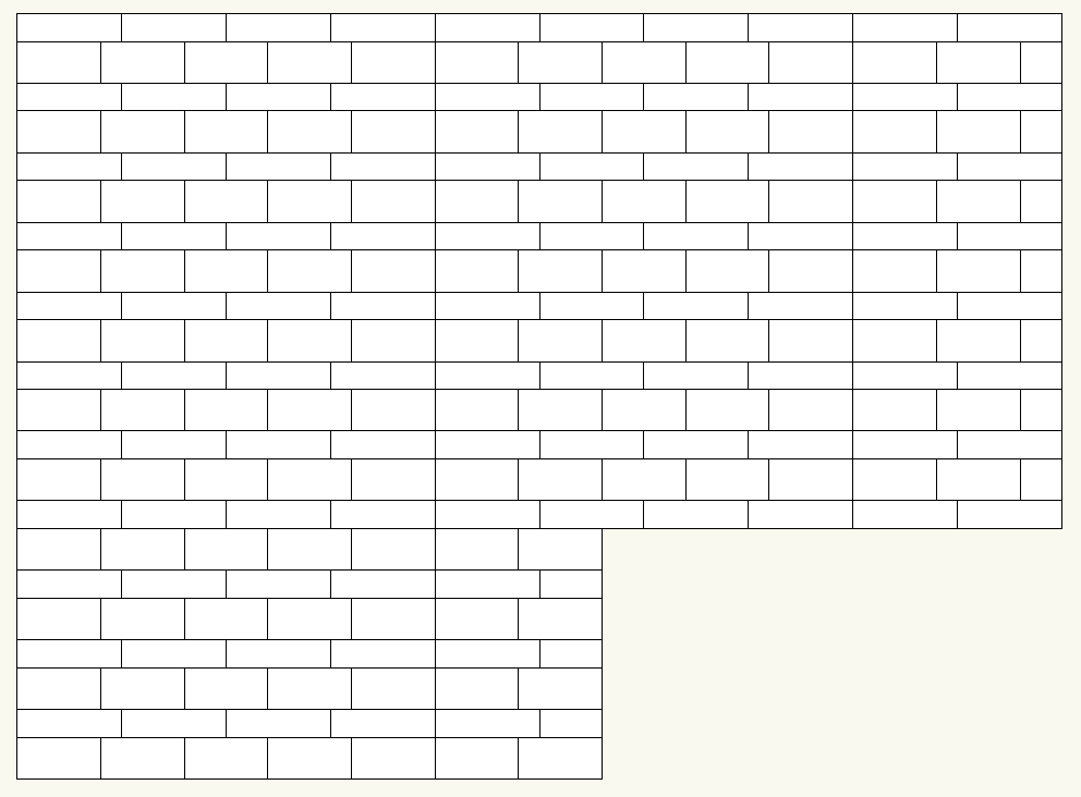
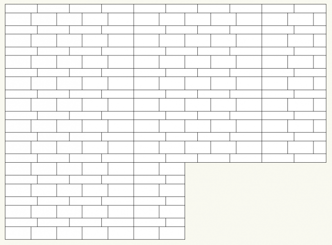
Without knowing the start relationship I've made this imperial version (ie. inch units) of what I think you have described. As you will see from the repeating vertical line the start relationship of the two patterns is very important. LRe Hatch Imperial v2019.vwx LRe Hatch imperial v2018.vwx
-
LRe, provide an image of what you want and I'm sure someone will create the hatch for you or tell you how to do it. Your word description of "one row of 12x24 pieces and second row of 8x30 and have that repeat over and over again" doesn't provide enough information. To create your hatch it sounds like you need just 4 layers. - Layer 1 is the base of the 12x24 pieces. - Layer 2 is the first vertical of the 12x24 pieces. - Layer 3 is the base of the 8x30 pieces. - Layer 4 is the first vertical of the 8x30 pieces. The spacing of each horizontal line is straightforward. Its dash factor will be 1 and its offset the distance it repeats at vertically. The spacing for the vertical lines is also straightforward. Calculate its dash factor vertically and then its width becomes its offset distance horizontally. The start point for each element is critical and you need to work out the relationship of the two at a particular point. Once you know the geometric relationship of the two elements at the start point the rest is straightforward and just simple maths.
-
It would be useful to be able to draw a 2D pattern and then invoke a command to create a hatch from that 2D linework.