halfcoupler
-
Posts
461 -
Joined
-
Last visited
Content Type
Profiles
Forums
Events
Articles
Marionette
Store
Everything posted by halfcoupler
-
Yes this is something I'm deeply missing in VW, there should be a way to direcly create a 2D Linework form a Section by clip cube. I prefer Hans-Olav's workaround and use it a lot: - create a section vewport, export it as flattened 2d to .dwg, re-import this to an empty VW file, dissolve all groups and symbols and try to purge all coincident lines.
-
try these settings that influence the appearance of GL viewports: - in the object info pallette there is "Backgrund Render Settings". If it is set to "low", circles appear more as polygons, "very high" makes all curves smooth, but increases the size of the file when exporting - the sheet layer itself has a setting for resolution. ( Right click on the sheet layer in the Navigation palette, "Edit...") If it is set to 72 DPI it gets blurry, for a clear Open GL you should use min. 200 DPI, better 300 DPI, but this also increases the size of the file when exporting. Hope this helps ....
-
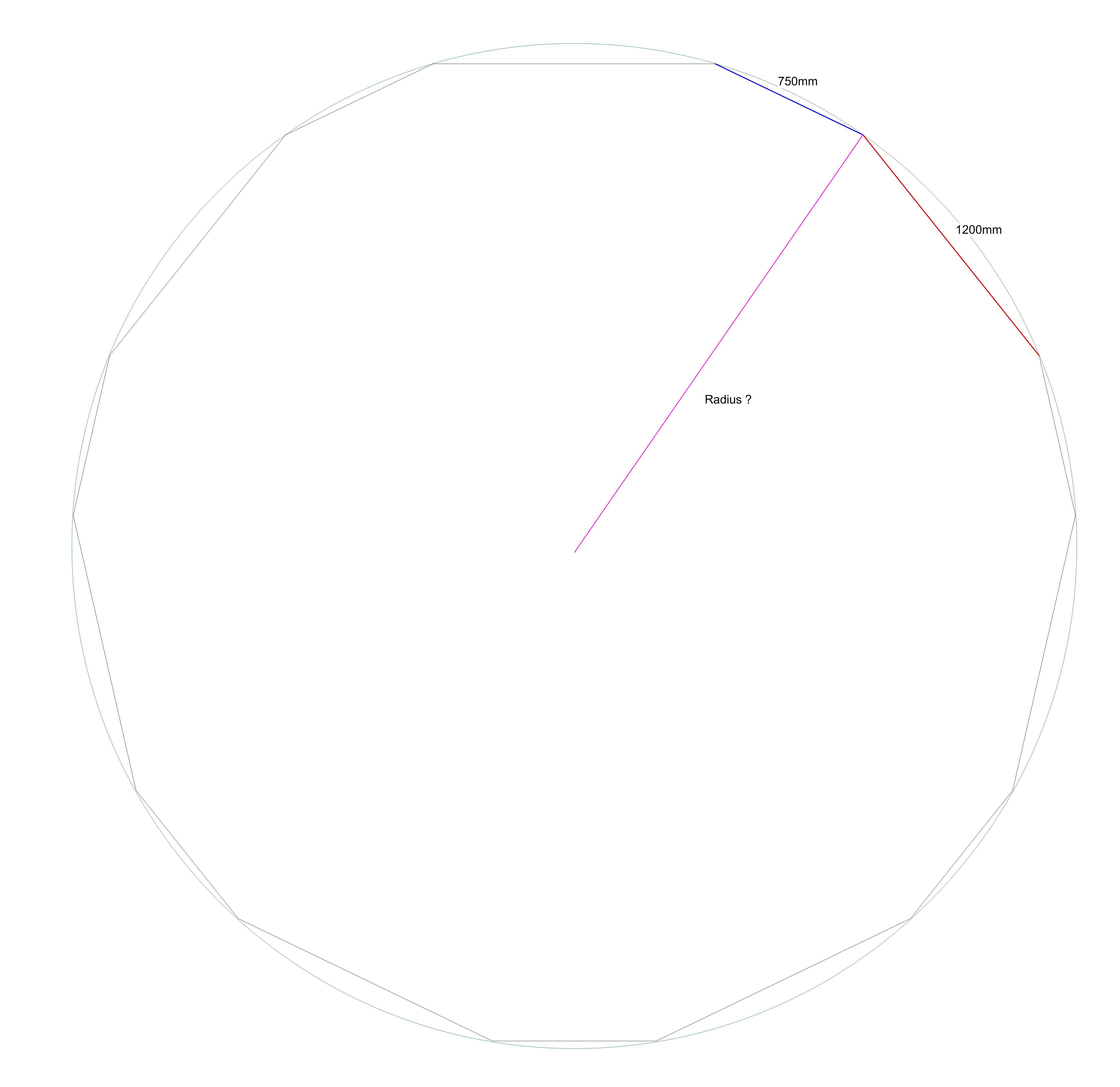
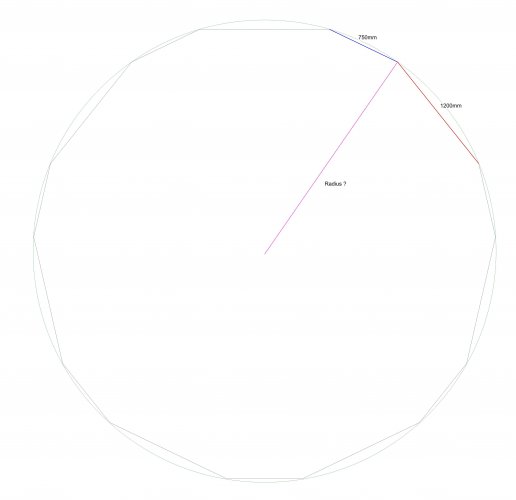
 Hi Guys, thanks so much for the help ! Think I never got the solution alone. I need to do this with different side lengths so 1200 and 750 are only an example. So the reproduceable method is to calculate the "double angle" Edges / (Edges/2 -1) / 360 and split it up by the proportion of the side lenghts. Two parallel lines for each side cross the angle at the desired radius. I will check that for other length combinations.
 -
This is more a mathematical question, but maybe someone knows a way to to draw this: I want to draw a closed regular polygon of 15 edges with alternating sides of 1200mm and 750mm. All I know is these two legths. The question is how to draw it, and is there a unique radius that matches the outer circle ? If yes, maybe someone knows how to calculate this radius mathematically ? ( I gut stuck in trigonometrical theorems in the end...)
-
Projecting 2D planar on 3D crossection in viewport on sheetlayer
halfcoupler replied to frv's topic in General Discussion
Don't know if I understand you right, but maybe this helps: - If you have a VP created from Clip Cube be shure to have the planar objects within the clip cube. Sometimes the projection of planar objects on screen plane are not located in the range of the clip cube section - for planar objects on Screen Plane you need to have "Project Screen Objects" on the OIP of the VP selected - for planar objects on Layer Plane you need to have "Display Planar Objects" on the OIP of the VP seleced. I have just tested it, and you are right, depending on the resolution planar (line) objects may appear "weak" in Open GL renderings, but thats seems not to be a problem of VP's created with clip cube. -
Viewport from clip cube not functioning
halfcoupler replied to Mike Wright's question in Troubleshooting
Sorry, sorry, please ignore my post. I located the problem between keyboard and office chair. 😯 Everything workes properly as designed. -
Viewport from clip cube not functioning
halfcoupler replied to Mike Wright's question in Troubleshooting
Section views from Cilp cube in Hidden Line worked with SP3 , now with SP4 they do not. Very bad since I use this not only a lot,- this has become part of my daily work. Will there be a SP5 soon or do I have to wait for VW20 to proceed my work ? 😕 -
anyone knows what was done ? Hidden Line Renderings seem to be 2 times faster ? Great ! 😀😀😀
- 1 reply
-
- 1
-

-
Hi markdd, thanks tor the tip and testig, but it seems to be not even halfway... I can edit the class in the plugin manager, but not permanentely, - this setting is lost as soon as the file is closed. Even saving this as template does not work.
-
Using the clip cube when creating sections leads to section lines /rectangles somewhere in the drawing. Their class and Layer is whaterver was activated when the section was created. I wonder if it is possible to give the section lines an automatic class like dimensions in the dimension class ? Anyone here has a workflow for this ? Having a "sectionlines"-class in the template and manually assign the section lines to it is one way. But anything more elegant ?
-
Why can you move axes in Symbol Edit Mode?
halfcoupler replied to Andy Broomell's topic in General Discussion
Hope I understood the question right... You can move the X and Y axis in order to define a new working plane. This does only affect the tools you are working with, but not the position of the objects on layer plane. Try to move the axis and then click on "look at working plane" button to see how it works. -
uups, got it,- it's simply the ALT-key ... ( on windows )
-
I think there was an option that symbols can be inserted to the working plane instead of layer plane, cant find it... anyone knows ?
-
Thats it ! I changed from png to jpeg for some testing reason a few days ago. When switching back everything works normal again. It seems that switching to jpeg toggels the rendering mode (on Windows). - When jpeg is active the RW Background is working in open GL and produces a black background when set to "None". - When png is active the RW Background produces a white background when set to "None", all others produce black. Bug or Feature ? 😉 Thanks much for Help! Georg
-
Just did some testing, you are right, this is something else: - Although it's an Open GL Rendering, it seems to respond to the Renderworks background settig, if none is selected then it appears black. ( But it should be white ) Setting the RW Background of the VP to "HDRI white" makes the Open GL rendering appear with white background as before. Maybe this is a change in SP3 ? - I have this issue with every file and every Viewport. At first I thought is is some settings in my template file, but it is the same with a blank document. Maybe I accidently changed some VW preferences, but I can't imangine which ones. Here is a sample file: Rendering Background.vwx Maybe someone can test it with other preferences settings, so I can be shure its my settings that are wrong ?
-
Today the black devil showed up again. No chance with duplicating the viewport. This is an open GL rendering. Something is definitely wrong here.
-
Progress is man's ability to complicate simplicity. Thor Heyerdahl
- 1 reply
-
- 2
-
-
No image effects applied, the problen does also occur with rendereig design layers.
-
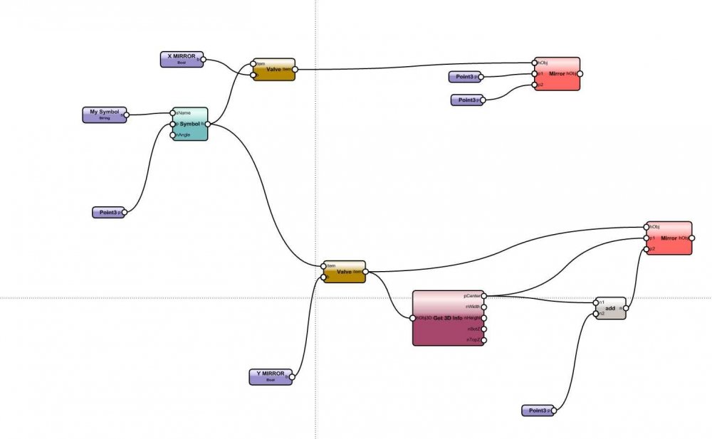
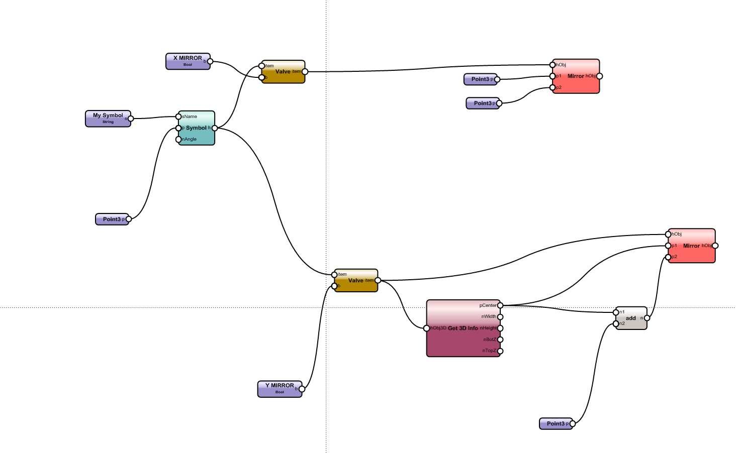
two or more Valve nodes, which one takes presidence ??
halfcoupler replied to halfcoupler's topic in Marionette
no problem @ IJSSEL , I love to see people being interested in my posts 🙂 meanwhile I have played around a bit, the problem seems not to be the valve node, but the mirror node. I have made a separate wrapper for YX mirroring and here the same problem appears: No effect on X-Mirroring when Y-Mirroring was done before. Next step will be to try with Flip nodes.... As soon as I find time for that. mirror.vwx -
I have the same issue with VW 19 SP 3.1. Not only with viewports but also when rendering design layers. Either changes are not acceptect, or it renders a black screen.
-
Wow ! using VW for 15 years now, never found that tool ! Great way to make "quick&dirty" cable plans for smaller jobs...
-
Can't hold me back from commenting this ( just some thoughts when I read this ) : I fear it's the opposite that is the unavoidable reality,- the computer does the drawing and we have to learn the language the machine understands. Creativity with drawing pictures is only when you use pen and paper. Don't know how others do that, but actually my projects always start with some ideas scribbled on a piece of paper. Maybe someone here starts with freehand lines in VW ? It's a crazy brave new world we are in. I fear we are the last generation that has the chance to understand what the machines do since the machines are not (yet) perfect with WYSIWYG. Later generations will only have WYSIWYG and they will belive that this is the real world.
-
two or more Valve nodes, which one takes presidence ??
halfcoupler replied to halfcoupler's topic in Marionette
Thanks Marissa, I diddn't think this was so complicated... Just thought that I could try to use the Flip3D node plus moving the object to the correct positon afterwards, to avoid mirroring. -
got it ! Thanks :-)))
-
I got stuck with this, maybe someone can help ? I want to create a marionette object that can be mirrored via OIP either on its x-axis, or on a center line parallel to y-axis, or both of them. The first of the two work fine, but I can't get a combination of both to work. The Valve node for mirroring the y-axis kills the x-axis Valve and vice versa. I wonder if Valve nodes are the best choice at all for this task... mirror.vwx