line-weight
-
Posts
3,756 -
Joined
-
Last visited
Content Type
Profiles
Forums
Events
Articles
Marionette
Store
Everything posted by line-weight
-

Layer Scale question - why not just 1:1?
line-weight replied to yasin2ray's topic in General Discussion
I was wondering yesterday if I should update the 3DC driver, sounds like I'd better not! This is what I'm currently on: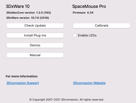
-
Multiple View Planes - ability to "lock" a view
line-weight replied to livespace josha's question in Wishlist - Feature and Content Requests
Please can we also have the ability to properly set up a workspace with a pane on a second monitor. -
Layer Scale question - why not just 1:1?
line-weight replied to yasin2ray's topic in General Discussion
Ah yes - I can see how this could be useful during the editing/drawing process. -
Layer Scale question - why not just 1:1?
line-weight replied to yasin2ray's topic in General Discussion
. -
Layer Scale question - why not just 1:1?
line-weight replied to yasin2ray's topic in General Discussion
Another thing that might be relevant to all this... 20 years ago I worked in a practice where we would routinely produce drawings at A1 size... they'd go to a commercial printer and big bundles of paper drawings would be taken off to site in the post or by a delivery driver... That meant you could produce quite detailed general arrangement plans at fairly large scale even for quite big buildings. And put quite a lot of different types of info on them. They would be rolled out on a big table at site meetings. Now, at least the way I work, for myself, I produce most of my construction drawings at A3 size, so I can print them myself on the printer by my desk, but in fact half the time they never exist on paper and everyone is looking at them on laptops or tablets or maybe even smartphones now. So this has implications for how it makes sense to set up drawings, and means more flipping between different scales for different bits of information. Typically my drawings sets now have a larger number of smaller viewports at a wider range of different scales. And of course the approach of extracting the 2D drawings from a 3D model makes this less labour intensive than it would have been in the past. -
Layer Scale question - why not just 1:1?
line-weight replied to yasin2ray's topic in General Discussion
No, I've never used or wanted associative dimensions. To me, they are more likely to cause errors. For example, one becomes un-associated but the user doesn't notice, and is not in the habit of re-checking viewports before publishing. For me it is a good discipline to make the change to the model geometry, then check the viewport and make adjustments and make sure they are correct. Also, there is the potential for it to appear in a design layer view that it is clear what a dimension is to or from, but then in a viewport it's not, because some components might be turned on or off, or a different scale means something is obscured by lineweights. You can see these kinds of things creep in when a dimension is intended for wall framing, for example, but then is present in some viewport where it appears it refers to the finished wall surface, this kind of thing. -
Layer Scale question - why not just 1:1?
line-weight replied to yasin2ray's topic in General Discussion
Sure. Everyone will have their own approaches. I have a quite strict/minimalist philosophy when it comes to dimensioning. This means that there are only dimensions where there really needs to be dimensions, and in an ideal world the same dimension shouldn't appear in more than one viewport. Reference grids and height benchmarks appear in every drawing (and VW now finally gives us the tools to do this properly - hooray!) and dimensions generally refer back to them. I'll have a setting-out plan which will just be focused on setting out, and another plan that focuses on what's important at a later stage of construction. The other thing is that to keep things graphically consistent and neat, I get much more control when things are in the annotation layer (rather than the compromises that tend to be needed when pulling certain things through from a design layer). I feel that many architectural drawings are vastly over-dimensioned. This results in cluttered drawings but also often reveals a lack of thought about how things will get set out on site. And often leads to errors, because the critical dimension is not made clear to the builder. Of course, that's architecture and I'm sure entertainment and other industries will have different needs and priorities. -
Layer Scale question - why not just 1:1?
line-weight replied to yasin2ray's topic in General Discussion
Yeah, last time I fiddled with things, this didn't turn it down slow enough. But that was a few VW versions ago, and probable a few 3dconnexion driver versions ago, so it might be worth revisiting. -
Layer Scale question - why not just 1:1?
line-weight replied to yasin2ray's topic in General Discussion
This just doesn't really work for projects where output drawings might range in scale from 1:5 to 1:100. Not for 3d workflows anyway. -
Layer Scale question - why not just 1:1?
line-weight replied to yasin2ray's topic in General Discussion
I set all my design layers to 1:1 because otherwise I have problems using my 3d navigator device. (Maybe I should review this, perhaps settings have changed since that was an issue) I never put dimensions, text and so on in design layers - always in annotation space - and most of my editing time is spent in 3d views, so the downsides don't affect me too much. These days most of my 2d drawing work is done within annotation space. Have said it before, but "layer scale" should be renamed to stop confusing everyone - call it "preset zoom" as @Pat Stanford suggests. And have it as something that can be adjusted on the fly and applied to everything you're looking at at a certain point in time, rather than having to set it for multiple layers.] It's a hangover from ancient 2d workflows, but I know it's hard to change these kinds of things without upsetting people who continue to use those workflows. -
2023 Benchmark Tool - How to display relative Elevations + NAVD88 Elevation?
line-weight replied to maxstk's question in Troubleshooting
The online help documentation doesn't seem to give us a full list or explanation of the various definition codes that we can use for "dynamic text" when making custom benchmark label layouts. We need this in order to get the most out of the tool. I've just managed to create a (relatively) simple one for my own use but it involved me having to do quite a bit of reverse engineering (and general trial and error) from some of the standard styles and the code that can be seen in the video posted further up this thread. (I wanted to set it so that positive elevations would have a + sign and negative values a - sign ... for the benefit of anyone else who happens on this, the code I used is below) "+"@#Elevation Benchmark2#.#Elev#>=0:""""@#Elevation Benchmark2#.#Elev#<0:""#Elevation Benchmark2#.#Elev##custom# -
2023 Elevation Benchmark: what controls the leader line length?
line-weight posted a question in Troubleshooting
I have made an elevation benchmark style. I've then applied some benchmarks, using that style, to a viewport by using the "elevation benchmarks" button in the viewport's OIP. These benchmarks are linked to story levels. This all works nicely, but how do I control the leader line length - the distance the benchmark sits away from the viewport crop box? There doesn't seem to be any control of this in the style settings. And it's not part of the "marker layout". Do I have to go in to the viewport's annotation space and adjust all the leader line lengths manually?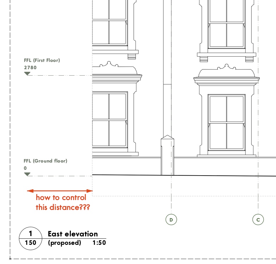
-
Structural Member usability improvements
line-weight replied to LarryO's question in Wishlist - Feature and Content Requests
Yes, it feels like it's not something that would be too complicated to add so perhaps we will see it some day. On the other hand, the unpredictable behaviour of auto-connected members shown in my video in the post above, is more problematic and I would describe as a bug. I think this tool may now be usable for me but only with auto-connect mostly turned off. Definitely an improvement compared to a couple of years ago though.- 16 replies
-
- 1
-

-
- structural
- steel
- (and 2 more)
-
VW Architect Lights help and explanation
line-weight replied to MGuilfoile's topic in General Discussion
We have! -
Structural Member usability improvements
line-weight replied to LarryO's question in Wishlist - Feature and Content Requests
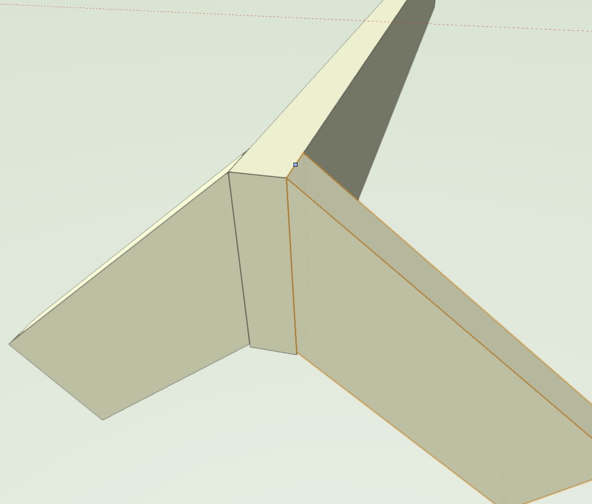
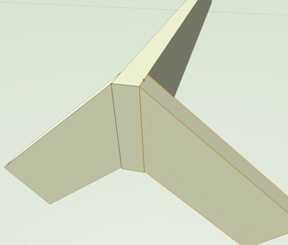
And another thing... The OP mentions the reasons why a "top" reference axis is usually most useful, because that's how structural members are often set out (the thing that really needs to be at the right height is the top, because that's usually what something else is sitting on). This applies to timber as well as steel. Ok, so you can choose to have "top centre" as you axis. And now you can have styles, you can make that part of a style if you want, so it's effectively the default behaviour. But then there is a problem with the way auto connect works - say you are connecting rafters to a ridge beam. You get this: I understand why this is - the top-centre axis of the rafter meets the top-centre axis of the ridge beam. Where the little blue square is. But that's not normally what you want constructionally - you're more likely to want this: And to get that, the rafters have to be positioned manually. Ideally the start or end condition of any connected member ought to have a choice of where its axis meets the member it's joining - does it meet it on axis, or does it meet it at its outer edge (or indeed at some offset, vertically or horizontally, from either of those).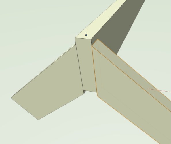
- 16 replies
-
- 6
-
-
- structural
- steel
- (and 2 more)
-
Changing the conversion resolution can make this problem less bad but I wouldn't be surprised if the OP already has it on high. The larger the radius of the curve, the more of a problem this is. This faceting of curves is a quite big limitation of Vectorworks if you are trying to do certain things. There is some fairly detailed discussion of it here:
-
This! One of the first questions should be: will I want to edit this after I've drawn it. Do they need to be shown as multi-component in section. Etc.
-
"Framing member" vs "structural member" tools
line-weight replied to line-weight's topic in Architecture
So I tried it out a bit in VW2023 SP2. Have added comments to the main structural member usability thread to try and avoid too many parallel discussions going on. -
Structural Member usability improvements
line-weight replied to LarryO's question in Wishlist - Feature and Content Requests
Ok, so having complained about the structural member on another thread, based on my experiences in VW2021, @Matt Panzer pointed out that several improvements have been made since them, and some of them address points raised in the OP of this thread. I've now messed about a bit in VW2023 (which I've not yet started using for real) and can see this. This is good - and some of these changes greatly increase usability. However ... a couple of issues I'd like to raise (and willing to be told I'm missing something in either case). 1. We need a graphical clue which is the "start" and "end" of a SM, when it's selected. Otherwise it's guesswork whether we need to edit the start or end condition. Don't we get a little starter triangle with walls, for example? 2. I also want to be able to "reverse direction" like with walls. For example, if I am setting out by pitch angle, I'll typically want to do this from one end and not the other. I might want to adjust the pitch of an already-existing member, one end of which is in the right position, and which turns out to be the "end". 3. As far as I can see, there's not any way of changing an already-connected member to an unconnected one, other than a roundabout process of activating the SM tool, deselecting the "auto join members mode" button, resizing each end of the member you want to "unstick" and then resizing each end back to where you want it to be. 4. It took me some time to work out that that "auto join members mode" button, which only appears when you select the SM tool, affects adjustments to already existing members, not just new ones you are about to draw with the SM tool. If I am, say, resizing a SM then I will have the selection tool active, not the SM tool, so it won't be visible. This is illogical. That button should be up in the top right along with the "auto join walls" button (which, to confuse matters further, has exactly the same icon, but does a different thing). 5. Where members are auto-joined, various actions, for example just moving a member, produces all sorts of strange results. See video below. The file I used for this is attached below too, if anyone wants to replicate. Screen Recording 2022-12-15 at 00.11.20.mov structmtest.vwx- 16 replies
-
- 8
-
-
- structural
- steel
- (and 2 more)
-
Coordinating representation modes in plan and section...
line-weight replied to arquitextonica's topic in General Discussion
Good question - as it's not really spelt out very clearly anywhere in VW documentation as far as I can see! Also, it can be hard to distinguish them in the wild, as they are both called "section viewports" in the OIP. As I understand it a HSVP is somewhere between a top/plan representation and a straightforward horizontal section. It's a true horizontal section cut - so most geometry is cut exactly true to life, depending on the height of the cut plane, but certain objects like doors can be shown as a version of their 2d symbol. For example you can show things like door swing lines. Instead of drawing your section line onto an elevation viewport, you can set your cut plane height directly via the OIP - in fact this is one of the ways to tell if you are dealing with a HSVP - it will have the "cut plan and extents" button there. It's really confusing that this is the only way to tell them apart. I've previously requested that the OIP should distinguish but it has fallen on deaf ears. For top/plan refuseniks like me, the HSVP is the way forward for generating proper architectural floor plans with the minimum amount of messing about with hybrid symbols and so on. (Vectorworks documentation people - the difference really needs to be set out clearly somewhere in VW help.)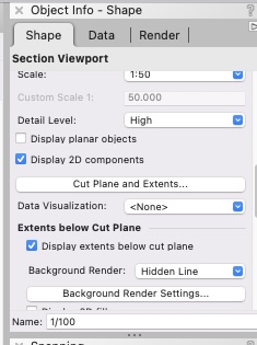
-
Coordinating representation modes in plan and section...
line-weight replied to arquitextonica's topic in General Discussion
...but beware, there is a difference between a horizontally cut "section viewport" and a "horizontal section viewport". -
"Framing member" vs "structural member" tools
line-weight replied to line-weight's topic in Architecture
Thanks for the reply. I'm waiting for SP3 to arrive before I'm able to start using 2023. Once I do, I'll see if I find the tool any more usable than it is now. -
Coordinating representation modes in plan and section...
line-weight replied to arquitextonica's topic in General Discussion
I'm finding it a bit difficult to understand what I am looking at, perhaps partly because of language difference. For example, I don't know what "volume model" means, or "surfaces and edges". If you could share the VW file you are using to produce the above, it might be easier for us to understand. -
"Framing member" vs "structural member" tools
line-weight replied to line-weight's topic in Architecture
I can see how using symbols in that way might be useful for some. However - most of the stuff I do doesn't involve huge numbers of repeating elements but does often involve awkwardly shaped roofs, where structure may be exposed and therefore I want to draw it in some detail, partly to make sure everything works technically/geometrically and partly to check what it looks like and visualise it. So drawing time is not used up by having to repeat a rafter 100 times, but it is used up drawing all sorts of special conditions where structural members meet at angles or are trimmed around window openings, that kind of thing. This is why the "structural member" tool looks appealing in theory ... I can tell it that member A meets member B at this point, give it the basic reference or setting-out geometry, and have it calculate things rather than me having to manually trim beams on the diagonal and this sort of thing. And then it's all editable parametrically and non-destructively, right? That's certainly what this video suggests And in particular look what happens from around 3:15 to applause from the audience! But it turns out when you try and use it in some kind of real world application it's hopeless, because of a bunch of limitations and mainly because - at least as far as I can see - it's virtually impossible to edit anything accurately - simply resizing the length of a beam causes horrible unpredictable behaviour and I can't even see a way of connecting two already-extant members. This perhaps explains why I can't really find any video tutorials anywhere going into any depth about using this tool in practice. That video is from 6 years ago and improvements since then seem fairly minor. This thread from last year lists just a few things that need fixing: https://forum.vectorworks.net/index.php?/topic/90654-structural-member-usability-improvements/#comment-414503 (Can @Matt Panzer tell us whether the "enhancement request" mentioned in that thread went anywhere?) So unfortunately, for me at least, for now the Structural Member tool goes back in the (overflowing) bin I last threw it in 5 years ago - the one for Vectorworks tools that would be really great if they actually worked and were actively developed, but which in practice are not usable. -
"Framing member" vs "structural member" tools
line-weight replied to line-weight's topic in Architecture
Let's hope we don't get yet another tool that partially duplicates an existing one that then gets abandoned.