line-weight
-
Posts
3,757 -
Joined
-
Last visited
Content Type
Profiles
Forums
Events
Articles
Marionette
Store
Everything posted by line-weight
-

I want to draw PVC pipes and fittings?
line-weight replied to Bruce Kieffer's topic in General Discussion
Ah yes I remember now. You've not found any solution to that, obviously. Do they seem uninterested in fixing it at the 3dconnexion end? I seem to be lucky in that I use the default mode (helicopter is what I use I think). -
I want to draw PVC pipes and fittings?
line-weight replied to Bruce Kieffer's topic in General Discussion
Looks good, but sadly at €550/year subscription cost, rather expensive for those of us who just need to do this sort of thing occasionally. -
I want to draw PVC pipes and fittings?
line-weight replied to Bruce Kieffer's topic in General Discussion
Mine still works in VW2023! -
Imagine my excitement when I read this mention of velux rooflights this morning: Well, it's true that there are now some velux rooflights in there, but they are just the "flat roof" types and not the widely used pitched roof types. They aren't parametric in any way - separate 3d symbol for each product/version. It's better than nothing. Would be great to have the full range of pitched roof ones including all of the flashing and internal reveal elements that go with them. Even if I had to manually rotate and insert them into holes cut in roof faces. If they were parametric in some extent, meaning that I could do stuff like set the pitch in the OIP, or easily flip between different sizes without replacing the object, all the better. It would save an enormous amount of design time.

-
Doors and Windows not Creating Holes in Walls
line-weight replied to Anelisa's question in Troubleshooting
The problem that people are having, is that the door/window *is* inserted correctly in the wall, and it registers as such (if you select the door/window, its OIP will say "window in wall"). And yet the hole is not being cut. In the scenario you describe, there would be a different result: if the door/window is selected it would not register as "window in wall" in its OIP. But of course you are right, it's the first thing someone having this problem could check, just to make sure.- 100 replies
-
- 1
-

-
- window tool
- door tool
- (and 1 more)
-
I'm always on the lookout for a decent application that lets me store all this (diverse forms of information) in one place. Like a sort of virtual pinboard if you like, because hopping between multiple folders (which is what I use too) can get tedious. I have found a few that are potentially ok, but end up nervous to use them because they use proprietary file formats so I get worried that I'll lose everything if the app stops being maintained, or if I want to retrieve info in the future.
-
Interesting question because I have been considering storing more "notes" type info within the VW file. Typical use case scenario for me would be for example wall or roof buildups. These tend to evolve through a project, starting off as notional and ending up as fully specified. I tend to have sets of written notes early in the process, separate from the VW file. These might list various options for a buildup along with rough U-values. Maybe some notes on specific products and where I found them/who I spoke to about them. They don't go in the drawing file because at that stage I won't necessarily have set up the sheets that will eventually contain this information for pricing/construction purposes. Then at some point, some of this information does move into the drawing file, because I start setting out those sheets, and some of the info moves into the notes database and lives in callouts on those drawing sheets. It's the intermediate stage where the information has evolved into some level of detail, but is not yet finalised or fully decided, where I'm not sure where it should live. It tends currently to exist in two places in parallel, which is not ideal, because it's easy to lose track of which is the up to date version. Especially on projects which progress in fits and starts, where I might return to things after a pause of days/weeks/months. That's a long winded way of saying I'd also be interested to hear others' workflows. My concerns would include some about making files overly large. Especially if I were to start using it as a way of storing visual references. Or, even just product datasheets in PDF form, etc.
-
Do you mean Z value? And what do you mean by "page level"? Do you mean a dwg simply with text objects noting the AOD levels or do you mean a dwg that contains some objects that already have the right AOD z values in 3d space?
-
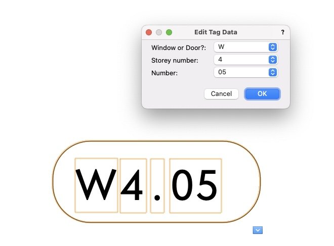
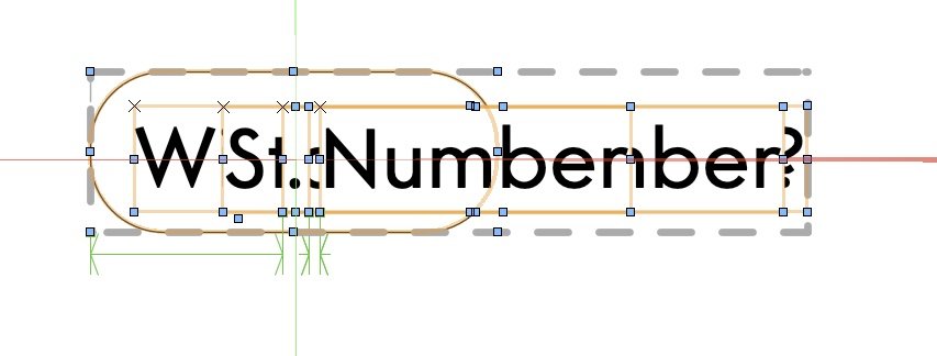
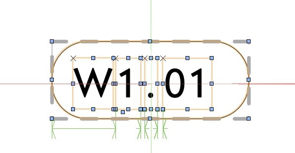
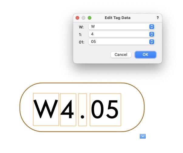
This is currently annoying me within a "data tag" layout but I think this applies to other types of object too, where there are dynamic text fields. When I am editing the layout of a data tag, each dynamic text field is displayed containing the text of the field label, rather than its default value. This makes no sense - and makes setting the layout unnecessarily awkward. Why? Because if I have a field that is designed only ever to display a single letter or number, but I want its field label to be something like "storey number", then it's the text "storey number" that gets shown in the tag layout when I'm trying to edit it, and it overlaps other elements (that it will never overlap in actual use) making everything illegible. For example, here is a data tag and the dialogue box I can use to set its contents: But if I want to edit its layout this is the mess I have to work with: To give me a layout that I can actually work with, I have to set the field labels to one of the potential values of their content, which gives me a tag layout that I can edit in a manageable way: However the dialogue box for entering data then has to look like this:
- 1 reply
-
- 2
-
-
Doors and Windows not Creating Holes in Walls
line-weight replied to Anelisa's question in Troubleshooting
You're right that you have to make sure you are placing into the wall. However this is not the problem described in this thread. The problem is that doors & windows which have been placed properly into the wall suddenly lose their hole-cuts, for unknown reasons.- 100 replies
-
- 1
-
-
- window tool
- door tool
- (and 1 more)
-
Architectural Fees - how to get more $$ upfront?
line-weight replied to Shortnort's topic in Architecture
If it's quicker for you to produce in 2D, then why not stick with doing things that way? It's perfectly possible to use VW for a purely 2D workflow. A few years ago I transitioned (within VW) from a purely 2D workflow to one where I produce a 3D model and then generate my 2D documents from this. To start with, things that I was well practiced in doing the old way, took rather longer, but as I became more familiar and comfortable with the "new" way, I found that there were many drawings I could now produce more quickly. Certainly, the process of making changes to a design, and updating multiple drawings, is now *much* quicker and less painful. -
3d fillet editability
line-weight replied to jmcewen's question in Wishlist - Feature and Content Requests
See here -
Yeah, it would be a bit worrying if all this were news to the folks at VW HQ.
-
Architectural Fees - how to get more $$ upfront?
line-weight replied to Shortnort's topic in Architecture
I know it's not a luxury everyone has, and I operate at a quite small scale, but I simply try to avoid the kind of client who says things like "don't you just push a few buttons now" or who tries to negotiate fees down, especially if the basis of their negotiation is an argument that this is how much time they think is necessary to do something. I make my judgement of how much time it's going to take. I know better than them because it's me who does it every day. I make my fee proposal. If they think it's too much, fine, they can try someone else. I'm quite aware that there are certain types of job where someone else will quote a much lower fee than me to do the "same" thing. I know they won't do the same thing though. They won't allow time for a design process that lets a client consider and reject a few options before settling on something. They will use various of the shortcuts mentioned above - standard details, template designs and so on, which probably will not in the end provide the client with the best design for their particular brief. There are certain types of jobs where my approach simply isn't necessary - and I just tell clients that - I could give you a fee quote but it'll be more than you'll be given by XYZ CAD services, and XYZ CAD services are better suited to what you want to do (quick, cheap, off the peg drawings for something very standard). I don't exactly understand the question in the OP - I don't quite get what is being asked. What's meant by "schematic and design development services" and how does it relate to BIM? And what is meant by BIM? Genuine BIM workflows to do with exchange of information with other members of the construction team, or just drawing more in 3d? -
Change the forum sign up process to stop usernames becoming thread titles
line-weight replied to line-weight's question in Forum Feedback
"Discussion topic"? -
Change the forum sign up process to stop usernames becoming thread titles
line-weight replied to line-weight's question in Forum Feedback
I think @JuanP said at the top of the thread that it was hard coded in the forum software so they can't change it. -
The model however doesn't show a true lattice - the slats don't lay on top of each other flat. At the top they do the exact opposite. And it doesn't demonstrate a geometry that you could make in real life by bending straight strips.
-
This doesn't exactly answer your question, but this strikes me as the sort of thing where you could spend hours trying to model it accurately in 3d, only to find that when you get to the "making it" stage there's some small detail that means what you've drawn can't be done, or that there's a much easier method that would produce something not quite like what you've drawn but which would be perfectly acceptable. In other words if it was me I'd consider skipping the 3d model stage - and the drawings I'd give the person who's going to make it would simply define the overall shape and dimensions, and an indication of how you'd like the lattice-work to look.
-
You might find this thread useful/interesting. https://forum.vectorworks.net/index.php?/topic/90654-structural-member-usability-improvements/ There are still lots of annoying things about the structural member tool but I have been using it a bit. For me, it's less bad than the framing member tool. (There are some scenarios where you can use a roof face object to create eg. timber rafters. Otherwise, for me it's generic solids.) Not being able to lock the pitch is indeed frustrating. However, there are a couple of ways you can change the length without affecting the pitch. Firstly you can do it manually by resizing in a 3d view (rather than a top plan view). Shift+drag on the end points. Snapping the end points to where you want them is a different matter and gets complicated when you are using offsets etc. Alternatively you can do it in the OIP. NB if you change the value for the span, the start and end Z heights stay the same and the pitch changes. However, if you change the value for the length, the pitch stays the same but the end location moves (in plan and Z height). If you get to working out how it behaves, then you can actually control structural members quite precisely, if not intuitively or conveniently. I've found that it can (maybe??) be worth using them once drawings get to a more detailed level, when you do want to be quite precise, and the likelihood of future wholescale changes is decreasing. For example in setting out complicated roofs, you can choose a Z height for the ridge, or the eaves, or whatever, using story levels if you want, and then work from here using the various controls for start/end offsets and so on. It's one of those tools that's nearly very useful, but remains at "just about usable" stage because of unfixed bugs and lack of development. That other thread lists all the things that need to change. We'll see if any of it gets implemented before we all retire or get replaced by AI.
-
Single Point Matched Curve Tutorial
line-weight replied to VIRTUALENVIRONS's topic in General Discussion
That's all fair enough. In my opinion, NURBS modelling is not very usefully implemented in VW, and it really doesn't help that there is no proper documentation. Unfortunately, examining the method you describe doesn't change my mind. To generate that particular geometry, I think it would be more efficient, more easily editable, and give a cleaner result, to use the subdivision tool. -
Single Point Matched Curve Tutorial
line-weight replied to VIRTUALENVIRONS's topic in General Discussion
And there's another problem, which is that the above isn't actually true, as far as I can see. Using the 24 locus points method does not produce an oval with the same geometry as the one produced by the oval tool. This is visible in the tutorial video. Here is a zoomed in view of the original oval (red) and the one generated with the 24 points (green). They don't match and the green one has become asymmetrical. I believe this also means that all of the versions of the oval used to create the loft are not quite the same (because of the different start/end points). This may be why the resulting solid object is ever so slightly messy. There are also some issues in controlling the exact rate of "rotation" around the path/rail because when you "rotate" by one of those 3-segment steps you are not rotating by exactly 30 degrees. And, if instead of rotating by 180 degrees, you wanted to rotate by some non-regular angle, say 87 degrees and then back again, you'd have to make the ovals using a huge number of locus points (360, I think). Doing a convert-to-nurbs on an oval does appear, as far as I can see, to produce an oval that is geometrically the same rather than an approximation.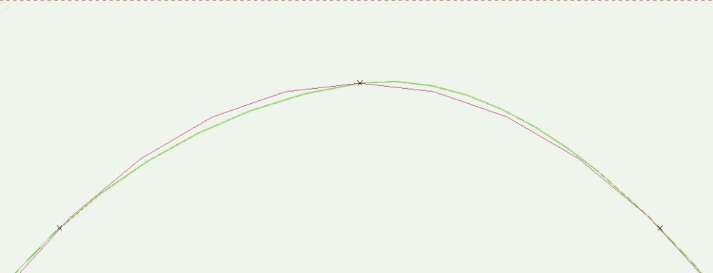
-
Single Point Matched Curve Tutorial
line-weight replied to VIRTUALENVIRONS's topic in General Discussion
The thing is, the "matched curves", more conventionally called the "profile curves" in the loft command, they don't really turn by 180 - because each curve is not the same. They have to be individually made (in a very laborious way) so that they each have a different start and end point. What happens is that the profile shape is distorted as it runs around the path, so that when it meets itself again at the "join", the two profile curves that are joined are not rotated relative to one another. Ok, so you might say this is pedantic, but the point is that it severely limits what can be achieved with this method, because it doesn't work for any profiles with sharp edges. Only curved shapes that can be smoothly transitioned between each other. That's why it doesn't work for the mobius strip. -
Single Point Matched Curve Tutorial
line-weight replied to VIRTUALENVIRONS's topic in General Discussion
right, but how is anyone coming across this thread supposed to be able to find it? Anyway, the file is here: -
Single Point Matched Curve Tutorial
line-weight replied to VIRTUALENVIRONS's topic in General Discussion
@VIRTUALENVIRONS I have a couple of requests. - Please can you try and keep discussions relating to a particular topic in one thread where possible. I think there are now 4 or 5 separate thread where you mention this basic concept, which you call "single point matched curves" and still it's unclear what is special about it. It makes it quite annoying to engage in any discussion because it abruptly comes to a halt on one thread, and the only way to find the continuation of it is to happen to come across some other thread. Plus, the work anyone puts into making any points in response gets lost. If you are having trouble re-locating threads you previously started or posted on, use the "follow topic" button whenever you contribute. - Please can you post the file itself that you show in the video, so that we can examine it for ourselves. If you are genuinely interested in us understanding what you are trying to say. The video is too short and fast for anyone to follow and replicate all the steps properly. For example, at the end where you are showing the isoparm you don't show what happens at the critical bit which is where the "seam" would be and where VW closes the curve. -
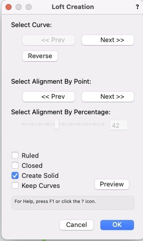
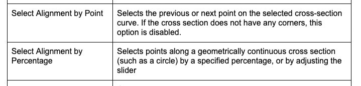
Well, I tried the same method but with rectangles (converted to nurbs curves) instead of the rounded rectangles. But I'm not offered the "select alignment by percentage" option. Why is this? It seems like it's because it has corners. It has to be a "geometrically continuous cross section". And that would appear to rule out the possibility of creating anything with true edges.