line-weight
-
Posts
3,757 -
Joined
-
Last visited
Content Type
Profiles
Forums
Events
Articles
Marionette
Store
Everything posted by line-weight
-

A way to make a variable Extrude - ¿ Use a PIO ?
line-weight replied to Elite Exhibits's topic in Solids Modeling
Hrm - I think this is my memory being unreliable. Is it in fact that the issue is that those polygons can't each be in a different class, or have a different textures applied? So therefore if you want to make a window frame with different finishes inside & out, this is when you need to make separate EAPs? If I'm right about that then in your example above, the thermal break portions of the window frame can't be rendered in a different colour/texture from the metal bits. Other examples would be where I want to make a wall-coping assembly that involves a couple of different components in different materials, say something like this: in principle the EAP tool might seem quick way of applying this all the way along a parapet top but not if the concrete coping, the copper pieces, the grout, the timber fillet all have to be rendered the same. That would apply in section too.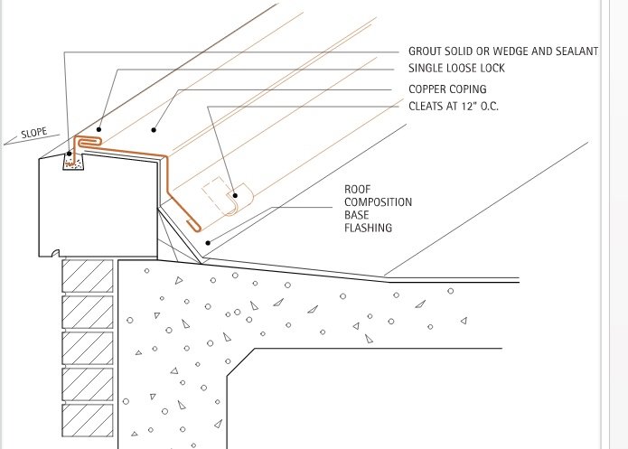
-
I know there's a hyperlink tool (which I'm yet to try using) but what I actually want to be able to do, is have a block of text, where there's a hyperlink within the text, eg I might want a note on a drawing that says: Windows to be installed following all supplier guidelines, as per www.windowsupplier.com/installation guidelines This is not possible, is that right?
-
Draw a single brick. Rectangular duplicate array, repeated 1.5 brick lengths* horizontally, 2 brick heights* vertically. Then duplicate the array that is produced, and move it 3/4 brick length horizontally and 1 brick height vertically. For this kind of thing it can feel like using symbols is the efficient/clever approach, but actually I often find it isn't - the brick itself can be a symbol but beyond that just a dumb group, of that brick arranged into a panel of the desired size. To change the panel size just means deleting or adding portions and this can be done pretty quickly. *of course, these should actually be the brick co-ordinating sizes. There will be some decisions about whether you want to want to model the mortar joints too.
-
A way to make a variable Extrude - ¿ Use a PIO ?
line-weight replied to Elite Exhibits's topic in Solids Modeling
For example... say I want to make a representation of a particular window frame. I make the path a simple rectangle, and the profile the cross section of the window frame. This is a quick way to make a rectangular window frame with a custom profile. And if i want to then make another window, same frame profile but different size/shape, then all I need to do is make a copy and edit the path to the desired size/shape. But... what if I want to make a simple casement window. There is an outer fixed frame and the inner frame that makes the opening casement and holds the glazing. It would be nice if I could simply use an EAP again, with the two frame sections in the EAP "profile" but this is not allowed - I'm only allowed one object in there. So I'm forced to do this with two EAPs, one for outer frame and one for inner frame. And if I want to make a version of this window that's a different size/shape then I have to go into each EAP and adjust the path in each individually. If the EAPs could use a symbol for the path, then I could have my two EAPs, both using that same symbol as the path, and I could simply edit the path to a different size/shape and the two EAPs would update in sync with each other. Obviously the more complex the assembly, say you want more than two extruded profiles following the same path, the more benefit of being able to do this. -
A way to make a variable Extrude - ¿ Use a PIO ?
line-weight replied to Elite Exhibits's topic in Solids Modeling
One of the frustrations of EAP is that you can't use it to extrude several profiles along the same path, without making duplicate EAPs. And then if you want to change the path...you have change it in each one. But if an EAP could use a symbol for the path... -
A way to make a variable Extrude - ¿ Use a PIO ?
line-weight replied to Elite Exhibits's topic in Solids Modeling
Structural members can pretty much do this can't they? Although I have a feeling there is some bugginess when you use custom profiles. If we could have something similar for extrude along path, that would be rather handy... -
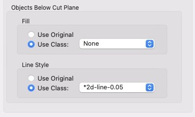
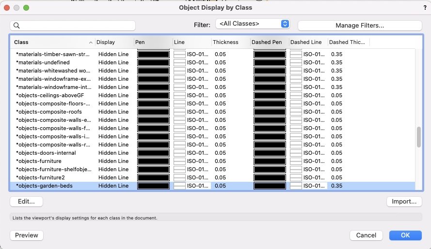
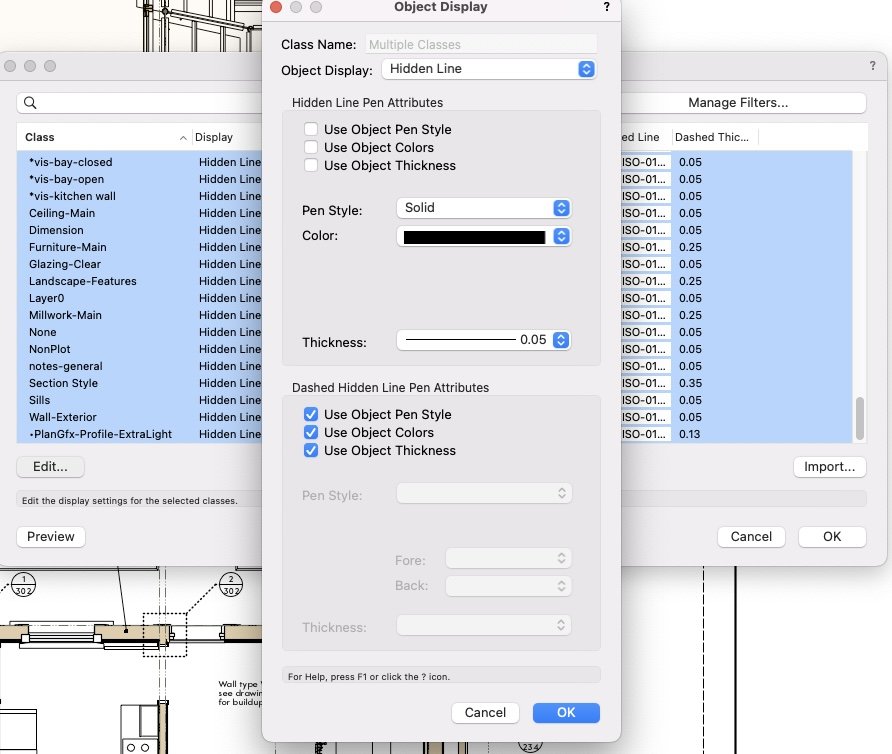
I am experimenting with this - I am a top-plan refusenik and instead use horizontal sections for my floorplans. Therefore, making a reflected ceiling plan in theory is as simple as changing the settings on a floorplan to view things above the cut plane. What's a little annoying is that doing this does not parallel how you set up a regular floorplan in a horizontal section. When you set up a horizontal section floorplan, you tick "display extents above cut plane", and then you go to the advanced properties button, and in my case I specify that everything is going to be drawn in my default elevational linework class: But the same process for a RCP is a bit different. You tick "display extents above cut plane" but then, in order to set what this is going to look like, you don't go to the advanced properties button; instead you have to use the "object display" button in the "extents above cut plane" section. What this does not then give you is a "use class" option. You are given a list of all your classes, and you have to choose how objects in each class are to be drawn in elevation in your RCP: I usually have a very large number of classes. I basically have to select all of these classes, and then specify that they all use a particular pen type, colour, etc: And tell it to use a pen type that matches my elevational linework class. This, basically, works, but seems inconsistent and I think it should be possible to set up in exactly the same way as a "normal" horizontal section, that is specify that none of it is drawn by object but all of it is drawn in linework using a chosen class. Then, if I make an adjustment to my elevational linework class, it'll update in RCPs as well as all my floorplans, elevations etc. Also, I'm yet to see what happens when I make a new class - will I have to go and manually adjust that specific class to be drawn with the right pen in each of my RCPs?
-
The fact that I'm given these various curved options for the path, suggests that it is not working as designed. That, or it's an example of truly terrible interface design, giving people options to choose modes that don't actually work. It also gives me these options in the OIP: And I don't see anything in the documentation that specifies the path object can't be curved: https://app-help.vectorworks.net/2023/eng/VW2023_Guide/Shapes2/Chain_extrude_properties.htm#h


-
I too have never used it (nor really noticed it). Had a quick go out of curiosity. Can get it to sort of work, but the first thing I notice is that if I draw a curved path, it doesn't follow it - it follows something like a segmented straight path between the nodes I've used to define eg a bezier curve. My instinct: this is one of those broken VW tools that got introduced, then never maintained. And is left there, to waste people's time in working out how to use it, only to find it doesn't work. So I did a google, and indeed this bug was noticed and reported back in 2010. But seemingly has never been fixed: Thirteen years ago.
-
You need to tell us more about what exactly you are printing and how. For example are you printing from a sheet layer with the linework in a viewport with a given scale? Or are you printing from the design layer? Are your dimensions/text on the design layer or in viewport annotations? Are you exporting as PDF before printing, and so on?
-
Cutting Complex Patterns Into Solids
line-weight replied to Chame_liam's topic in General Discussion
I would consider building these as individual flat faces, then assembled into the hexagonal columns. Why? because it might help keep a handle on how what looks like a continuous pattern wraps around the 5 or 6 faces. I would lay out the 6 faces alongside each other, as if the column wall had been unfolded. I'd put the laser-cut pattern behind this "unfolded" set, in a different class or layer. This would let me check that the pattern runs between the faces exactly as I want. I'd make each face as a simple extrude and then subtract the pattern from it. This might involve copy-and-paste-in-place-ing and slicing up the pattern, to make the necessary pieces, but the reference pattern could remain in the background, as a check that things weren't getting displaced. So I'd end up with the 6 faces, each with the pattern cut out of them, lying side by side. Then I'd make each face into a symbol and assemble the finished columns out of symbol instances, each face moved and rotated into its rightful place. Any further edits to the pattern, I'd not need to touch the assembled columns, I would do all of the editing in the original symbol instances, which would still be clearly laid out next to each other. All of this might need a bit of careful duplicating, and moving things in and out of the original symbol instances, but as long as they don't move in space, this can usually be achieved by using the paste-in-place command. It it's usually possible for example to replace one of the subtracting objects, within a subtraction solid, without having to re-perform the subtraction operation. As mentioned above, the more layers of subtraction/addition you have, the more you make your life difficult, but if you can keep a handle on things, I find this kind of method can be quite efficient. (For example... if you want to subtract objects B-Z from object A, there are a few different ways of doing this, and some make certain changes easier: - (((((A-B)-C)-D)-E)....-Z) done by subtracting B from A, then C from the resultant solid, etc - normally a very bad way to go - A-(objects B,C,D,E....Z) done by multiple-selecting everything and choosing A as the object to be subtracted from - A-(addition object of B+C+D+E...Z) done by adding B-Z then subtracting that from A. The two last methods produce subtly different means of making subsequent changes, and I find the latter can be an easier way of keeping a handle on things. Whether it would be worth using this kind of approach probably depends on the likelihood of the pattern getting changed in the future, and how precise the drawings need to be. Also, I might start out happily with the above plan and then at some point realise something wasn't going to work, due to the peculiarities of how VW behaves with symbols and solid subtractions. -
In this forum, the enthusiasm/time put into suggestions for solutions is often much greater than the effort made by the OP in clearly explaining what it is exactly they want to do...
-
This is a rather inconvenient and convoluted method though. Especially if you are dealing with a curved wall. We shouldn't really have to resort to this.
-
Your video doesn't seem to have uploaded. The wall reshape tool sort of works for me, but there are a number of things about it that are a bit janky, for example, what you are given as a preview of what's going to happen when you modify it, plus adding additional nodes, which doesn't let let you add them in the middle of a wall section, you have to kind of duplicate an existing node vertically and then move it horizontally. Screen Recording 2023-08-14 at 14.03.33.mov
-
Perhaps we just have to accept that we are stuck using software that has a rather limited and niche market (3d modelling aimed specifically at building construction), and therefore Vectorworks *and* any alternatives just aren't going to see major improvements any time soon. Nor are we likely to see meaningful competition from new players that might shake some of the established software companies out of their complacency. My impression is that with nearly all the things that could be improved about Vectorworks; the obstacles aren't fundamental technical ones, they are to do with the amount of resources that those in charge are willing to put towards them. This is why, whenever I am moaning about Vectorworks, I try to make clear that my frustrations aren't directed at the employees who presumably work hard trying to improve things, they are directed at the management level who decide not to resource development, which I think is why progress goes at such a deathly slow pace. Also ... Vectorworks, as a 2D drawing package is actually fairly mature. Most of the big issues are to do with using it fully for 3d modelling and using the 3d model to produce the working drawings. Many of us active on these forums are trying to use it in that way - but I wonder whether in reality, we represent a minority of users. Practices in the construction industry are notoriously slow to change, and I suspect that there's a large portion of the user base who still just use it in 2d, therefore reducing further the incentive for its 3d/BIM capabilities to be developed quickly. I have little recent experience with other 3d modelling packages, aimed at the mechanical engineering or more general sectors, but from what I see of them, it appears that they are miles ahead of VW as far as their basic modelling logic and interfaces are concerned. Some like Blender aren't even paid for. Watching youtube videos of people modelling in these programs, to me, makes the VW interface look especially old fashioned and clunky. Maybe it's partly that producing something optimised for building design is especially difficult (I can see plausible reasons for this being the case) but it must also be to do with the sizes of the potential markets. The number of people using something like Blender must dwarf the number of Vectorworks users trying to do proper 3d modelling.
-
I think i get that bit, it's how you then fold it - do you group-select a bunch of faces and do some kind of rotate action around the edge that's on the inside of the fold....but then what happens to the edge on the outside of the fold?
-
Do you mean you can use it to take a flat thing with a thickness, and then make a fold in it? How do you go about that?
-
yeah, I am also not too sure, and i think it's the case that you have to select all the faces individually, a bit like I have done in the screen recording above ^^ and then you get messy edges along the top and bottom. It can all be fixed of course, but could be tedious on large objects. If I was modelling something that would be made from, for example, welded-together 10mm thick steel plates, then I might be tempted just not to thicken the model, leave it as flat planes and represent it in section drawings using a thick line. If it had to be made up from a skinned timber-frame, though, then I would need a different strategy. Might even think about using "roof face" objects, much as I hate them.
-
How would you do this step though?
-
You are right that this is not entirely straightforward in Vectorworks, if you want something that's a series of connected flat planes at different angles that have a thickness. The best way probably depends a bit on how they are going to be made (because that determines things like, how thick are they, are the edges at right angles to the faces, how are they connected and how much detail do the drawings actually need to show). Also, it depends on how much you want to adjust and tweak before finalising. I would tend to draw them as a series of 3d polygons to start with. Draw the first one, then draw the next one so one of its edges exactly matches one of the first one's edges, and so on. So you end up with a sort of psuedo-mesh. Vectorworks (as far as I know) doesn't really do true meshes, where you can move a vertex and pull all of the adjacent faces. Hence why I call it a pseudo mesh - you can tweak it about a lot but you have to adjust each polygon individually. It's converting it to a series of faces with thicknesses that is the point where it then becomes somewhat frozen, because it's then very difficult to go back to the original mesh geometry to change anything. Giving the faces a thickness can be done with the shell tool, but you might not like the way it deals with some of the edge-junctions. Or you might not be too fussy. There may be some method that involves converting to a subdivision object, giving you a bit more control over subsequent edits. I am not really a subdivision expert. Useful to know is that you can perform an "add solids" operation on multiple connected 3d polygons, and it will join them together into a single object, meaning that operations like offsets or shell have different & possibly preferable results compared to what would happen if they are left as individual polygons. It might be that it's something best to model in another application and then import the geometry to VW, if it's the case that the other application lets you do more non-destructive editing on the geometry. Screen Recording 2023-08-01 at 16.07.05.mov
-
My question would be, is there any good reason for them to be separate object types. Seems rather like making external walls & internal walls separate object types.
-
I find the connect/combine tool on pitched roofs to be very unreliable. Sometimes it does what you want and sometimes it does something else and sometimes it does nothing at all. When it becomes troublesome, I find it can help to pull the two edges back from the expected intersection line, then try again. Also, make sure that the two edges you're trying to make connect are both continuous straight edges (and don't have extra nodes hidden in them). Roof faces are one of those "barely usable" objects. They are useful sometimes, but very limited. I sometimes use them at earlier design stages but they very often get swapped out for directly modelled solids once I am doing details. Apart from the unreliable connecting behaviour, there is a lack of control over what happens at edges and at holes. It's a shame because with a bit of attention they could become very useful and a massive time-saver. I'll not be surprised if this doesn't happen for years though. Also I'm not sure why slabs and roof faces have to be different object types. Standard Vectorworks nonsense - multiple half-baked tools that do nearly the same thing.
-
You can try doing "convert to group" in the modify menu but I think you are likely not to get quite what you want. Can't now remember the details, but at least when I last recall this being discussed, there is no clean way just to convert a viewport to 2D geometry, frustratingly. Things may have changed though.
-
I want to draw PVC pipes and fittings?
line-weight replied to Bruce Kieffer's topic in General Discussion
I see they have something similar to the 3dconnexion devices pre-order only & "shipping April 2024" so is that connected to 3dconnexion's patent running out, mentioned somewhere? Certainly it makes me feel quite nervous, being highly dependent on the 3dconnexion device, but them seemingly uncommitted to continuing to support mac/vectorworks users. Some competing devices would be welcome.