


line-weight
-
Posts
3,793 -
Joined
-
Last visited
Content Type
Profiles
Forums
Events
Articles
Marionette
Store
Everything posted by line-weight
-

"Howdens" (UK kitchens) base cabinets have wrong dimensions
line-weight replied to line-weight's question in Troubleshooting
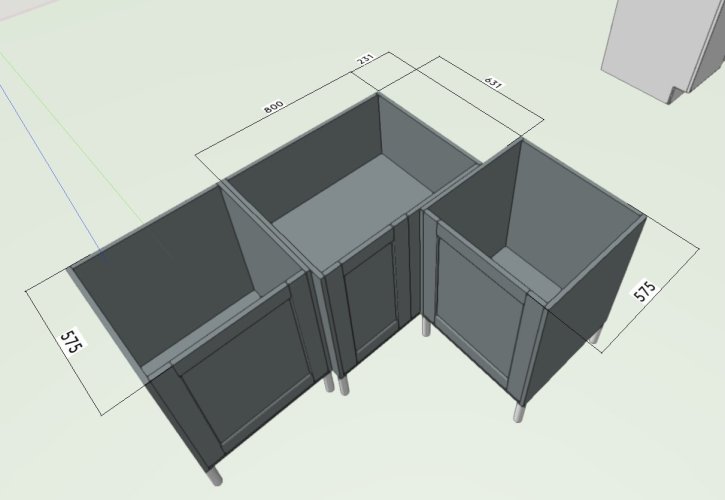
Hi @Andre L - ok, firstly I see, yes there is a set using the new cabinet tool, which show up as "Shaker" style in the resource browser whereas the old ones are called "Universal" and I think are in a legacy library location. However - if I use that "Howdens Shaker Base Cabinet style", which is built with the new cabinet tool, those corner units, the ones discussed earlier in the thread, are still not right. This becomes clear if you try to assemble them together with two other units to make a corner, even with the 231mm set-off distance. The corner units should match the 575mm front-to-back depth of the regular units. The corner unit in this screenshot is "model no 800R". That the cabinet is 631mm deep instead of 575mm is the same error I highlighted near the start of the thread, although I certainly see this is all quite confusing (and I confused it more by not understanding the model numbering) and the way Howdens label things is not all that helpful. But if you look at @Tom W.'s post above it shows how these corner units are supposed to go together. Note the little L-shaped projecting piece that forms the actual corner. I think 631mm is probably giving the dimension to the nose of this. By the way, the cabinet legs also need to be set back from the front, otherwise it would not be able to install a kickplate flush with or set back from the cabinet fronts.
-
"Howdens" (UK kitchens) base cabinets have wrong dimensions
line-weight replied to line-weight's question in Troubleshooting
Sorry to be annoying but I don't think these cabinet types have been removed from the catalogue. I was checking having installed VW2024 SP0 (wondering if a nice new and correct set might now be offered, based on the improved cabinet tool, but I don't think it is). -
dp
-
The first two things I wanted to see if the new cabinet tool could draw: (this is based on how kitchen cabinets are usually made/installed in the UK) 1) The base sitting on legs (sides of cabinet don't go down to floor) - Yes it can (good, although I'd like the option of drawing the legs but omitting the kickplate) 2) Services void at rear (the back panel is inset, so there's a void space between back of cabinet and wall) - I don't think it can, but happy to be corrected. The type of service void I mean is illustrated here: https://www.lemonsqueezykb.co.uk/our-cabinets.html Why does it matter? Because there might well be stuff like pipework running in there, and I might want to show this on a section. If I can take a section through a kitchen made with standard units and this void can be shown automatically without custom modelling or fiddling in annotations, that saves me some work. Additionally, showing the cabinets as the actually are, avoids any confusion when putting dimensions on a drawing. If I want a cabinet set out a bit, for example, I want to be clear whether I am giving the dimension to the back edge of the cabinet walls, or to the back panel of the cabinet.
-
Yes. Remember design layers don't really have a scale - it's confusing the way VW talks about them having a scale. When VW talks about the scale of a design layer it's more to do with a preview of how certain things (that only exist in the context of a sheet layer) look. Such as paper size or line thickness.
-
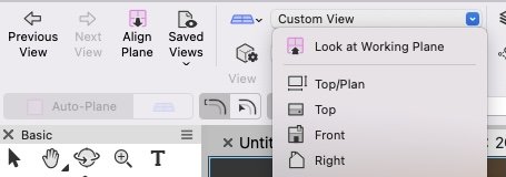
It's been moved into this dropdown, which perhaps has some logic to it.
-
Have you done the experiment of hiding all the trees, and seeing if this helps? Best to be sure about the cause of the issue before working out solutions.
-
Depth of field is interesting to try a little bit. I think it might be useful for quick presentation images where you want to (literally) focus on something particular without getting distracted by things in the background that are not fully drawn yet. I would say you can tell it's kind of "faked" but nonetheless a useful addition. It would be nice to somehow have a slider (rather than typing numerical values) to adjust the focal depth in real time.
- 5 replies
-
- 1
-

-
- vectorworks 2024
- shaded
- (and 1 more)
-
What @vassen is trying to do here shouldn't be a problem in VW, and exporting to cinema 4D is unlikely to be a useful workflow. It's not a rendering - it's a shaded view.
-
Isn't VW shaded mode clever enough to know it doesn't need to render every leaf at that scale though? Does it work differently in viewports from how it works in live views of design layers, where you can move around models with complex geometry in real time and it doesn't try to resolve stuff in the distance?
-
A one-liner View Bar in VW2024?
line-weight replied to Kaare Baekgaard's question in Wishlist - Feature and Content Requests
My first impression was also that I have lost some drawing space - but in compact mode, it basically takes up the same amount of space as in VW2023 and seems OK to me. It might be nice to be able to condense it further to one line though. I've tried the Autohide option and it works OK for me - it doesn't trigger unless I go above the "bottom" line and into the space that's the application window header (ie with test.vwx written on it in your screenshot). However, it may be that some real-life use reveals that inadvertent triggers are more of a problem than it first appears. -
Saves me making a custom icon to distinguish it from previous versions! Until next year at least.
-
Another thing... If I set up my own customised Renderworks style I can choose "apply lighting options" for this style. And let's say I choose, under Indirect Lighting, 16 bounces. I'll expect those settings to apply to any Viewport that uses that Renderworks style. Then I can make a Viewport style, where I set "Renderworks style" to be "by style" and I can choose the customised Renderworks style I've just made. But it seems that, within the settings for this Viewport style I can still press the "lighting options" button, and choose, under Indirect Lighting, say, 4 bounces. So what then applies to Viewports that use that Viewport style? Is it the 16 bounces I've specified in the Renderworks style or is it the 4 bounces I've specified in the Viewport style?
- 41 replies
-
- 1
-
-
- vectorworks 2024
- viewport styles
- (and 1 more)
-
Have just been looking at VW2024. The Viewport Style dialogue box does look promising. One thing I note though; the opportunity does not seem to have been taken to fix the confusing "Lighting Options" button in the OIP for a renderworks viewport. This is the button that (if you are dealing with a renderworks viewport) actually takes you to a dialogue called "Edit Renderworks Style" which, if you are not paying attention, can lead you to make changes to a renderworks style that applies multiple renderings and not just the one in the viewport. I have been complaining about this for years. I think this is also going to cause confusion when dealing with Viewport Styles for Renderworks viewports. Because in the settings for that Viewport Style I can choose "Lighting Options" to be "by style". And yet, a viewport with that style will have its "Lighting Options" button ungreyed. Because actually that button shouldn't be called "Lighting Options" it should be called "Edit Renderworks Style" or arguably not there at all. [edit] Oh, actually it adds a further inconsistency. If I have a styled viewport, where I have "Lighting Options" by style, then that button is not greyed out but when I press it, it takes me to a "lighting options" dialogue with everything greyed out (why not just grey out the button?) So this means that for a styled Renderworks viewport, this button does something different from what it does for an unstyled Renderworks viewport.
- 41 replies
-
- 1
-
-
- vectorworks 2024
- viewport styles
- (and 1 more)
-
Vectorworks 2024 Seems To Be Live Now......
line-weight replied to Kevin McAllister's topic in General Discussion
So does this mean that Materials can now be used everywhere - or are there still some hold-out object types? -
Yes I too try and have mostly the same classes across all projects files. Although, this always feels like a moving target, because files can remain in use through several versions of VW and my system continually evolves somewhat, partly as a result of changes in VW itself. For example, VW2024 might be the one where I start trying to use VW "materials" and if I do, then part of my classing strategy may become redundant. If Viewport Styles do include control of class visibility that'll certainly be a strong incentive to further standardise/rationalise my class naming though.
- 41 replies
-
- 1
-
-
- vectorworks 2024
- viewport styles
- (and 1 more)
-
Yes I see, you are right of course. I guess I have not previously paid a lot of attention to what happens when I bring in a style resource to a different file - whether classes that are part of it (but not present in the destination file) get imported or default to something - and whether the behaviour is consistent between different types of styles. I just tried importing a structural member style to an empty file, and I see that the class that is attributed to the SM comes in with it and is added to the classes already in the file. But a set of (possibly hundreds of) class visibilities/over-rides for a viewport style - that's slightly different because it's not objects in the classes themselves you'd be bringing in but a set of rules about how they appear, which is all rather more complicated to co-ordinate. For example if it has a rule about a particular class, which isn't in the drawing that I am bringing it into... then does that rule just disappear or does it get remembered if I later add that class to the drawing? But we will find out in due course.
-
Well that seems like a reasonable amount of RAM. Reason I asked was that I've had experience of viewport rendering (when the viewports contain a large amount of geometry) taking a very long time when RAM usage gets overwhelmed. On a mac you can monitor what's happening with memory, assume similar is possible on a PC.
-
How is your computer for RAM?
-
I guess we have to wait and see! There are quite a lot of settings for section viewports, things like how the cut plane is dealt with for example, that are outside of what render styles can control. Being able to control that stuff by viewport style would be very useful, but as you imply, class visibilities & over-rides are an important part of getting viewports to show what you want, and are also some of the most tedious things to keep a handle on. So whether or not they are included in what viewport styles can do will determine whether or not it's really a game-changer.
- 41 replies
-
- 1
-
-
- vectorworks 2024
- viewport styles
- (and 1 more)
-
I seem to be able to find snap points on such an object. Have you checked your snap settings? Screen Recording 2023-09-11 at 14.00.36.mov
-
See here
-
Ah I see. Yes I'm familiar with this problem - it's a pain. When you change the length of a defining section line it causes shifts in the location of the model relative to the viewport in sheet layers. The only way around it is to stop the section line that defines the viewport from being a "defining" one. You have to convert it to a dumb(er) object that is not linked to the resultant viewport any more.
-
But I have a feeling that sometimes the resulting polygons are not what you want. Maybe when converting mesh type objects, something like that?
-

