line-weight
-
Posts
3,757 -
Joined
-
Last visited
Content Type
Profiles
Forums
Events
Articles
Marionette
Store
Everything posted by line-weight
-

Dimensions and Notes - in Design Layer or Sheet Layer Annotations
line-weight replied to ChanLS's topic in General Discussion
Putting dimensions on the design layer also makes less and less sense the more you start drawing in 3d. -
Dimensions and Notes - in Design Layer or Sheet Layer Annotations
line-weight replied to ChanLS's topic in General Discussion
Just my opinion really (and in an architectural drawing context) but dimensions should almost always be in annotations on the sheet layer. In an efficient set of drawings, the same dimension shouldn't need to be repeated on several sheets. If you need to communicate a dimension, then it should be communicated in the right place. If it's a setting-out dimension then it should be on the GAs or on a dedicated setting-out drawing. If it's a detail dimension it should be on the relevant detail drawing. I often see drawings made cluttered and confusing by dimensions that don't need to be there, because they are already stated somewhere else. My approach of almost never having them on a design layer seems to run contrary to various VW tutorials though. I don't know if that's because my dimensioning philosophy is not a widespread one, or if it's because the designers of VW don't understand enough about how architectural drawings are put together in real life practice. -
2020 Teaser Tuesday - VGM Level of Detail - Vectorworks 2020
line-weight replied to JuanP's topic in News You Need
Sure. But my point is that if setting to "high quality" results in VW drawing in more detail than necessary, then that is somewhat independent of how much users know. Even a user with a high awareness of their computer's power and the conditions in their file would reasonably expect that setting something to a "higher" quality would provide some kind of advantage in exchange for slower zooming, etc. The way I see it, the way in which "how much users know" would affect things, is by users knowing "VW doesn't work properly therefore I have to change a setting to compensate" which indicates bad software design. But this new capability (hopefully) is an example of better design. -
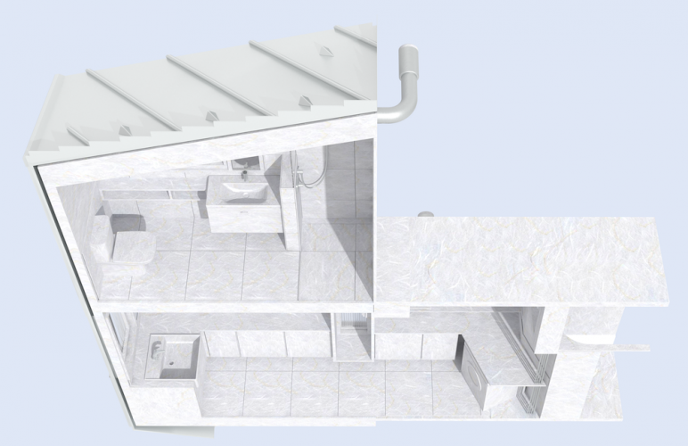
Sorry, maybe I should have made clearer, I am talking about 3d perspective, cutaway, rendered sections, not orthographic ones. For example like this:
- 160 replies
-
- 2
-

-

-
- vray
- twinmotion
- (and 2 more)
-
Are any of these 3rd party rendering things any good for creating sectional views? There are lots of things I like about RW - the single file (potentially), and all the things you can do using multiple viewports, class overrides and so on. I also feel that the quality of the renders out of RW can be pretty good - if you put quite a lot of time in. The slowness of working in RW is one of its main downfalls, but another is the fact that it really can't do rendered sectional views properly. Either I end up using design layer viewports which are truly horrible - unstable and unwieldy - or I end up making a 'manual' section where I literally cut away a part of the model, which is time consuming, and loses the 'single up to date file' concept. And either way, it can't cut things that are supposed to be solid, so they look solid (everything is hollow with paper thin faces). So I end up constructing section planes manually (something I really shouldn't have to do). So does anyone have a successful workflow for rendered, 3d cutaway sectional views? Is it worth me trying out Twinmotion, etc?
-
2020 Teaser Tuesday - VGM Level of Detail - Vectorworks 2020
line-weight replied to JuanP's topic in News You Need
Have you been given a test version to try out? -
2020 Teaser Tuesday - VGM Level of Detail - Vectorworks 2020
line-weight replied to JuanP's topic in News You Need
Bit odd the way this is explained in the video, as if it's resolving a fault in users rather than in the software. If setting the quality to 'very high' means that VW draws stuff in the distance in more detail than is necessary then that doesn't mean that users are making a 'wrong' choice, it means that VW is doing it wrong. Anyway, I wonder if this change will have any effect on the massive slow-down seen in models with imported, complex mesh objects. That includes in my experience problems selecting things (beach ball of death) when there's a complex object behind them (even if that object is not in direct line of sight view). -
Exporting to pdf - vs. image file - file size
line-weight replied to halfcoupler's topic in General Discussion
Should be fairly straightforward surely: you never throw away the data in the source document (ie the VW file) unless the user actively wants to, and you never export to a PDF document data that is outside a crop, because otherwise why would you be using a crop boundary. -
Exporting to pdf - vs. image file - file size
line-weight replied to halfcoupler's topic in General Discussion
Seeing as VW2020 is all about improving user workflow, I look forward to an improved PDF exporter that doesn't export vast amounts of data that isn't visible or necessary in the document you are exporting. -
Laser Measuring As-built (auto import to .vwx)
line-weight replied to DesireeRoss's topic in General Discussion
But what kind of accuracy are we talking about - +/-10mm or +/-100mm or worse? And does it give you proper solids or do you import into VW and it's a horrible mesh that doesn't section properly? -
Laser Measuring As-built (auto import to .vwx)
line-weight replied to DesireeRoss's topic in General Discussion
Does that really work? As in, will it make something detailed/accurate enough that it can eventually be used as the source for construction information? -
Thanks for this - I didn't know this was possible and is very useful. Just tried it - I think all you need to do is 'convert to group', you don't necessarily need to copy that group to another layer (or maybe you just mean you need to copy it to a design layer if you want to work on it at scale).
-
There's basically not any way (as far as I know) to convert a 3d view into usable 2d linework. I don't know why this seemingly simple thing is impossible. It's very frustrating. If it were possible, it would massively improve the speed and quality of early-stage presentation drawings. Build a near-enough-right 3d model, generate your views, then convert to linework and do the necessary tidying-up and add in a bit of manual 2d drawing.
-
Good Renderworks settings for "architectural model" look?
line-weight replied to line-weight's topic in Rendering
And here's another one from a different project, from a little while ago....
- 41 replies
-
- 19
-
-
-
Good Renderworks settings for "architectural model" look?
line-weight replied to line-weight's topic in Rendering
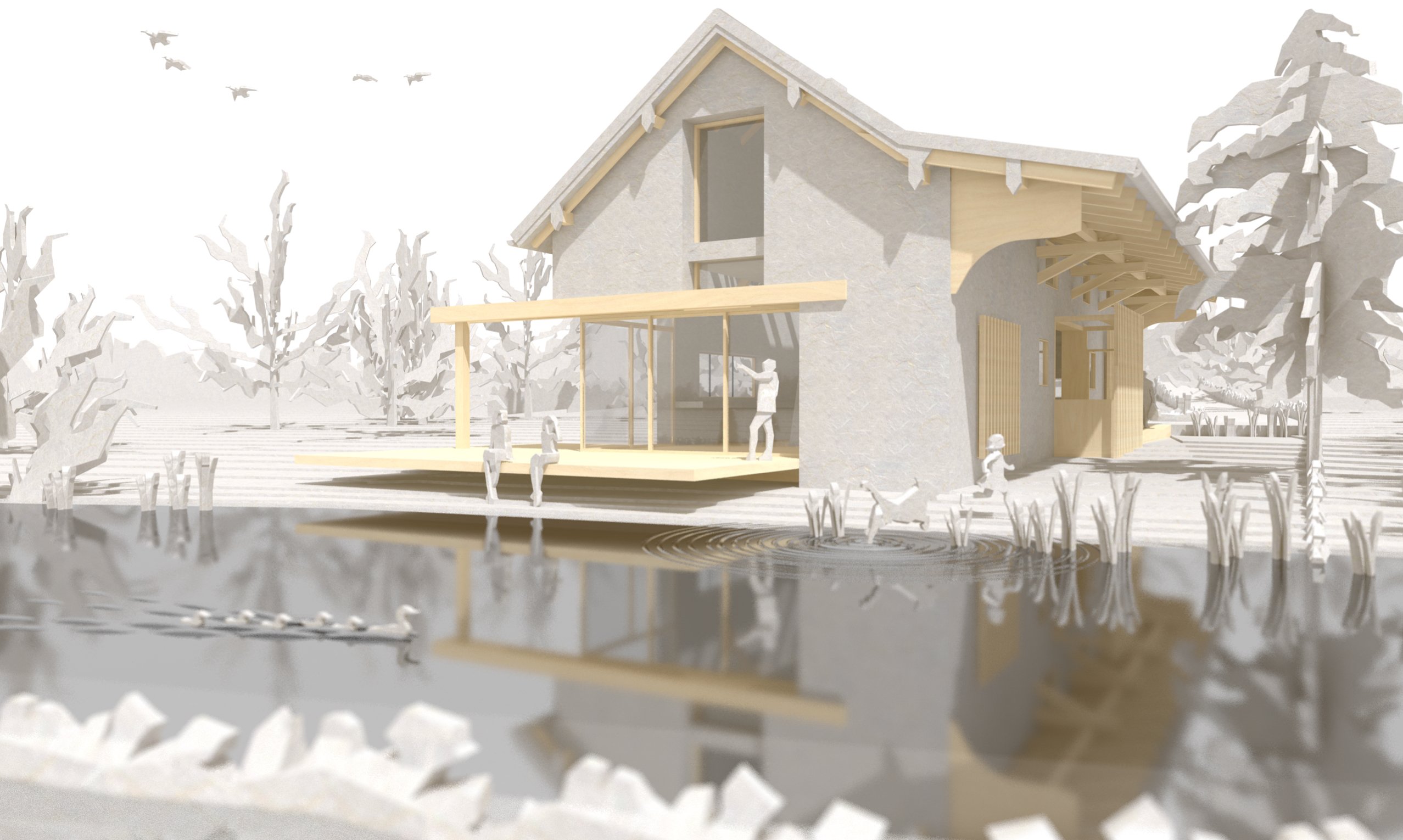
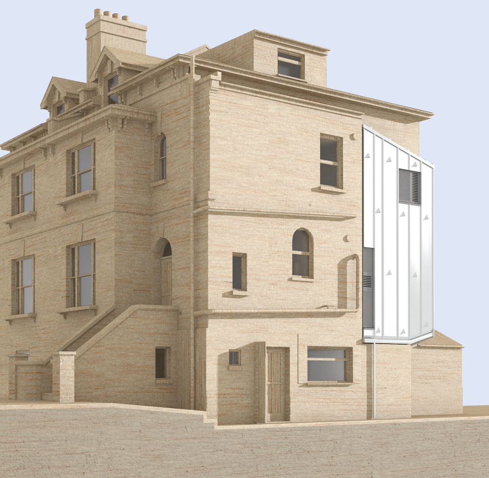
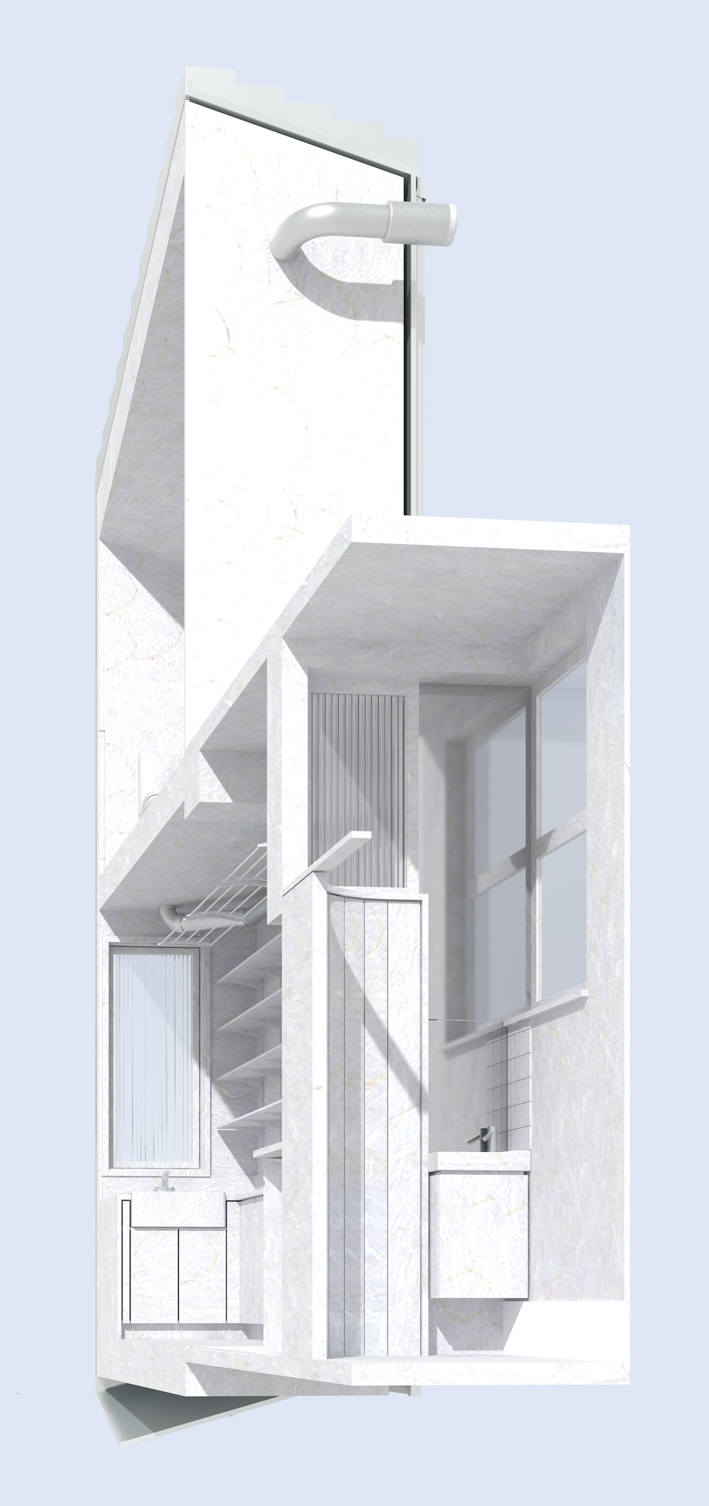
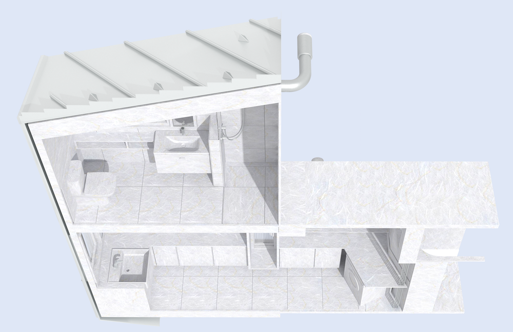
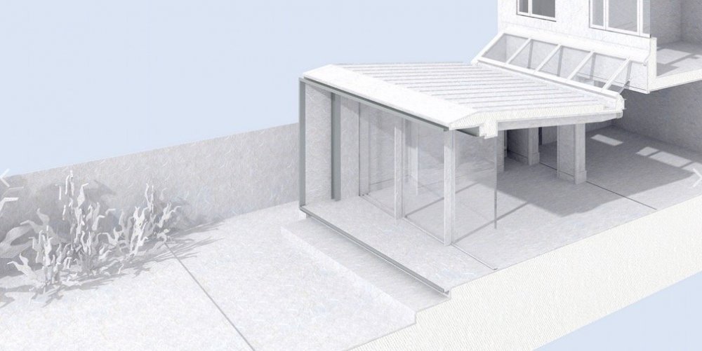
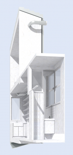
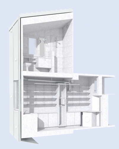
Here are some more renderings I've been doing, on the 'architectural model' theme. As ever, the challenge with the white-card ones was to get the balance of shadow and illumination right, and this took quite a bit of fiddling around. The ones with the 'balsa wood' house - I wanted the balsa wood to look not too sharp and perfect, and played around quite a lot with displacement maps to try and achieve this, but it was pretty difficult, with problems emerging at corners and the joins between wall objects. NB with the sectional ones: VW currently has no way of creating a tidy, solid section plane in renderworks. These therefore had to have a fair bit of manual manipulation. The 'cut plane' is modelled with a thin solid object, not generated automatically. These were made from the same model that I've used to produce the construction drawings for this project - but I had to fork off a version of it to make the renderings from, because it needed a few 'interventions' that would have messed up the main drawings.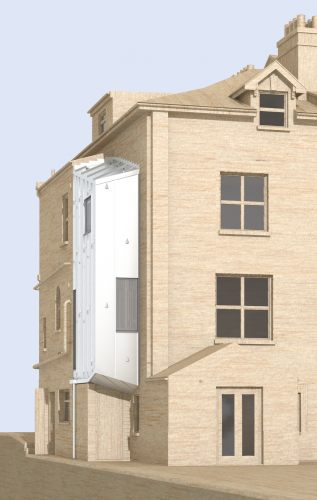

-
If you have eg. an object which is a solid subtraction (look what it's called in the Object Info Pallette) then double-clicking on it will take you to a view where you can see the objects it's built from (ie the objects that were subtracted from each other). Likewise, each of those objects might be an addition, subtraction, etc. and double-clicking on either of them will do the same .... and so on back into history.
-
Corner Door
line-weight replied to KIT KOLLMEYER's question in Wishlist - Feature and Content Requests
Had to build one of these from scratch myself recently. And then changing its dimensions is a right pain. Add this to the long list of requests for improvements to the window/door tools that has been growing for several years now. -
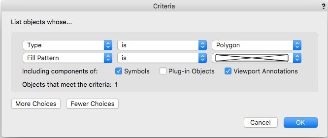
Yes, that the "none" is an option under 'fill pattern' rather than 'fill' is confusing and a classic case of VW inconsistency. (No doubt there is a 'reason' it's like this, but it is confusing from a user point of view)
-
2020 Teaser Tuesday - List Browser Direct Editing - Vectorworks 2020
line-weight replied to JuanP's topic in News You Need
yes i expect that's what it is, given that various elements extend beyond the tops of the walls. In reality just removing the floors seldom results in something as tidy as that though... external walls will tend to run to a different level compared to internal ones, and so on. -
Does this not work for you? Is the issue that this still picks up polygons whose fill is by class, and where the class fill is 'none'? Can you get around it by excluding certain classes?
-
Ah - I see, it's an American vs UK English translation issue!
-
2020 Teaser Tuesday - List Browser Direct Editing - Vectorworks 2020
line-weight replied to JuanP's topic in News You Need
Not just the toolbar but that sectional 3d model too: it shows something that is not possible right now which is a rendered sectional view that shows a solid section plane through walls etc - rather than hollow things made out of paper. I suspect it's just marketing images though, based on previous form. -
SP4 - Unstable when exiting from a viewport back to sheet view
line-weight replied to Aristocrates's question in Troubleshooting
@Aristocrates this doesn't help you in the slightest but I never, before reading this thread, realised that it was possible to go directly from annotations edit mode to design layer mode and back. I've always exited out of annotations then gone back in again to the design layer (which is a pain). So, you have at least saved me some time in the future... -
I've just been using this too - thank you very much @herbieherb Like @Andy Broomell I'd like to be able to export out-of-date viewports, so I have also disabled lines 28 and 29 (using a £ sign didn't work for me, but just deleting them did) One comment, if you run the script, but then click 'cancel' instead of 'open' in the dialogue asking you for the file location, the image is not exported (as expected) however a message saying an image has been exported is returned nonetheless.
-
Displacement mapping causes corners to 'peel away'
line-weight replied to line-weight's topic in Rendering
Yeah, I'd like the silhouette to change so that edges aren't dead straight. In the end I solved the joints between wall sections by extracting the surfaces of all wall sections, extruding them by 5mm and adding them all together as a solid. That kind of works but is not really ideal.