


line-weight
-
Posts
3,755 -
Joined
-
Last visited
6 Followers


.thumb.jpeg.48a6fdc44e48c98b8e1b507e86e57e95.jpeg)
Recent Profile Visitors
13,255 profile views


-

Multi-storey building all in one storey - would this work?
line-weight replied to line-weight's topic in Architecture
I'd say I just add levels to the storey - layers don't come into it really. My levels and layers are independent of each other, other than that the layers have to be associated with the storey in order to have access to the levels. However I'm aware that I'm not exactly using it as intended because I am ignoring most of the functionality that is to do with having multiple storeys and level types that occur in several of them. I don't quite understand how a Level is associated with a Layer (via that "Create Layer" check box you mention) or what exactly that means. I may have managed to understand it when I first figured it all out. At the moment though I don't need to understand it because my system works fine for me for now. I'm not surprised that many people don't use Storeys at all. The whole setup is very confusing. The way the various interfaces are designed doesn't help. I think in the explanation of how it works, there needs to be some kind of graphical representation of how everything (that is, layers, storeys, levels, level types, layerless levels, etc etc) relates to everything else. -
Normally when I duplicate them, the data gets updated. Today this did not seem to be happening, and I assumed it was because I'd made them not active (because ticking the box fixed it). But maybe it is unrelated.
-
Have come across a small issue. My drawing register is set up, as per @Nikolay Zhelyazkov's suggestion above, so that only title blocks where I've ticked "activate title block" are included in the register. That's fine - I can have various drawing sheets that are works-in-progress and choose not to have them included in the register until they are actually ready to be issued. However, if I duplicate an existing sheet layer, which has that box unticked, then the new sheet layer is given a new sheet number, but that number is not reflected in its title block. So for example I have sheet number 250, and duplicate it, and VW automatically numbers the duplicated version 251 (which is what I want) but sheet 251's title block still has 250 as its sheet number. I have to tick and then untick the "activate title block" box in order to get it to display the correct number. Is this intended behaviour?
-
Multi-storey building all in one storey - would this work?
line-weight replied to line-weight's topic in Architecture
Ah right. Yes, this is bringing back memories of things that I found very confusing when I was first trying them out, but I can't now remember exactly the details. Is it something to do with the difference between a "level" and a "level type"? Because in my setup I think I only use "level types" and disregard what happens to levels that are intended to repeat in multiple stories. I think I must have "layerless levels" but where is it that you make the choice between a layerless level and a story level? If it's any help, below are the instructions I wrote myself a few years back for setting up new files. They seem to work. I had to write these for myself because the whole thing is so confusing. Storeys & levels Currently testing: have one ‘general storey’ and all levels assigned to this This means “level” and “level type” are in effect the same thing, because there will only be one instance of each level type New file setup: First step for new file - go to organisation dialogue, stories tab, click “default storey levels” button and delete all Now do same clicking on “level types” button and deleting all This makes clean start so only newly created desired levels are visible. Create a new storey called “general” and assign any relevant layers to it.** Give that storey elevation = 0** Leave Layer Name Prefix/Suffix box as it is - can’t make it blank. Is not relevant if using only one instance of each level type.** **(assuming using one-storey setup) Make a new level: To make a new level, go to organisation dialogue, stories tab. Highlight relevant storey, click “edit” Brings up “edit storey” dialogue, click “new level” Invites choice of an existing “level type” via dropdown, can use an existing type, or choose “new level type” within dropdown Allows naming of new level type Then specify elevation (don’t tick ‘create layer’) *tick “use elevation benchmark” (what does this actually do? Chooses benchmark style to use by default? This doesn’t seem to happen) Will appear in the list of levels in the “edit storey” dialogue, need to add tick against it to make active (must do this before exiting dialogue or it simply disappears!) NB there can only be one instance of “level type” per storey (therefore per file, if all levels assigned to one storey) Change level name: go to organisation dialogue, stories tab, “level types” button Highlight and edit level type name as desired. (NB this changes name of all instances of level type, but there will only be one instance anyway in a one general storey setup) Change a level’s elevation: go to organisation dialogue, stories tab, highlight the storey that the level’s assigned to, press edit button Edit elevation as desired (NB this edits elevation of that instance of the level type. In general storey setup there will only be one instance anyway) Delete a level: Deleting a level type doesn’t delete instances of that level that already exist in the file To delete a level instance, go to organisation palette, stories tab, highlight the storey that the level’s assigned to, press edit button Untick the relevant level Now any objects previously bound to it will show as bound to “[deleted level name] (doesn’t exist)” To completely get rid of a level, need to delete the level type and also any instance of it per storey. (There will only be one instance in a general storey setup) Does deleting levels cause issues? Yes I think it might, does it make things revert to a random layer elevation instead? May be best not to, and prefix active levels with * -
Multi-storey building all in one storey - would this work?
line-weight replied to line-weight's topic in Architecture
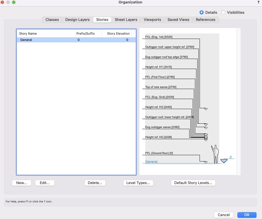
By way of illustration, here are the design layer & storey level setups for drawing I'm currently working on. NB this slightly contradicts what I said above about all DLs having zero elevation. The first floor layers are given the elevation of the first floor FFL. That's for "historical reasons" and if setting the file up from fresh I'd probably not do that. This particular project involves some planning restrictions that mean a demolished and re-constructed bit of the building has to replicate the existing. Storey levels (and associated benchmarks) have been quite useful in keeping control of this, because I can show various reference levels on the "as existing" and "as proposed" elevations and sections and make sure everything is in the right place. (In fact I am just embarking on the rather painful process of making some slightly complicated setting-out drawings on this basis. Part of the reason you have got an extensive answer to your question is that it provides a convenient procrastination activity.)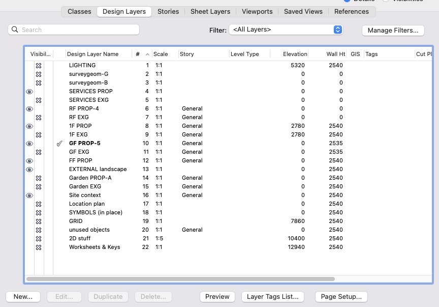
-
Multi-storey building all in one storey - would this work?
line-weight replied to line-weight's topic in Architecture
@Tom W. when you say "storey layers" do you mean "storey levels"? My setup is that I have one storey - and any design layers containing geometry that wants to take advantage of storey levels are contained within that storey. (Possibly I could just put all design layers in that storey - I don't think that would cause anything bad to happen) A typical list of design layers for me is foundations, ground floor (existing), ground floor (proposed), first floor (existing), first floor (propsed), roof, external landscaping, etc etc. I'd just put all of these in the VW "storey". For my purposes I don't use it as a storey, just a container to allow me to access "storey levels". Then I set up my various "storey levels". As you can see from the screenshots they are typically things like FFLs, FCLs, structural setting-out levels, and anything else that might be useful. I use those storey levels mainly for the elevation benchmarks that I use quite liberally on section viewports. I do also sometimes use them for binding things like wall components to. But note that you can still use design layer elevations to bind relative to (in addition to storey levels). So if I understand correctly what you've done, then no I don't think you needed to do anything other than set up a "storey", put your design layers into* that storey, then set up whatever storey levels you like. Then where you have objects already bounded relative to layer elevations, you could jsut leave them as-is, or choose to switch to binding them to storey levels instead, if more convenient. As I probably said somewhere up the thread, I quite like giving all of my design layers an elevation of zero (for ease of copy and paste-in-place) in which case when I want to bind things relative to an upper floor level, I use the appropriate storey level. But this system would not be efficient for projects with multiple repeating storeys. The other limitation (compared to layer elevations) is that not all objects can have their elevation linked to a storey level. I wish they could be - would make things like setting the height of lightswitches on a first floor a bit smoother. *never quite sure what the right terminology is: is a design layer "within" a storey or just assigned to a storey? Probably doesn't matter but I remember when I first was trying to get my head around storeys it took a while to understand their relationship to design layers. -
My setup is pretty simple in the end really. This was the thread I made when first trying it:
-
Yes I have been doing this for a while now and it's very useful. It's one of VW's best-implemented features. Just waiting for section-elevation lines to be updated to behave as nicely. Relating elevation benchmarks to storey levels is one of the main reasons I use "storeys" even though I actually just use one storey and put all of my levels (for multiple floor levels) within it. But this is all a bit off topic for this thread, which is supposed to be about getting by without using storeys at all.
-
What template file are you looking at? If it's one from the first page of this thread, note that the point of this thread is to explain a model set-up that does not need the use of stories. If you are looking at organisation/stories and seeing the "default storey levels" then if there's one with slab in the name, no it is not necessarily connected to any slabs you've drawn. You can set a storey level to any elevation you like, and you can call it what you want. The name of the storey level is just that, a descriptive name. You can then choose to relate various objects to a storey level, including slab objects.
-
I'd like it to put an X on anything that I tell it is rough timber, whether it's a structural member or a generic solid or whatever. Ideally I'd tell it by assigning it to a class, or perhaps if I get around to adopting "materials" by that route instead. Maybe there's an argument it's a redundant drawing convention. It was more important when all drawings were black& white linework. Now, because plans are so often viewed digitally, I'm gradually becoming more relaxed about using colour to distinguish materials etc and I have a specific colour/texture for rough timber. Sorry, going off on a bit of a tangent there.
-
Same here in the UK, we certainly don't use that "International" building code nor had I ever heard of it prior to reading it on this thread. We have building regulations and they aren't even the same in all parts of the UK - Scotland and Northern Ireland have their own versions. The building regulations refer quite a lot to British Standards, some of which are partly harmonised with european (EU) standards but not all of them are and some may diverge again, now that the UK is no longer part of the EU. Additionally, timber frame is not really the standard method of building residential housing in the same way it seems to be in North America. It's changing a bit of perhaps but masonry cavity walls are traditionally the "standard" approach. And where we do use timber it's often as the inner structural leaf of a cavity wall. That has implications for what happens to timber frame at details such as eaves, which will be different from what happens in North American construction. I wonder if using that sketchup plugin for a standard UK design would reveal additional limitations.
-
I was curious and watched the video below. Interesting to see where the limitations arise, many of which are quite similar to those found in VW. It certainly looks very impressive given that it seems to have been developed by one person. But it has a quite narrow focus in reality - it can deal with one particular type of wall construction, used in one rather generic type of architecture. Perhaps in the future it will be developed to be easier to use for more non-standard designs, of course. It's also clear that it's best suited for drawing up an already settled design. It looks like it would be very cumbersome as a design development tool. The main thing I wondered about was how it actually integrates with structural calculations. As far as I can see it doesn't, but there seems to be a plan to add this. It would be interesting to see how that develops, because I assume that if you are going to actually build a structural model, then there are various important ways in which the model must truly reflect reality. The various problems he solves in the video with workarounds would presumably become much bigger issues if you want to generate a model that's valid for structural analysis. And they would become more and more significant the less standard the design.
-
Problem with controlling wall texture by class in VW 2024
line-weight replied to EliM's question in Troubleshooting
This doesn't answer your question and may not be a helpful comment, but is there a reason you control texture by the class of the wall object rather than the classes of the wall's components? Most walls have a different texture each side - presumably you don't want the shingles appearing on your internal wall surfaces. -
It might be different in other places but in the UK it's the convention (at least, the convention I learned) to draw stud walls with the studs drawn in GA floor plans which might be at 1:50 (when I'd say you'd always draw individual studs) or 1:100 (I think you still would). In these cases they aren't trying to tell the contractor exactly where the studs should be, it's more a visual indication that this is as timber (or metal) framed wall rather than a solid one. When I was still drawing in 2d this tended to involve some tedious duplicating of symbols along the relevant walls, and frustratingly that remains the case drawing in 3d. In fact recently I've started not to bother, quite often, which is a compromise solution - it saves some drawing time but leaves me a little dissatisfied with the quality of the drawing. In fact in 3d it's worse than in 2d because you have to draw in those studs in the annotation space of the GA plan, which means that if you later make a new viewport say at 1:20 (when I'd definitely prefer to draw the individual studs) they aren't there already drawn - you have to draw or copy-paste them into the annotation space of that viewport. And then if you change the wall you have to go and edit annotations in multiple viewports. This is why, even if it was only a 2d representation that got drawn automatically, it would save quite a lot of drawing time. This is in the same category as the Xs in rough timber sections not being drawn automatically...things that you have to resort to drawing in annotation space that surely the computer should be able to do for me, in the 3rd decade of the 21st century.
-
It's very common to have a timber framed component as part of a multi component wall though, so I'm not sure what the benefit would be in making it something separate. What a wall object lets you do is build up and edit a multilayered construction without having to draw the different layers manually - most timber framed walls would still fall within that category. For me, as a starting point, if the timber frame layer in a wall was simply made with a timber member around the edges and then vertical members at X spacing and another material inbetween - that doesn't seem difficult to generate in a geometric sense but would instantly save a lot of drawing work that's currently necessary to make things easily legible. You'd have to make clear that the tool wasn't offering you some kind of structural solution or proposal of course but that's no different to the curtain wall tool or various other things.
