
Scott Schwartz, AIA
-
Posts
38 -
Joined
-
Last visited
-

Schedule of Values (Contractor Budget)
Scott Schwartz, AIA replied to Scott Schwartz, AIA's topic in Architecture
I'm surprised not more of the users here have this as a concern. I can tell you the Construction side of the industry does, as they/we spend an inordinate amount of time going from our BIM to a Schedule of Values. -
Schedule of Values (Contractor Budget)
Scott Schwartz, AIA replied to Scott Schwartz, AIA's topic in Architecture
@jeff prince Thanks the reply. This integration around the simplicity with specifications and construction SOV’s is a big deal to address, especially in the mid range boutique world of $5mil - $25mil projects. Specs and SOVs need to take minimal effort in this range, not a full-time staffer and CM like on a $200mil project. -
Has anyone used CSI Master Format keynotes throughout a set to then use that generate a comprehensive list of outline specifications in the CSI format to make a Schedule of Values and with quantities? This is the standard format for how all of our work is priced, and it's a manual process to go from the architecture side to the professional construction side of the business.
-
How are you placing pages of sheet specifications onto a D sheet? I’d like to be able to link to my editable Word file and have it update the contents of 4-5 D sheets in VW. I can’t find anywhere how to do this with a “live” text document, other than exporting the Word doc to a pdf then marking a slew of viewports to place, and then relocating them, when re-exporting after any updates to my original file.
- 1 reply
-
- 1
-

-
We leave them as a separate footing and stemwall (2 layers) visually intentionally, as 97/100 times they are poured separately in custom work. Board formed or exposed form ties lends itself to a 2 step pour for precision of the finished wall.
-
Stair Handrail. Custom or Settings?
Scott Schwartz, AIA replied to Scott Schwartz, AIA's topic in Architecture
Some funky work arounds for something that should be simple. I think I'll submit this to VW. -
Stair Handrail. Custom or Settings?
Scott Schwartz, AIA replied to Scott Schwartz, AIA's topic in Architecture
I got it to work with math, never would pick the Z of stair treads in any view for me, but it displays the rail above the above the break line in plan and is not a "smart rail". I'll do a polygon mask on the sheet view to hide that but what a silly workaround to get a decent, simple stair handrail with no extensions across landings. -
Stair Handrail. Custom or Settings?
Scott Schwartz, AIA replied to Scott Schwartz, AIA's topic in Architecture
@Pat Stanford I am using the 3D line mode and it still snaps flat at the Z of the layer I'm on, which leaves it under the stairs. I can calculate the ends with riser heights )plus rail height) at each end to elevate it. Doesn't seem so much like a "3D mode" to me. But it's workable for now. Thanks Pat. -
Stair Handrail. Custom or Settings?
Scott Schwartz, AIA replied to Scott Schwartz, AIA's topic in Architecture
@Pat Stanford Thanks. I guess I'm missing something in fence mode. I have had the rail off in the Stair Object. I have been using my own rail object than I have shown. When I draw a rail, it's flat at the Z of the layer I'm in. Not seeing how I pick two different Z points on stair treads to make it follow the angle of tread nosing. Then I could at least add 36" to each Z value to get it at the right height. I see I am able to do 3d line mode then calculate the end of each end with math. Would be nice if it at least snapped to stair treads. Any ideas on how to do that? -
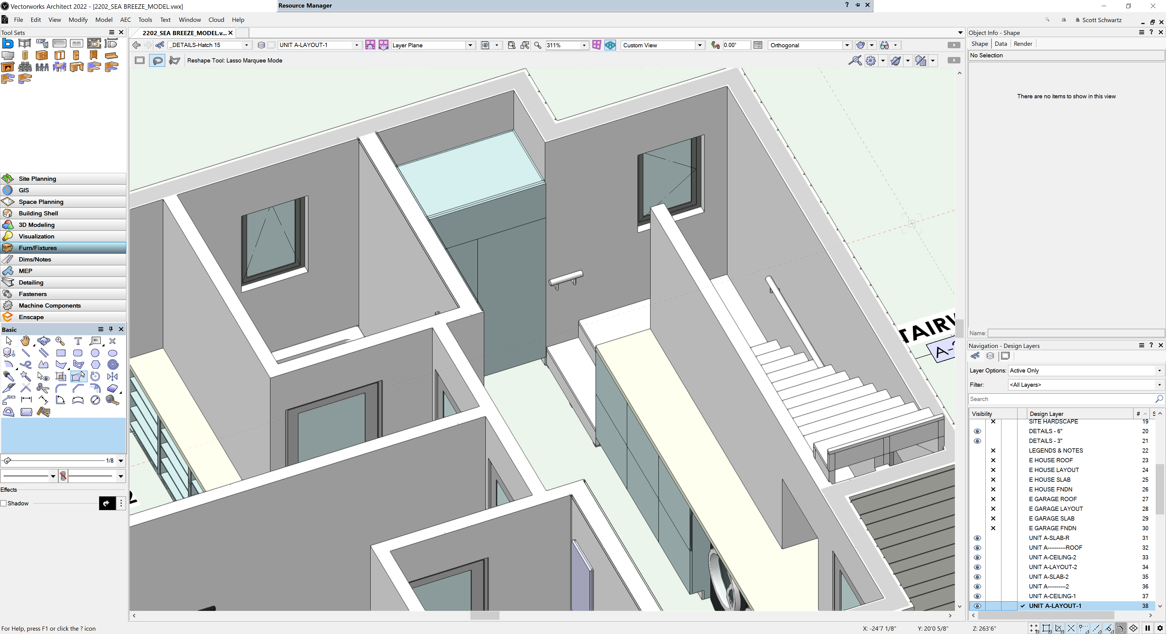
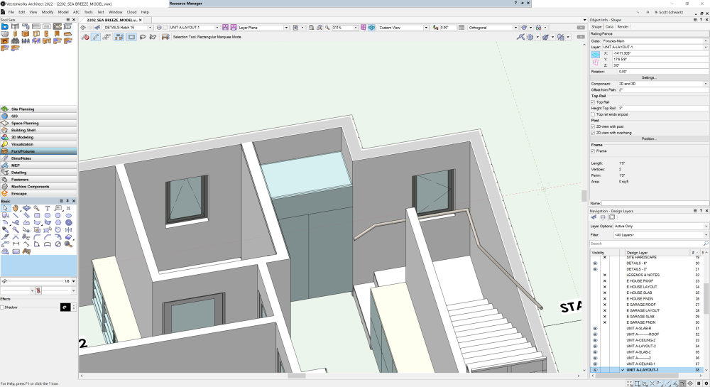
How can I get the railing to not occur on landings? This is NOT how we want hand railings: I setup a stripped down railing with fascia mounting that looks more like what we install below . How do I get the Z values on the ends?
-
Show Section Marker in Elevations Viewports?
Scott Schwartz, AIA replied to Scott Schwartz, AIA's topic in Architecture
@line-weightThanks. I used the section viewports to produce my elevations as there are multiple structures, site work and retaining walls around the site to get grade at the building. I will try the other "view ways" out on a simpler building. I guess a clip cube view could help? -
Show Section Marker in Elevations Viewports?
Scott Schwartz, AIA replied to Scott Schwartz, AIA's topic in Architecture
But they could move, like a Grid line does, if VW programmed it to. The section markers already live on the same design layer as the grid so I can display them in any plan view. -
Show Section Marker in Elevations Viewports?
Scott Schwartz, AIA replied to Scott Schwartz, AIA's topic in Architecture
Thanks. It's as if VW doesn't talk to experienced architects when they setup a tool's features and functionality and how we really use it. -
Show Section Marker in Elevations Viewports?
Scott Schwartz, AIA replied to Scott Schwartz, AIA's topic in Architecture
@Pat Stanfordit appears "Section Line Instances" only displays Plan view ports. None of my named Elevation Viewports show up in that list. Bummer. -
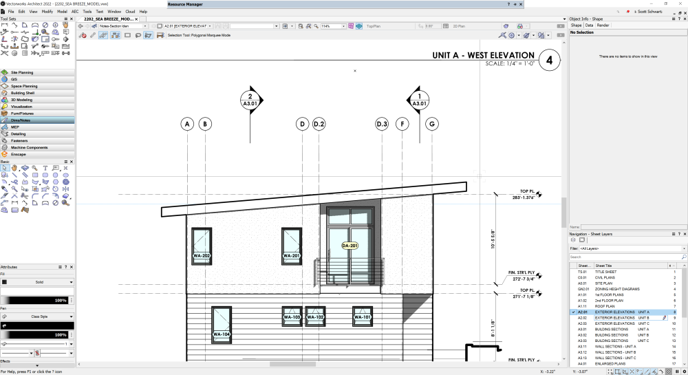
As the title says, I want Section Markers showing up automatically in elevation viewports, as easily (cough cough) as grid lines/ bubbles do, even with the graphic manipulation needed. All my section marker classes are on in the VPs. I know I'm missing something utterly simple. Thanks. These shown here are manually placed (and properly linked thanks to @Matt Panzer setting me straight). This will be a royal pain with dozens of sections to manually locate.