Search the Community
Showing results for tags 'modelling'.
-
Hi All, I'm gradually getting to grips with 3D Vectorworks, but still finding some simple things frustrating, and I'm sure its just my lack of knowledge! Is there a way to move things to a specific 'global' z height? For instance, I want to move an object to sit on 'z=0', but there is a bunch of geometry around there which makes it hard to snap precisely. Or, I want to move the object from within an awkward 3D view. Any tips or advice?? A
-
Hi, I use VW but two of my colleagues will be modelling in Sketchup. Are there any tips on workflow? Ie guidelines on how to best export and import? In the past I have found models I've imported in VW from SU to be very fragmented and need a lot of cleaning up. The person I'm working for will model in Sketchup and then ask me to import the model into VW to produce working drawings He'll also want to make changes to the model (in VW) and then also texture and light for rough renders. Then pass the model back into SU Is this possible? or better to just transfer it once from SU to VW. Any tips on how I can save hours remodelling / fixing up the model so it is editable in VW? much thanks, Helen
-
Hi everyone. I am fairly new to VW with previous software experience mainly in ArchiCAD. I am working for a practice and we've discussed having multiple users in a single file/model working at the same time. Now, in ArchiCAD there is a Reserve and release method, where you can research elements of the model to draw, and request to use reserved components from other users, where they can than release, freeing it up to use. Does VW offer a similar method, to allow for multiple users to work from the same file at the same time? Thanks in advance
- 14 replies
-
- bim
- architecture
-
(and 1 more)
Tagged with:
-
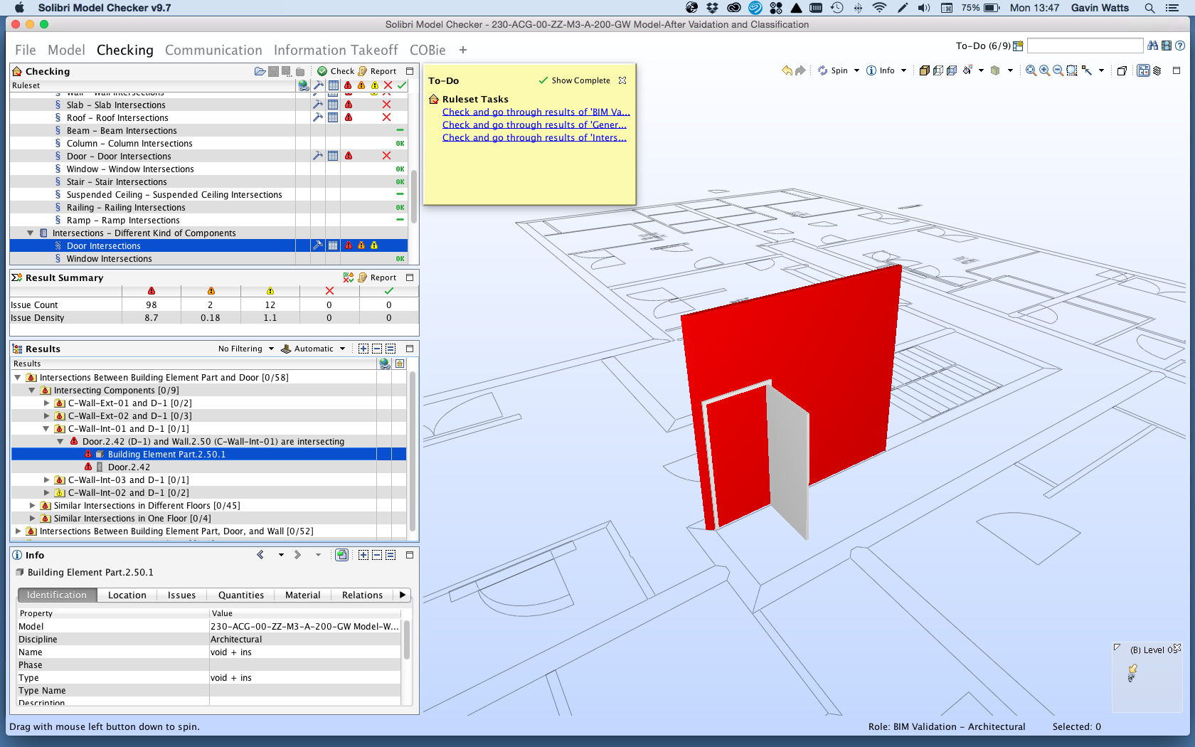
Hi, I am currently working towards PAS1192:2-2013 mandate and I am having some issues with the IFC import and the way we create windows. As we work on large housing schemes we work with window types, a method Vectorworks have previously advised to do it. So we create windows and then turn into symbols, so when placed within a wall they appear as a 'symbol in the wall'. However when exporting to IFC and either re-importing into VW to test or into Solibre Model Checker, the IFC format does not acknowledge the relationship between the wall and the window. I therefore tried exploding the symbol to test if it was this and when it is a 'window in wall' it views fine. I was wondering if anyone has had a similar issue and a work around. One way i was going to try was using symbol geometry in the window settings. therefore if you change the original source component then this will still change. However this will result in manual window changes to each window for height width etc. I have attached a solider model checker screenshot showing the if import result of a door in a wall as a 'symbol in a wall'. This also applies to doors. Thank you. Gavin
-
We received some 'Enscape 3D' links from a consultant we're working with this week. These provide interactive 360 degree navigable views from a set point on their model which open via weblink, so would be something we could send to clients etc without them having any modelling or visualisation software - and looks to me like a plugin which works with Revit / ArchiCAD. Is there anything comparable at the moment for Vectorworks, or is this something that could be incorporated within Vectorworks itself? Thanks, Lisa
- 3 replies
-
- visualisation
- interactive
-
(and 3 more)
Tagged with:
-
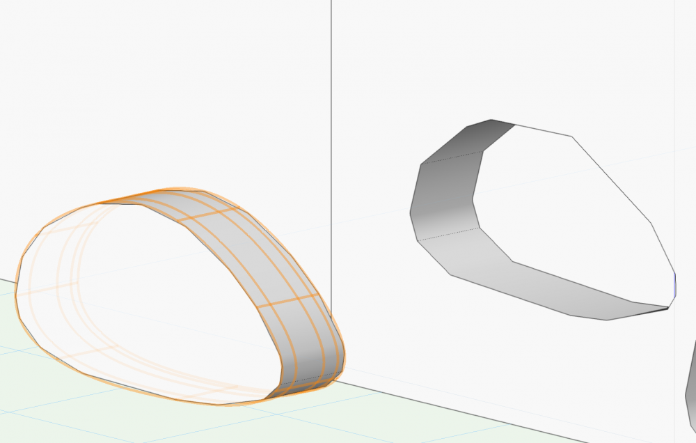
Hi everybody, I am newbie Vectorworks user. I just signed up to the community to hopefully figure out a problem I am having with the so called Hybrid Object. Starting from the bottom, I have created a solid by subtracting a simple solid (cylinder) from a negative void of a second solid as in the image. This apparently resulted in what is an Hybrid Object. As I want to further model the 3D form Vectorworks warns me with the following message: "Hybrid Objects can only be rotated in a plane parallel to the active layer plane.Would you like the working plane set to the active layer plane?" If I say yes, the working plane is automatically set to make the object rotate on the Z axis. Instead I am looking to rotate it on the axis which will position it flat on the larger side. I hope I have been clear enough but If I wasn't please bear with me. Thanks, Flavio
-
Hi all, I've used Vectorworks for many years, but only to do 2D work (plans, sections, construction drawings etc.) and am pretty confident at it (at least the bits that I use!). I would like to start using it for 3D. At the moment I use SketchUp to create a model, then Photoshop for post-processing. I would probably stick to Photoshop for some work, but make use of much better rendering within VW. I am hoping that there are people in the same position as me who have some advice, tips and resources to share, as I pretty much plan to teach myself, and would like this to be in as efficient a way as possible. Are there things you always wished you knew? Have you found any amazing blog posts or tutorials? Are there libraries of textures or objects that you'd recommend? All advice would be appreciated - I have a good project to learn on, and excited to get started! Thanks! Fi
-
Hi, I am looking to model a simple pond / swale but can't seem to figure out the best way to do it. I can create a site model using the highest and lowest contour easily, and that gives me the shape I desire but the volume is incorrect as it measure that which is on the outside of the pond and not, if you can imagine, what the pond can hold. Any tips for creating this? Many Thanks S
-
I have created a slab style that has the flooring, floor joist, ceiling battens and ceiling. It works great apart from the edge texture can't be set. As per the image below is it possible to create an additional component that can be classed the same as external walls and that sits in the same Z height as two of the other components.
-
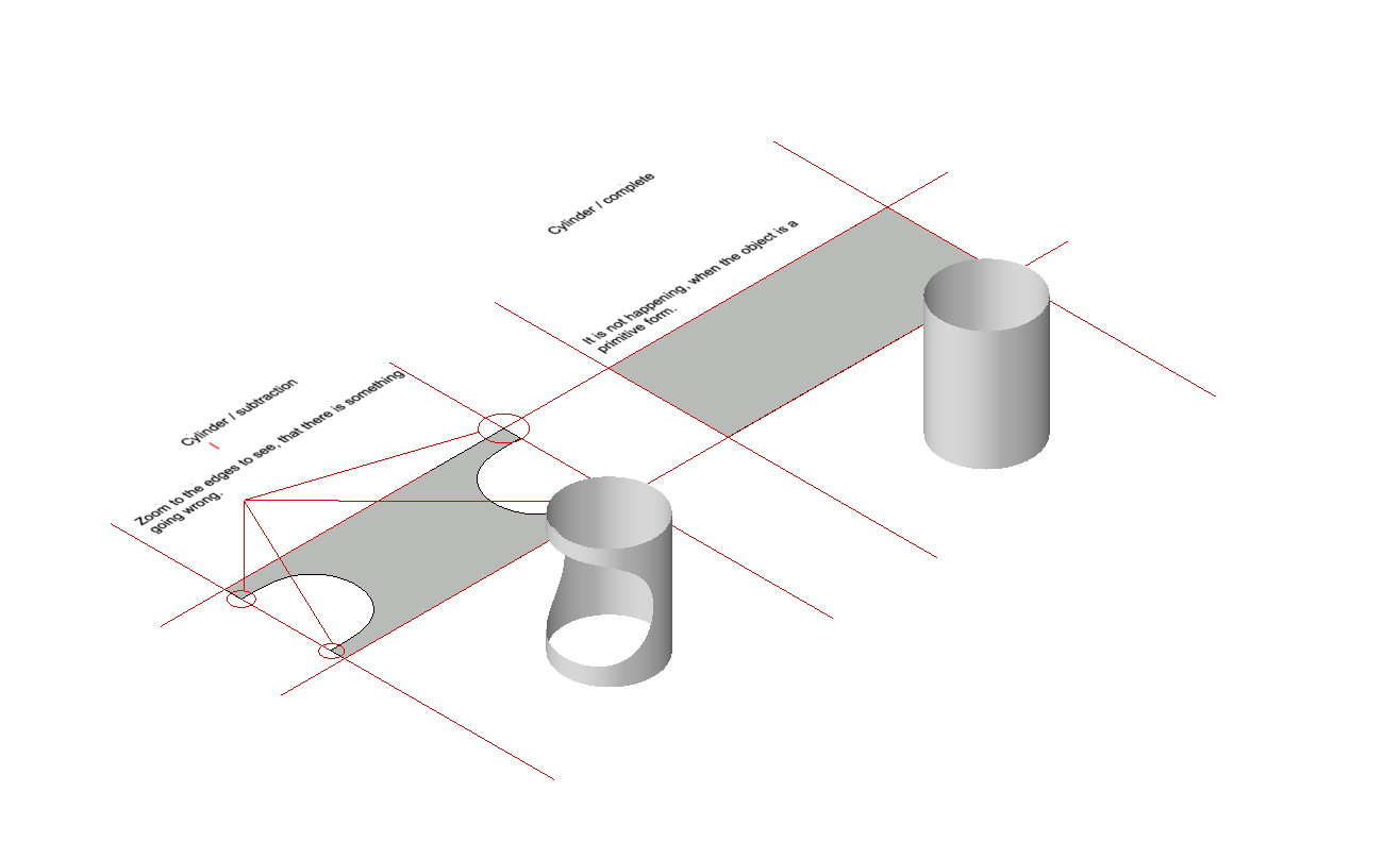
Hi there, lately I am working a lot with the tool "unwinding plane" (don't know how it is called in english). I encountered, that if it is a cylinder, everything is fine, but if this cylinder has something cut out, the plane is a little off on every side. Sometimes visible without zooming in. So the problem is, I want to send this data to a laser cutter and it has to be a 100%. Could someone explain why this is happening? To me it is a more or less simple mathematical thing like pi*D. If you want to test it on your on, just create a cylinder and another one where you cut out something. I used that same cylinder just flipped it 90degrees. Thanks in advance!
-
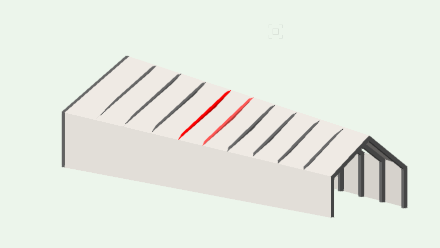
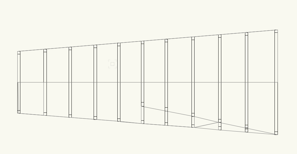
Hi, I'm designing a building which is based on a simple barn extrusion, however this is complicated through the building fanning out in plan and an angled pitch of the roof. Please see attached screen shots. I believe the change in angle and height of pitch is creating a very small hyperbolic paraboloid roof structure (if very small). I would like to model this roof which allows for a fairly easy change as the project evolves (still in early feasibility stage). I am fairly new to modelling in 3D in Vectorworks (used to 2D) and would very thankful in any help in modelling this roof. Many thanks, Christina
- 4 replies
-
- hyperbolic paraboloid
- roof
-
(and 2 more)
Tagged with:


