Christina
-
Posts
2 -
Joined
-
Last visited
-
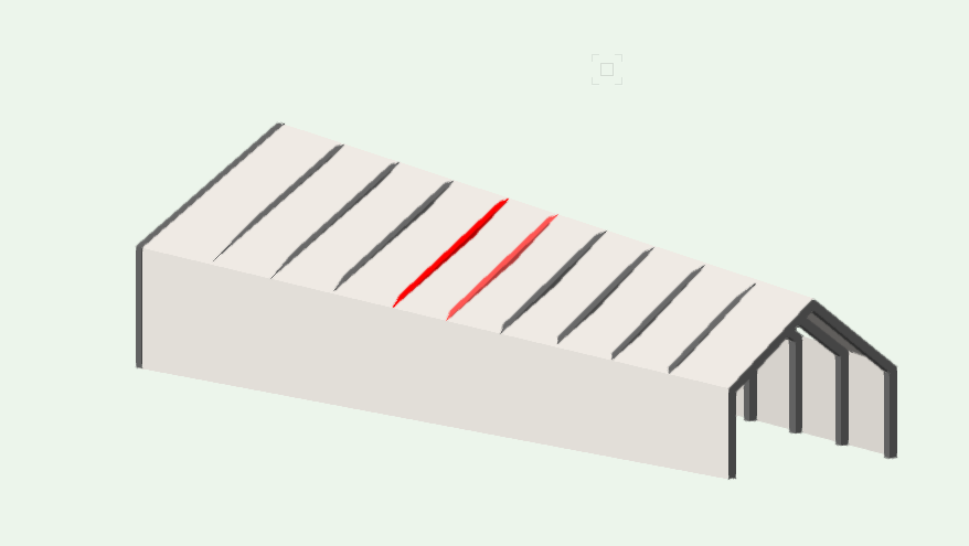
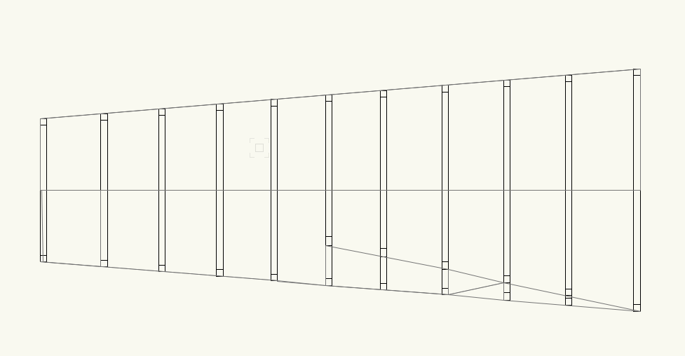
Hi Robert, Thanks for your reply. Yes, the two gable ends are different in both height and pitch (hence creating the hyperbolic paraboloid). The structure is modelled by drawing each rafter after corresponding heights from elevation and plan, as individual polygons, which have then been extruded and placed in the right location in plan. I think I have already tried your second approach where the roof was modelled as a roof face to the right pitch - however, due to the two different angles of the pitch at either end this isn't possible. Are you suggesting to use the "Roof face" under the AEC menu? Many thanks!
-
Hi, I'm designing a building which is based on a simple barn extrusion, however this is complicated through the building fanning out in plan and an angled pitch of the roof. Please see attached screen shots. I believe the change in angle and height of pitch is creating a very small hyperbolic paraboloid roof structure (if very small). I would like to model this roof which allows for a fairly easy change as the project evolves (still in early feasibility stage). I am fairly new to modelling in 3D in Vectorworks (used to 2D) and would very thankful in any help in modelling this roof. Many thanks, Christina