Search the Community
Showing results for tags 'modeling'.
-
Currently, after drawing a seating aisle path, the only way to edit it is in a mode which hides everything else. This makes editing a drawn path near-impossible, and it is often easier to just delete the path and draw it again, since one is often drawing around existing objects in the drawing. The aisle tool should allow edits to the drawn path that do not hide everything else. Even better, there need not be a separate mode for editing them - it would be fewer clicks if, like many other objects, selecting them would bring up resize handles. Same for seating sections.
-
Right now when using the 3D modelling tools, like for example the push-pull tool, it also works on 3D symbols. Turning the 3D symbol into a solid.. So we really have to check all the time if we are editing the 3D symbol. Otherwise you make it a solid by accident. An option to disable this, or a message saying that you are turning a 3D symbol into a solid would really help. Some illustrations Step 1 - 3x the same symbol Step 2. - using the push pull - but forget to open the symbol edit mode... oops, it turns into a solid.. Step 3 - but this is what I wanted..
-
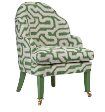
Hi, I am struggling designing this armchair -not the legs or cushion but mainly the back and side. Does someone has a way of doing this efficiently? For the cushion I would use subdivision to create the plumpness but for the back, I am totally stuck as there is this curved shape that goes up in the middle. Any tips would be appreciated! Thanks
-
Hi, is there a way to simulate how the fabric behaves? And by that I mean, for example, when it hangs from different points (think of two people holding a blanket, how you get the curve for the fabric and how it folds). Bernat
-
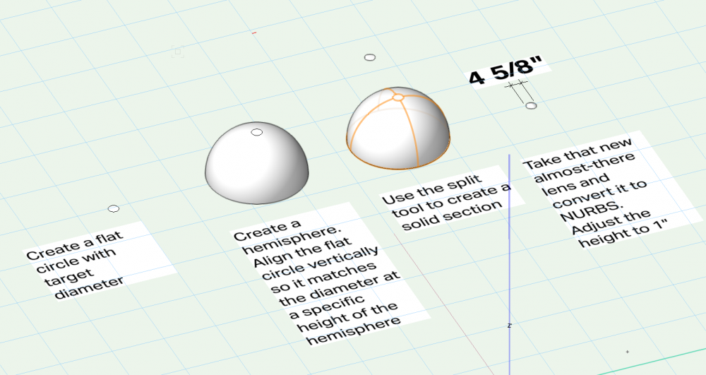
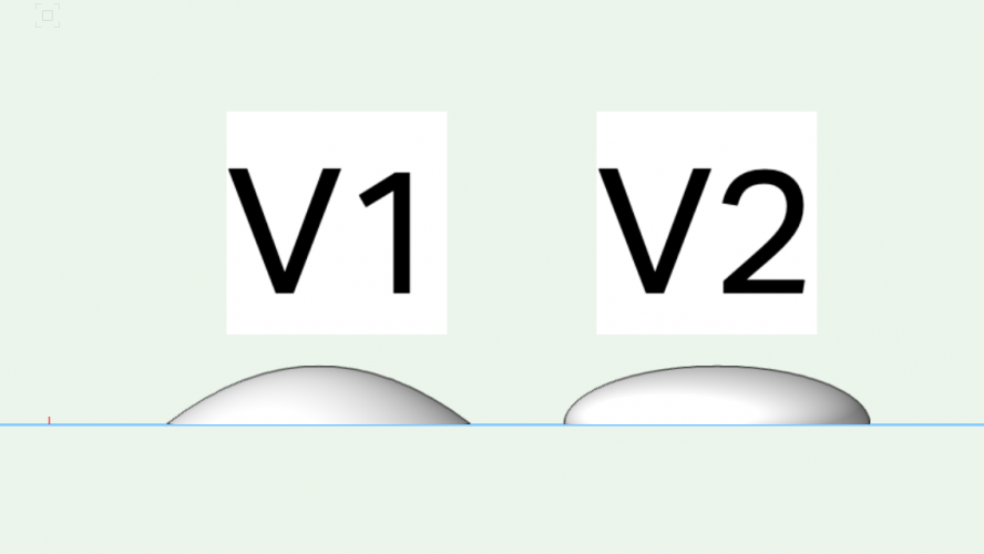
I want to create a lens that is 4.66" in diameter and 1" tall. The way I created it was: Create a flat circle with target diameter Create a hemisphere (diameter doesn't really matter, just needs to be a lot bigger than the flat circle) Align the flat circle vertically so it matches the diameter at a specific height of the hemisphere Use the split tool to create a solid section Take that new almost-there lens and convert it to NURBS Adjust the height to 1" If I instead: Create a hemisphere at 4.66" in diameter Convert to NURBS Adjust the height to 1" I end up with more of Pancake shape (V2) then a lens shape (V1): Does anyone have a recommended workflow for this?
- 2 replies
-
- modeling
- projectors
-
(and 1 more)
Tagged with:
-
Is there a way to add the convert menu to the right click behavior when clicking on an object?
- 4 replies
-
- efficiency
- modeling
-
(and 1 more)
Tagged with:
-
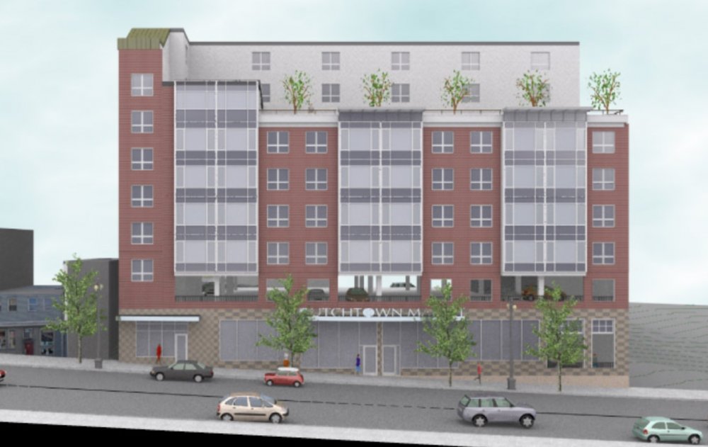
Greetings Something to ponder over the holiday: I have a 7 story mixed use building created in 2010 (i.e. no stories) It was a developed schematic design (all floors modeled, elevations and sections taken and rendered) Many duplicate apartment units which I made into symbols with some strange elevational results but it all held together for what was needed. 7 or 8 years later (now) the project may be coming back to life. I suspect many changes will ensue including story heights. I spoke to VW support and they suggested that I not move to stories due to the complexity of transferring the model layer by layer and the complicated setup. I currently use stories for literally everything (even single story additions, even though levels and walls can be cumbersome at times.) I have found when it works, the results are a real time savings. Anyone have any experience/thoughts/insights on something like this? Steve Steven Glickman Architect 400 Northampton St, Suite 500 Easton, PA 18042 V: 610.253.6536 E: stevenaia@gmail.com http://www.stevenglickmanarchitect.com
-
Hello, I'm trying to deform an object on an axis using the 'bend' mode. However, it will only let me bend from a point that I pick on the object. How do I set the axis somewhere else, so I can bend on a different plane? Thanks
-
Currently I'm trying to figure out ways to modify the sweep I just created. I want to trim/cut a section of it off. However, if I convert the sweep to anything such as a solid, the sweep turns into a filled solid. How can I convert a sweep into a surface and thus trim the section off from the new surface?
- 1 reply
-
- sweeps
- 3d modeling
-
(and 2 more)
Tagged with:
-
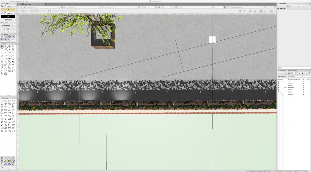
I will confess that I'm not that efficient with light sources to the point where I can't get a custom source to show light in any rendering mode. I'm working on a project where we will be providing path lighting with small fixtures fit into new planters. I've modeled that planter to include the a standard "flood" and as you can see in the screen shot some of the are showing up while the same exact symbol suddenly stops rendering the light. Is there a limit to the number of light sources or some setting that I'm missing? Any help will be greatly appreciated!
-
I’ve wanted to figure out how to model this for years and couldn't find a solution till now. Window surrounds that included brick stacks (the bricks that run along side the windows), the brick sills (sometimes called rowlocks), the brick soldiers (the taller bricks that run along the top of the windows) and the keystones (the sandstone shape in the middle of the soldiers). This is how I did it: - Window symbol was put (in the window class) and gave it my desired width/height specs. - I gave it a exterior trim roughly the width of a brick (3.67”); made it very thin (1/16”); and turned off trim under the window. - I assigned a brick bond texture (with a brick bond hatch) to the exterior window trim class. So far this gives you a window with brick side stacks and trim above the window that will soon be covered up by another piece. - Then I duplicated the window in place; turned it into a cased opening; made the jambs, trims and sashes all 0”; - I turned on the “lintel” and gave it an 8” ht. ( the ht. of a soldier); and an 1/8” ext. protrusion (so it sticks out proud of the top window trim). - I assigned a brick bond texture (with hatch) that runs vertically... to the "lintel" class. - I turned on the “sill” and fooled with the specs till I had it where I wanted it. - I assigned a brick bond texture (with hatch) that runs vertically (it might be the horizontal brick bond that works) to the "sill" class. - I also increased the width of this duplicate window symbol (wide enough for the lintel above and sill below to line up with the edge of the window trim on the main window symbol). - I may have fooled with the ht. slightly so that lintels and sills all aligned properly with the ht. of the main window symbol. - I changed the class on this duplicated window symbol to “non-plot” so that it would not show up on the window schedule - Lastly, I extruded a keystone shape (these vary in size)…I made mine a little taller than the soldiers…and slid it into place.
-
Is vectorworks an effective software for BIM? the firm is looking into moving towards it, for those who have experience is it worth it?
-
I've used Vectorworks since it was known as MiniCad. However, 90% of what I do in Vectorworks is 2D. I've actually started using Chief Architect for residential BIM since it seemed to fit residential more directly - using Vectorworks primarily for concept work and graphic presentations. Id love to learn more about residential BIM inside Vectorworks. Are there any good sources for this? Thanks in advance.
-
Was not sure into which sub forum to put that thread (modeling, architecture, rendering). Whatever the reason was for that project, like bringing hidden modeling tools like surface arrays backt into our minds, I think that is the most aesthetically pleasing VW project in so far. In terms of underlaying architecture, rendering and to carry an overview of VW tool set. I have some more questions about that project : @Luis M Ruiz: In the video it looks like you are modeling in a kind of freehand way without numeric input, just by proportions. Was that the case or were there any dimensions laying under that we just do not see in the video. could you please elaborate on this and what were your sources like plans or photos ? And could you go a bit more in detail about your material and render settings ?
- 8 replies
-
- richard meier
- jubilee church
-
(and 2 more)
Tagged with:


