-
Posts
222 -
Joined
-
Last visited
-
@Daniel OKane I wouldn't call it a training video, but this webinar, presented by landscape architect Anna Arbetter, does show workflows her firm, Futurity, uses when making use of importing tree data in the form of the existing tree objects. https://university.vectorworks.net/mod/scorm/player.php?a=173¤torg=articulate_rise&scoid=346 . Also, this video, which you can also view on YouTube https://youtu.be/NXUjlQHbNZA?si=h6Dd14J9k8MULo9C shows a new-ish feature, introduced to Vectorworks (because of the wishes Anna and David of Futurity) which enables the importing of tree data via GIS to make existing tree objects in Vectorworks. Thanks for reaching out about this feature. Best regards, Eric @Katarina Ollikainen
-
machi started following Eric Gilbey, PLA
-
Hello Site Design Forum family. Almost two years ago, I proposed a question about real-time rendering solutions which gathered some really great responses. Since it has been 2 years, and technology advances have been non-stop, we would like to ask again what your real-time rendering solution of choice may be, if you are not solely relying on Vectorworks for your site design rendering. Of course, we would love to see examples, and if you are excited enough to share your story, we may just tap into your expertise by asking to host a coffee break, you tube video or webinar...or contribute to a blog story or media article. If you are considering the implementation of a real-time rendering solution, or moving from one to another, which one are you considering? Thank you for your consideration and responses. Best regards, Eric
-
Hi Åge. in the Landmark pull down menu is a command called Grade Limit from Pad. This allows you to set the batter slope. The reverse option, Pad from Grade Limit allows you to also set the slopes and it attempts to balance your cut and fill. You may want to refine the shape of the pad once it has been created.
-
@Michal Zarzecki I have not considered that, but you may be right. Every time I have done this, I was in a 3D view to make sure the site model object (3D lines) was what was selected. I'm glad it is working for you now, and I appreciate you letting me know.
-
Hi Michael, First, I made sure just the site model was the only design layer visible... Then Exporting Vectorworks classes as DWG layers... Then under objects...only selected objects (make sure the site model is selected). Then click ok...this seems to work for my export...if it is not working for your export, perhaps check in with tech support to see what may be triggering your error. Let me know what becomes of your attempt, Michael. Eric
-

Resource Manager items vs Hardsacape Tool
Eric Gilbey, PLA replied to Marcus bLD's topic in Site Design
Hi Marcus. If you want the fastest route to find the Hardscape styles from the Resource Manager, in the search field, in the top of the resource manager, type in hardscape, and hit enter. You should see these pop up immediately. You can click through the folders on the left where the Vectorworks libraries are held…you’ll find them lower in the list where there are site objects. One feature I love is found when you activate the hardscape tool…once you click on the hardscape tool from site planning tool set, in the mode bar at the top, you will see what we call the resource selector pull down menu which may say “hardscape style:”. Once you click into that pull down, you will see what looks like the resource manager, but it is only revealing hardscape styles. At the beginning, you will find the ones Vectorworks has provided…once you have added your custom made hardscape styles, you will see them there too…just in your favorite or user folder. Hope this helps. Eric -
Hi Tom. I cannot say there is a change in this as of yet, other than the fact we have new 3D content with Laubwerk plant representations. I will also tag @Katarina Ollikainen and @Scott Lebsackin this post as they are both involved with the styled objects' development and can speak to the ability to generate day/night appropriate image propped plant styles. Stay tuned... Eric
-
João, I will make note of this, but hopefully you will see that starting with our version which released in September (v2023), a terrain model exported from Revit is treated as a site model in Vectorworks. There is no longer a need to convert their mesh to 3D polygons and create a site model, it is automatic. Similar to how their smart objects like walls, slabs, doors, windows, etc are treated as Vectorworks walls, slabs, doors, windows, etc.. Though Autodesk is not seeking to treat our smart objects as true BIM objects in Revit (we can't control their software development to better manage our geometry and data), Vectorworks is doing just that with the objects imported into Vectorworks from Revit. As you can imagine, Autodesk would not really allow other CAD/BIM solutions to create objects which are treated as native Revit objects. Thanks again, Eric
-
João, First...what are you experiencing in exporting your site model to RVT for use in Revit? Second...there should not be a need to explode (ungroup) the site model to get 3D contours out of it. You can change the 3D configuration to be 3D polygons, then export to DWG. Last...you can copy the source data, paste in place outside of the site model, then Choose Landmark Pull-down menu; Select Survey Input; Select 3D Polygons to 3D Loci. This will create the 3D Loci which you could also export. If you need the proposed contours instead, you can right click, and choose edit Proposed Site Model Contours. Copy the contours and then paste in place. (It may give you labels as separate objects, you can use select similar to remove them) then run the same process as above to get the 3D loci. Now, if you still need to generate a CSV report to export for the Revit user, you could do the report on 3D locus, and you will have to "Select from: Functions" in the Columns section of custom report dialog...and choose Xcenter, Ycenter and Zcenter for the report....then export that report to CSV. As you can see its a bunch of steps but possible...this is why I would suggest the 1st or 2nd options. Hope this helps. Eric
-
Tobias Kern started following Eric Gilbey, PLA
-
Irina started following Eric Gilbey, PLA
-
Hello site designers. As you know we have invested in creating tighter connections with real-time rendering applications like Lumion, Enscape and Twinmotion. We are looking for some examples of the work you are doing which involves these connections. Along with that, we would love to hear how these connections have benefitted your workflows in going from design to presentation. Please let me know if you have examples and stories to share. Of course, you could reply here...or, you could send me a message here in the forum...or you are welcome to email us at landmark@vectorworks.net . I look forward to hearing from you soon. Best regards, Eric
-

Classes and layers for landscape?
Eric Gilbey, PLA replied to Anders Blomberg's topic in Site Design
Hi @Anders Blomberg I have recommended layers be used for visualization hierarchy (think stacked layers of mylar/vellum with each design layer containing areas of work. For example, From top to bottom...Upperstory planting, building, constructed features, understory planting, surfaces, terrain, base plan, survey, aerial. You could also apply phasing, alternative designs, etc this way. I recommend classes to be the drawing tool (they line color, lineweight, line style, fill, etc) for elements and/or their components. Many still will apply design layer-like treatments like making a class for plants-proposed vs plants-existing while there are still plants-component classes. This is up to you, as you could easily do that with design layers too. -
Scott Lebsack started following Eric Gilbey, PLA
-

What the heck does this mean?
Eric Gilbey, PLA replied to hollister design Studio's topic in Site Design
@hollister design Studio you are correct...not your library...its the place where the plant data originates if you are using it...if not (sounds like you are not), you are all good. -
@Tom W. Thanks for bringing this to our attention. I did not see the prior comment until you called me out for this, so I appreciate your follow-up. I will bring this to our development team's attention to see about fixing this issue.
-
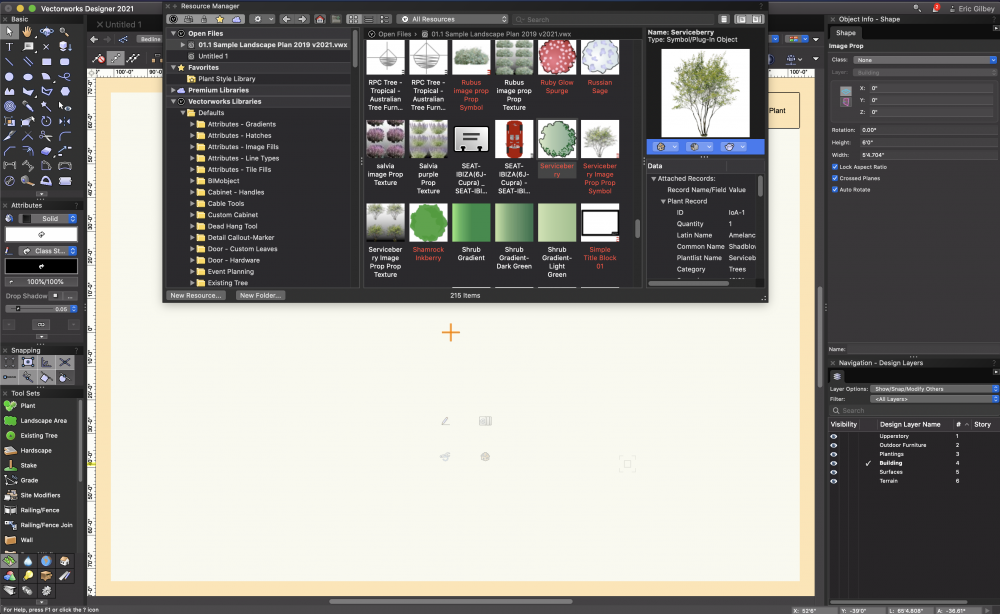
Hi @Tom W. There is a way to disable the cross planed image prop...if you right click on the plant in your resource manager, or in the plan, you have options to edit the plant style...choose the "Edit 3D Component". This will give you the image prop, which you can select. Once selected, the OIP will display the options, and it is here where you can disable the "crossed plane" option. See the image attached here. Hope this helps...let me know if otherwise. Best regards, Eric
-

What the heck does this mean?
Eric Gilbey, PLA replied to hollister design Studio's topic in Site Design
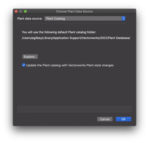
@hollister design Studio Hi Bruce. This message happens when you have the linkage between the plant and the plant catalog activated. I'm not sure if you are still using Landmark 2021, so I am going to show this response with 2021...if you are doing this in 2022, it should be the same. In the Landmark Pull-down menu at the top of the screen, you will notice an option at the bottom of that menu that reads "Choose Plant Data Source". If you click on that last option, it will open a dialog box that gives you an option to turn on/off that updating action. (see image attached) This option is likely defaulted to be on so that designers who want changes they make to the plant data to go into its record in the plant catalog. If you are not using the plant catalog, then you should disable this checkbox...if you are using it and want your changes to update that catalog record, then keeping it checked would be best. Now...as far as why its triggering that response...if you have changed any of the data it would recognized from the original record for that plant, it will say it can't find that plant (record). For instance, you may have decided to pick a variety of Rosemary that is different than the record chosen in the plant catalog...if you change or add a variety/hybrid name, it won't recognize that plant record...you can add it in (recommended if you are actively using that plant regularly), or you can say 'no'. I think if you want to update the plant catalog with multiple plants at once, you can disable the check box in that dialog mentioned above...then when you are ready to do a full sweep update to the plant catalog, then use the same Landmark pull-down menu and choose "Update Plant Data". This will take all of the plants in the file and update the plant records in the catalog. Be careful...if you choose the next option, it will take the data from the catalog and update the plants in the project file with what was on the catalog records. This last option may be preferred if you think the plant information from your symbol library is not as current as changes you made to the catalog. Hope this helps....let me know if otherwise. Best regards, Eric


.thumb.jpeg.48a6fdc44e48c98b8e1b507e86e57e95.jpeg)


