markdd
-
Posts
3,412 -
Joined
-
Last visited
Content Type
Profiles
Forums
Events
Articles
Marionette
Store
Everything posted by markdd
-
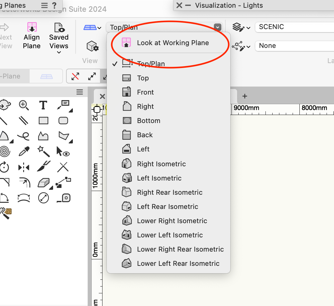
I don't know what the exact rationale is for the menu option. However, there is always the menu command to which you can add a short cut as well as a Right-Click Working Plane menu option if that is how you like to roll. Personally, I find going to the View Bar a bit of a chore and use a keyboard shortcut to activate the command instead.
-
Using "Base Plates" with papes and truss's
markdd replied to Cristiano Alves's topic in Entertainment
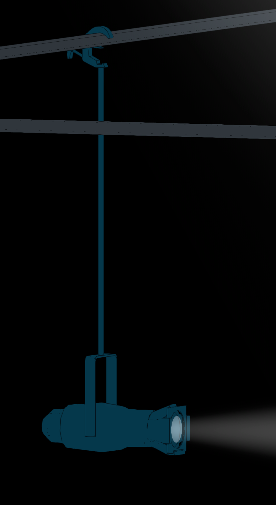
Because I nearly always take schematic Views from Booms such as the ones in the image above, I attach all my rigging hardware apart from clamps as Point Loads. These include Boom bases, Side Arms, Hanging points, and anything that will constitute a finished boom. I have a "boom kit" resource folder with pre-made point load plug-in objects that attach to booms and that will automatically show up in Schematic Views. I discuss this approach at the end of this webinar I did during lockdown and you can find it here. -
You can make them bigger in VWX preferences. I have been working with the new UI for about 6 months now and once you get used to the new icons you'll wonder what the problem was....
-
The objects are already Groups and not Symbols at all. If you double-click on the group you will be taken to the Group geometry where you can edit it at will. It looks to me like you have imported the whole DWG file as a single Symbol. That may be what is confusing you?
-
I am not sure what is not working. Are you sure that the object you are selecting before running the Convert to Group Command is a Symbol?
-
There is another command called Convert to Group in the Modify>Convert menu. I think you have activated the Group command.
-
When you resize an instance of a symbol it should be considered as a one-off alteration. If you go to edit the symbol, then you will be editing all instances of the symbol definition in the same way that AutoCAD does. When you go to the edit Symbol Window, you will be seeing the original unscaled geometry, hence the size difference. If you want to edit the geometry of a symbol as a one-off, then it is probably best to Convert it to a Group which you can do using the Convert to Group command then the scaled geometry will be disconnected from the Symbol geometry and you can do what you like with it.
-
How to copy and paste with base point and insertion point
markdd replied to Camila85's question in Troubleshooting
You can paste an object directly on to the last point you clicked in the drawing area and a symbol/plugin will paste using the insertion point as the reference point. All other objects will paste at the centre of the object’s bounding box. There is the Paste in Place command which will paste the exact coordinates of an object from where it was copied from, but that is probably not what you need right now although is worth knowing about. As @Tom W. suggests, the Move by Points tool will probably give you the functionality you are looking for. -
Ha. This is exactly what I eventually came up with! Thanks for taking the time.
-
I eventually came up with a solution that was rather convoluted but did actually work. I’ll do some digging and see if I can find the file. I’m doing very long days at the moment, but I’ll pm you if I find it…..
-
Try this

-
You could also run the Convert Copy to Polygons/Lines command from the actual view you want to see. It's not perfect in that it won't immediately align the geometry to the Screen unless you turn on the Legacy Screen Plane functionality. However, it will at least skip the Viewport Steps and the rescaling but will mean that you have to run the command for every view you wish to see. "Horses for courses" I guess...
-
This is what I do: Use the Multiple Viewport Command to create the viewports Convert the Sheet Layer Viewports to Groups. (ctrl K) Then you you will have the line geometry in groups. Rescale back to 1:1 and assign the groups back to a design layer. (You may need to assign the geometry inside them to the Layer Plane as well.....) Arrange as you see fit.
-
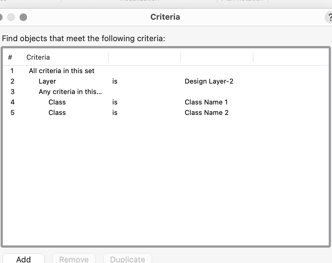
You need to specify the Classes in the Custom Criteria. ie Any Criteria in this set Class is ... Class is ... You can choose from a list of Classes there. Remember that Worksheets are not Spreadsheets and you can't delete a row. All the rows are generated by the Criteria section above. What you are doing in the Criteria section is choosing what objects you would like the Worksheet to display the data from. If you need to narrow the criteria (by attempting to delete a row), then you need to narrow the criteria from the start. So the Criteria will be as above and then Column A will be =Class and Column B will be =Count You need to make sure that Column A is set to Summarize and then Column B should return a count of the items. If you want to add multiple data Base Headers, I.e. another Class later on, then Right-Click on a Clean Row and change it from Spreadsheet to Database and you will then be asked for more criteria. I think that's clear and I am sure that other folk will add to this.....😀
-
As I see it there is only one simple solution. Build your wall as you have been doing (without your extra extruded geometry). Then use the Extract Surface tool (4th mode) to extract all the screen surfaces. Hold down the shift key to make a multiple selection. Press enter or use the checkbox in the mode bar. You should have a bunch of NURBS Surfaces inside a group. Enter the group Run the Add solid command so that they are all one object. Then all you need to do is add your single Image Texture to the combined surfaces and with a little mapping you will be done. A couple of tips: In order to avoid Z fighting of the screen and the solid textures I would put a clear texture into the screens. Use Cylinder mapping for the Solid Texture. Any other mapping type will give odd results
-
Truss symbol 3D duplicate - What is the intention?
markdd replied to Stefan B.'s topic in Entertainment
The 3D Symbols are generated when a Truss object is rotated around the X and Y axes and are used as substitutes in the Truss Object. If you make a change in the Hybrid version (from where the 3d object was created) then it won't be updated in the 3D-only symbol. I agree it's untidy and leaves a mess in my resource manager as well. It also feels like a workaround that I wish could be made more elegant. It's all to do with the Hybrid nature of Symbols and the fact that the Truss Plug-in does not generate 2D geometry when you rotate a Truss object about the X and Y axes, so it must display a 3D-only version instead (which look horrible on Rigging Plans). -
Colour transparency and line weights issues
markdd replied to oliver.williams's question in Troubleshooting
Check the Wireframe options from View>Rendering Menu. I suspect you have the Opacity of fills set to something other than 100% in 3D. The Viewport shows the Pen weights of the objects it is rendering. To make them all the same, you will either need to change the objects, or much better, go to the Classes button in the Viewport and change the Class settings there. If you want to make all the Pen weights the same, then select all the classes at once and make the change. This process is called "Class Overrides". There is one caveat though. You need to have set all objects to be using "Attributes by Class" otherwise the Class Overrides will not take effect on everything, only the objects that are set to be "by class". -
If you can show me what you want to see in 2D I can try and explain how to make that happen whilst still maintaining the 3D relationship of the Accessories.
-
I don't have much time to explain right now, but here is the file with all the relevant bits and pieces....Accessories.vwx
-
In theory, it is possible, Can you sketch out what you want to see in 2D as well as 3D? Is this what you are looking for? This has been done by adding 2 accessories....
-
Go to the Advanced Properties of the Viewport and select Separate Cross Sections from the Attributes Tab. That should do it....
-
Push/Pull faces which are flush with a larger face
markdd replied to oliver.williams's question in Troubleshooting
Not sure on Windows. If you are having no luck, then I have been able to send an object to the back in the object history by running the Send to Back command. That will do the trick. The other thing you can do is place the object inside a group and then edit the group. The workflow would be ctrl G then ctrl +[ and you're inside the group and then editing is no problem. -
Push/Pull faces which are flush with a larger face
markdd replied to oliver.williams's question in Troubleshooting
Press and hold down the option key on a mac and you should be able to select the back face as well. -
How do I select similar objects, when other objects are in groups?
markdd replied to oliver.williams's question in Troubleshooting
The Select Similar Tool does not select Items inside other items. Depending on what you are trying to achieve, you should explore the Custom Selection or perhaps better still the Custom Modification command which (from memory) will allow you to select items inside groups so that you can change a parameter that is common to all of them. If you want to highlight them specifically so you can visually identify them, then the Data Visualization tool will allow you to do this easily enough and can search and indicate items that are nested within groups and other "container" objects.