Benson Shaw
-
Posts
4,321 -
Joined
-
Last visited
Content Type
Profiles
Forums
Events
Articles
Marionette
Store
Everything posted by Benson Shaw
-
Some things to check: The conflicts only show in Top Plan (the 2d mode). Site model 2d Display may be set to Existing Only in 2d (This is default). Exist status often has no conflicts because mods usually applied to Proposed. (But Exist can have mods, and conflicts. Just going for most likely situation) Soooo, to test: Put the drawing in Top/Plan Select the Site Model In OIP, set the 2d Display to Proposed Update the Site Model Conflicts in Proposed model should display. Or, maybe your model has no conflicts? Or, could be something else entirely. Can you post a Top/Plan screenshot including the selected DTM, OIP and View Bar? This might help solve. HTH -B
-
How to convert DWG details with colored lines into black and white PDFs?
Benson Shaw replied to rlb's topic in Architecture
OR export from vwx to PDF (keeps the colors). Open with Preview or other PDF software. Export as B&W? -B -
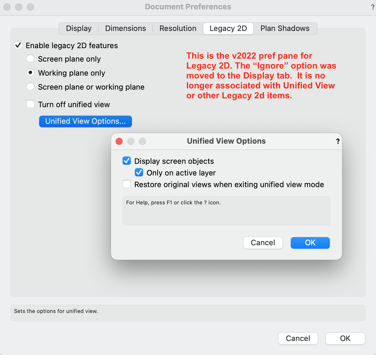
I keep seeing this pref when I don't need it, and have difficulty finding it when I do want it! It might have changed in v2021 (to the Legacy tab, and then changed again in v2022 (to the Display tab)???: -B


-
Also look at your Layer Options in the View Menu or Navigation Palette. HTH -B

-
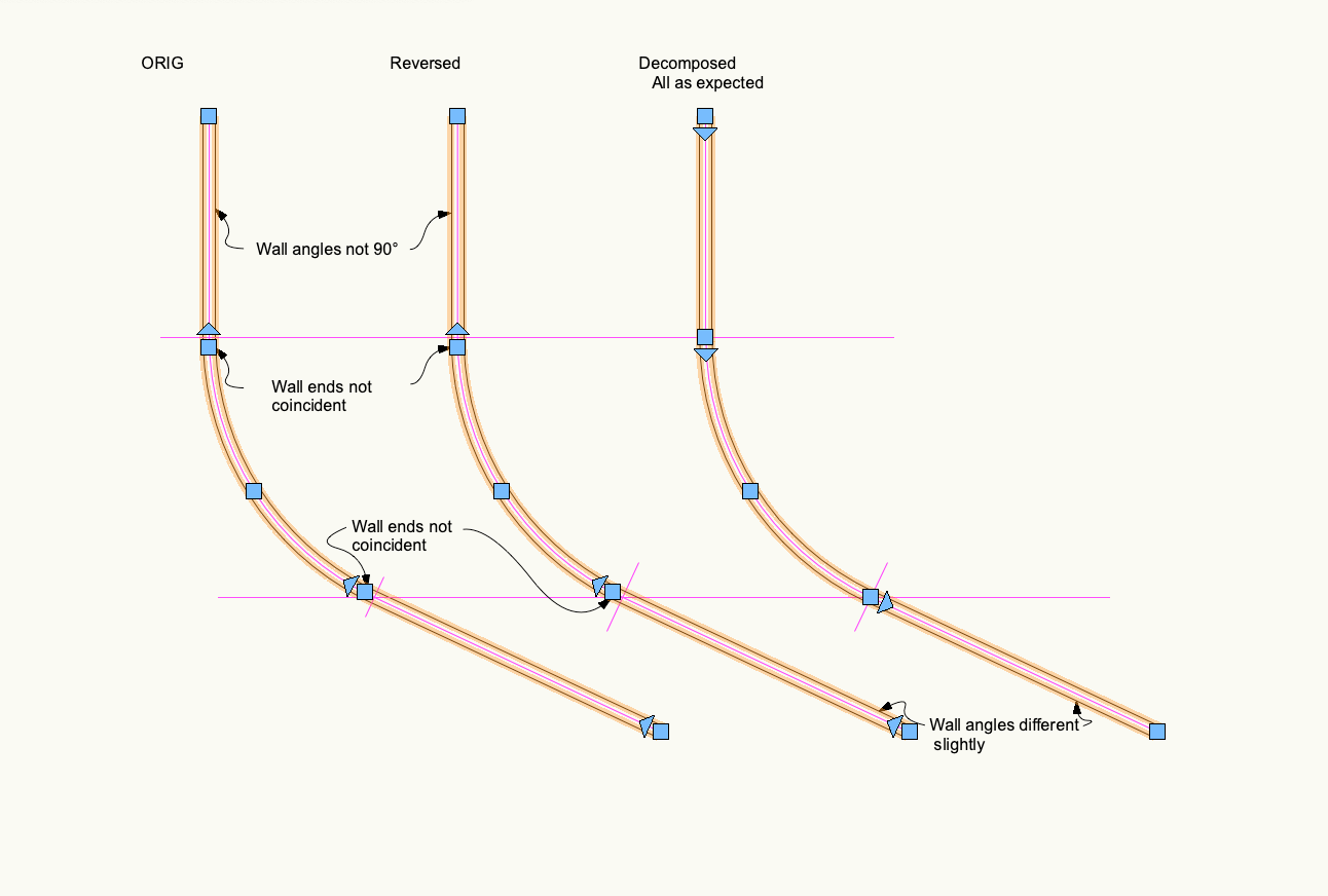
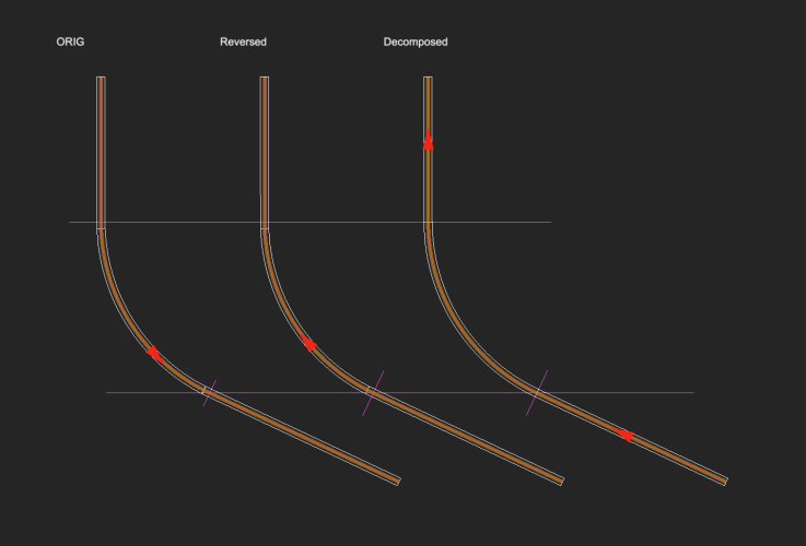
Annnd, add another tangent segment to the source: Note - Wall creation option for Center was chosen here. Right and Left yield same errors. Arc wall is shortened at both ends, wall angle of starting and end straight segments is off axis (vertex moved). Looks like Decompose, then Objects from Shapes is best practice. Walls are as expected. Direction of source poly yields same errors and walls of same direction??? Switched to light background for clarity of the wall directions. Strange that the reversed poly yields same wall direction. -B

-
I reversed the path intentionally to demonstrate the problem and a possible workaround. I had previously discovered through testing that reversing solved the problem , at least for this poly. Although, i think the poly with straight and tangent arc always produces the error in one direction but not the other. Another workaround is to decompose the source poly. Downside is that resulting walls may need edit for consistent direction. In Side 1, I was very surprised to see the straight wall end vertex move, and therefore the wall angle change. The short straight wall at end of the arc is about equal in length to the missing arc part (moved vertex) at start of the curved wall. -B
-
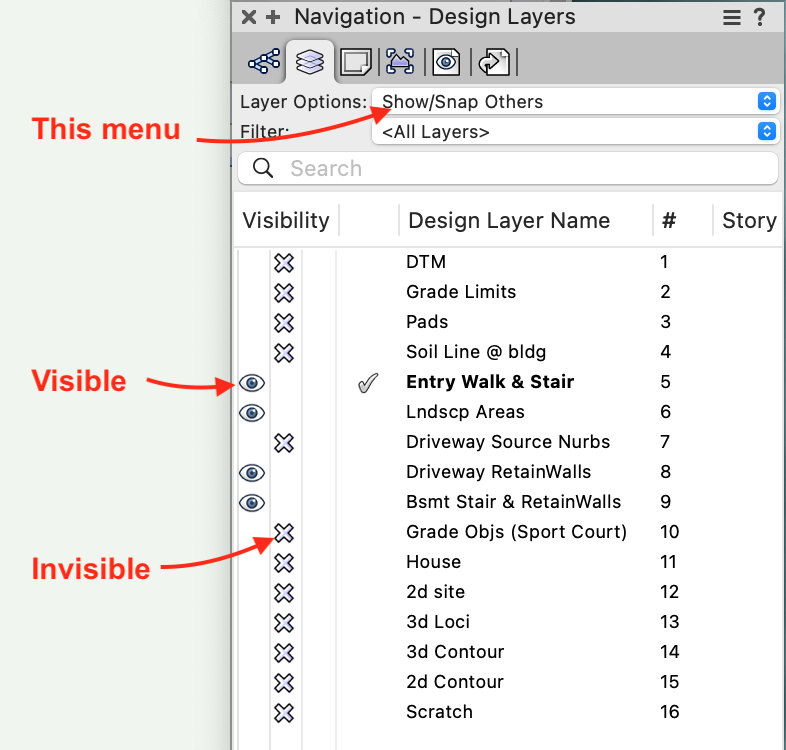
Hi, @Nathan001 - Welcome to the forum! To help with troubleshooting, please create a signature with your vwx version and a bit about your hardware via the pulldown menu under your name - upper right in the forum window. In the menu, choose Account Settings, then Signature. This signature info will show in all your posts. Layer visibilities control depends somewhat on your product. Fundamentals? Landmark? etc The Organization Palette is in all versions. Access it via the Tools Menu>Organization. Open the Design Layer tab and find at left 3 columns for Visibility (Visible,Invisible, Gray). Click in the desired column next to the row of each design layer. Same process in Class tab for class visibility. This palette is comprehensive and therefore big on screen and doesn't minimize. Many users leave it hidden and only call it from the menu when needed. But it can be left open if desired, eg on another screen. Navigation Palette is included in the industry series (Architect, Spotlight, Landmark, Designer) and works about same as the Org Palette. For many users, this palette is normally left open as part of the interface. It can be minimized, too. Is that what you meant by the shortcut on home screen? Read in Help about Saved Views. They save a visibility status for quick access without need to individually switch layers and classes on and off. OK, post back for more help -B
-
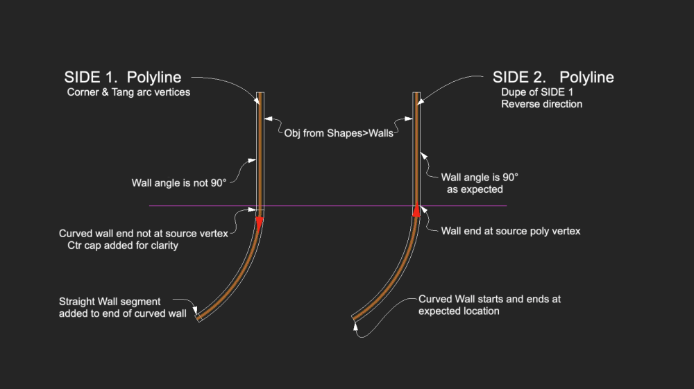
Horsing around with the Create Objects from Shapes >Walls. Source poly (Side 1.) was made with polyline tool: Straight segment on y axis, then Tangent Arc vertices with tangent click on y axis. Side 2. is duplicate, moved over, then direction reversed. The command seems to depend on direction of the source poly. Side 1 funky, Side 2 just right. Known problem/bug? One can delete the walls and reverse the poly(s) and run the command again. Or is there another strategy? Either way, I think the initial direction should not matter. -B
- 4 replies
-
- 1
-

-
- objects from shapes
- walls
- (and 1 more)
-
Should we use Landscape Areas for 'all' hardscapes?
Benson Shaw replied to hollister design Studio's topic in Site Design
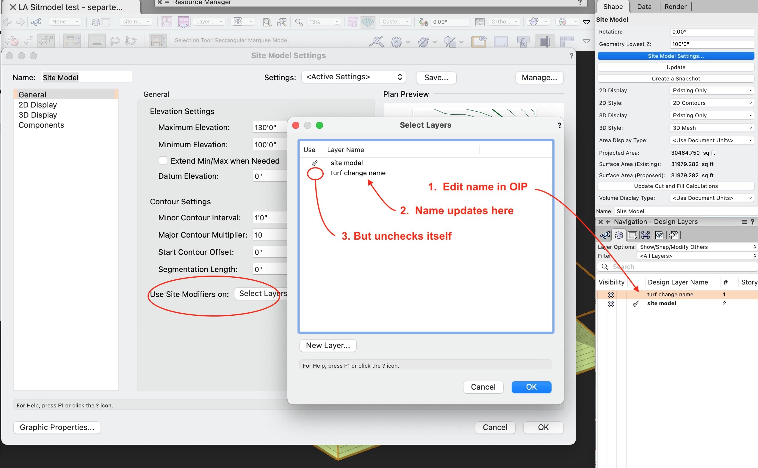
Thanks, once again, @jeff prince! I stand corrected and hope my claim was not misleading to anyone. In my defense - Doh! I sent my LA from DTM layer to an empty layer which was previously designated to modify the DTM via the Select Layers option. Then I changed name of that layer to indicate the LA. Then I tested and found the LA did not modify the DTM. Problem was the new name caused the DTM settings to uncheck that layer in the modifying list. Strangely, the layer name updated in the modifying list, but the designation automatically unchecked. It tripped me up, but I can't decide if this is a problem or a benefit? Seems a little inconsistent. -B
-
Should we use Landscape Areas for 'all' hardscapes?
Benson Shaw replied to hollister design Studio's topic in Site Design
Another consideration for use of Landscape areas instead of slabs or hardscapes. I believe they need to be present on same layer as the site model and located within the extents of the terrain to conform to the terrain. Move the LA away from the terrain, or place on another layer, and the LA reverts to a flattened volume, at Datum height, on the layer plane. Not necessarily a problem, because visibility can be controlled by class of the LA and/or the LA components. But it is different from true site modifiers which can be isolated on separate layers. If there is need to work with the volume shaped by the terrain, then some conversion to solid geometry is necessary. Again, not a failing of vwx, but needs some forethought and strategy. eg. Work with a Duplicate LA. Convert to Group or Ungroup. Result is a Mesh and a group containing the 3d poly perimeter of the LA. -B -
Site - Exclude area within grade limits
Benson Shaw replied to Anders Blomberg's topic in Site Design
The grid of 3d loci seems a good solution although thats a lot of point data. Would a few stakes or grade objects assigned to the Existing also work? I think the Site-DTM-Modifier class (needs a more convenient name, so SDM class?, or Magic class?) only affects the Proposed state which might conflict with or confuse future Proposed site modifiers. Another idea is to add new “existing” conditions to the DTM source data. Would it work to add the soil contact building outlines (the 3d traces sent to surface) as new data via the Rebuild From Source Data function? These would be interpreted as contours with varying elevation. One would need to clip out any contours or other data inside the footprints. -B -
Extrudes only rendering solid from certain angles.
Benson Shaw replied to wclights's question in Troubleshooting
Cannot reproduce the anomalies. 2022SP4. No vwx files open. Several other apps running, but no files open in background. Opened a new vwx 1:1 file, made an extrude from a rectangle near origin, created a cropped SLVP. Rendered Shaded and Final in design layer and sheet layer. Rendered with drawing status in both white background and dark background. Testd VP in 72ppi and 300ppi. DL and SLVP Shaded edges always correct depending on background color. All faces render in Design Layer during active flyover. -B -
Should we use Landscape Areas for 'all' hardscapes?
Benson Shaw replied to hollister design Studio's topic in Site Design
A bit of mystery to me: Creation of the 1st LA in a file containing a Terrain automatically spawns the new class Site>Landscape Area>Spec. 1. Does it have special properties? eg something similar to effects of Site>DTM> Modifier on 3d polys and NURBS curves? 2. What is intent and common use case for this class? eg assign to component materials? 3. What is abbreviation? Specification? Special? So many options! -B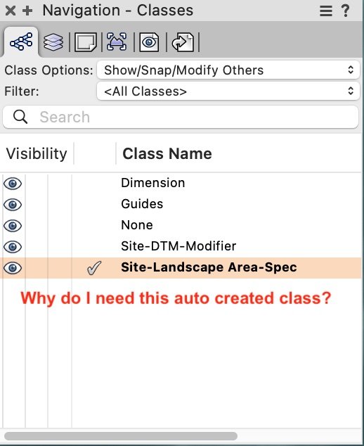
-
Should we use Landscape Areas for 'all' hardscapes?
Benson Shaw replied to hollister design Studio's topic in Site Design
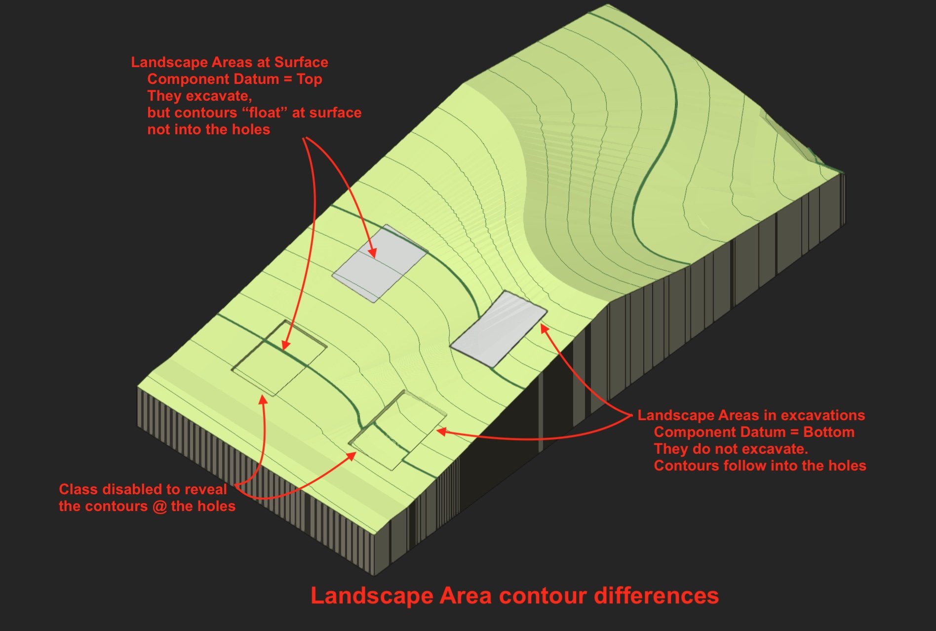
I have explored Landscape areas with components recently. My test terrain is burning! I really prefer using LA in many situations, especially if the perimeter is curved and/or the surface shape is twisted. To paraphrase Douglas Adams narrator in The Hitchhiker's Guide to the Galaxy: Landscape areas are almost, but not quite, entirely unlike Site Modifiers. For example, the LA with component(s) excavates the terrain if the datum is set to Top of the component stack. But if such an LA is then hidden to reveal the excavation, the contours do not flow into the hole. Instead, they float at the implied terrain surface. If there is some desire to show the contours bending into the excavation, then apply site modifiers as needed to sculpt the terrain and place the LA at bottom of the excavation and set the datum to Bottom of the stack. Either way works fine. Which is to say that strategy is in play for many aspects of LA application rather than hard workflow rules. Classing of the components, the container LA, any site mods, etc needs focus to achieve the desired outcome. -B
-
@Marissa Farrell Excellent! Thank you for unraveling that numeric mystery! Also, turns out that the Any Node OIP> eval field is math capable. Keying in the individual multiplications is same as keying in the products: (196*256),(220*256),(196*256) = (50176,56320,50176). Even better, for me anyway, the background math of the Any Node OIP> eval field leaves my 3 sets of parens intact rather than showing the products. This means a different color can be input by amending the 1st term(s). No need to key in the * and the 256 each time. Yay! -B
-
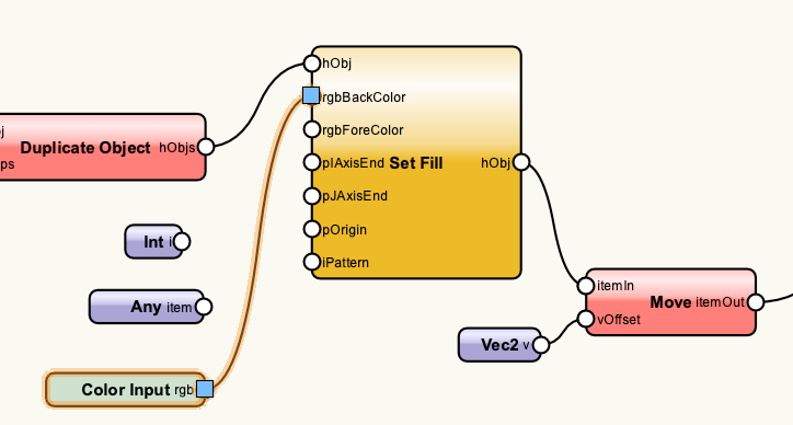
@Antonio Landsberger & @Marissa Farrell Thank you for comments. Any node seems to accept the integer numbers from the Classic Vectorworks Colors chart and return the associated color. That's good, but same as Integer node. Color Input node is great because input is via the attributes palette color selection of the node itself. But if the rgb values are from external source, these nodes do not offer a place for that input. I don't know python, so looked up tuple. For example, Color Chart number 247 (2nd row, pale green) rgb value is 196, 220, 196. So should the tuple be something like 196, 220, 196 or (196,220,196) or ("196","220","196") or ? Is there a node with input port and OIP fields to accept the tuple? What format? parentheses? commas? spaces? quotes? My Mnet produces an object with color fill. How can I assign the fill color via the rgb trio values? Current network uses the Set Fill node with input to the rgbBack port. Other color fill assign process would be fine, too. Thanks -B
-
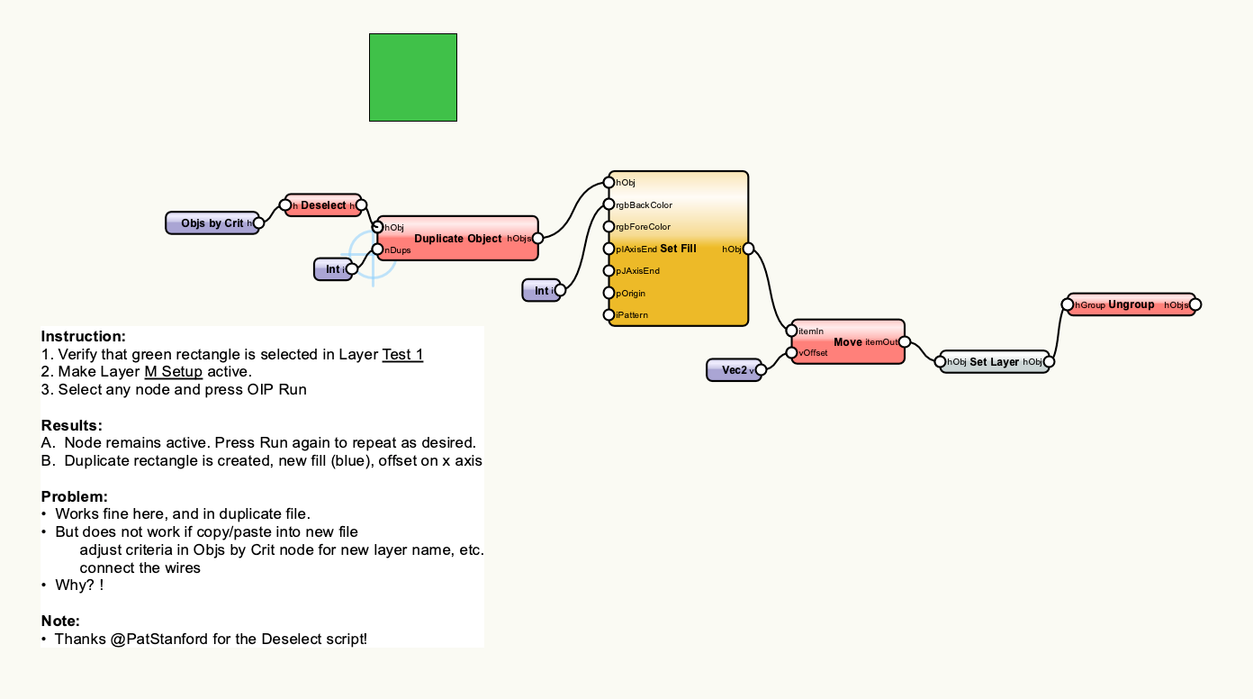
@Marissa Farrell & @Pat Stanford Many thanks for looking at this. I tested in both SP3 636848 and SP3.1 646432. Same result. Something is happening in the paste operation if Marionette classes are not present in the new blank file. The network pastes without wires and, if wires are then manually connected, the network does not work. No blink. Nadda. Also, dissociating then reassigning the classes to the nodes does not resolve the problem. Those nodes seem inoperable. But . . . Now that the classes are present . . . If those pasted nodes are ignored or deleted, and the paste operation is repeated, this second copy of the network includes wires and when the layer parameters are adjusted, the network runs as expected. -B
-
I didn't run into an issue when copy-pasting to a new file. Let's look into this more. Could you try it again? @Marissa Farrell I can reliably recreate the problem. I think is result of order of reproduction. My theory is that the nodes manifest first, then the Marionette classes are formed after. The nodes are not connecting to (recognizing? recognized by?) their classes. Here is the scenario: Create a new blank file. Note that none of of the standard Marionette classes are present. Copy/paste the network into the new blank file. When the network is pasted into the blank file, the nodes are pasted, the classes are automatically formed, but none of the wires are present. Connect the wires and adjust layer designations in the Objs by Crit and Set Layer. Run. Result is a Syntax Error focused on the Objs by Crit node. Solutions: The Marionette classes are now present in the new file. Soooo . . . Delete the network. Paste it again (or copy/paste from original file). The wires are present and the network runs as expected. Or As @Pat Stanford discovered, Wrap the network, copy/paste the wrap to new file. Marionette classes are automatically formed. Unwrap or Edit to adjust the variables (wires are present). Network runs as expected. -B
-
Nice, the wrapper copy/pastes OK. Then unwrap. Thanks for the tip. Buuuuut . . . Goal: Run the network. A new object is created and remains selected. Subsequent run commands create new object from the selected object from previous run. A different outcome if run the wrapper: New object is created and offset as expected, but it is not selected. Even worse if the wrapper is converted to Mobject: The Mojbect disappears and relocates to the same layer as the new object from the network. Sort of expected. I guess the Mojbect is intended to be (and converts to) the thing which is manipulated. In this case, the invisible Mobject can be selected via Edit>Invert Selection. But cannot be selected via marquee. also, it's invisible, so, um, where exactly is it? Also, too bad the Reset script doesn't affect the wrapper. It only works on the Mobject. Oh, well. At least some progress today. -B
-
Excellent, Pat! Many thanks!!! I made it work in a test file and duplicate file (attached). But a syntax error results if all elements are copy/paste into a new blank file (also attached). Any trouble shoot appreciated. -B Deselect&Dupe.vwx Dupe Fail.vwx

-
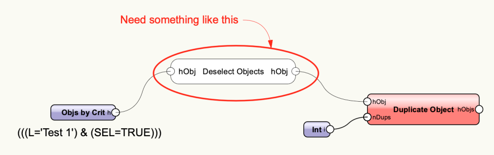
Objs by Crit node can "get" an object, eg by selection status. If that selected object is duplicated via the Duplicate Object node, the result is that both objects are selected. Is there a node that will deselect the original. Or a script that can be put into an Mnode to deselect a selection? Probably best if deselection happens prior to the duplication. -B
-
Here is another thread with similar topic: -B
-
To elaborate on @jeff prince comment: Place a 2d rectangle around the entire site and extrude it to a height that places top surface at or slightly above the water level. Do this in a duplicate file: Site model surface can be used to section the extrude resulting in volume representing the lake water. Copy/paste the water volume object to the project file. This all gets tricky if representing a river or other course of flowing water. Needs to be done in segments of each slope. Extrude is from side based on section along the fall line instead of from layer plane. If representing seasonal or tidal flows, make several separate volumes based on flow data. -B
-
Im not testing this, only speculating. Is there a naming conflict involved? Eg do both the dlvp source file (the house) and the target file (the site) have a same named class or symbol? eg some window component? Vwx would not have unique definition of visibility or attributes for that class. DLVP version requires one status, the target file another status. or were the windows or curved wall flipped and that doesn’t register correctly in the DLVP? Bottom image show a window in the side wall and another standing on the ground in front of the curved wall. no clue about that top of wall. -B
-
I find that Landscape Areas are flat on the layer plane if not associated with a Site Model. If the Texture Bed display option is chosen, the LA can have components above or below the layer plane depending on Datum setting. But still flat. Just a thought: Can you create a simple site model by placing 3d loci or stakes at known or desired grade points? Or based on end points of intended slopes? You seem to have some target grades for hardscapes and LAs. Or if you have survey data - contours or points - start a new file and make a Site Model to start learning. The basics of creating a Site Model are really easy. Modifiers such as Pads and Grades and Hardscapes usually require a surrounding Grade Limits to make sensible grading schemes. Sometimes you want the Grade Limits tight around the modifiers, always at least slightly outboard. Other times grade limits around whole site or big portion of it creates the desired effect. Post here for loads of help getting a Site Model up and running. -B