Benson Shaw
-
Posts
4,317 -
Joined
-
Last visited
Content Type
Profiles
Forums
Events
Articles
Marionette
Store
Everything posted by Benson Shaw
-
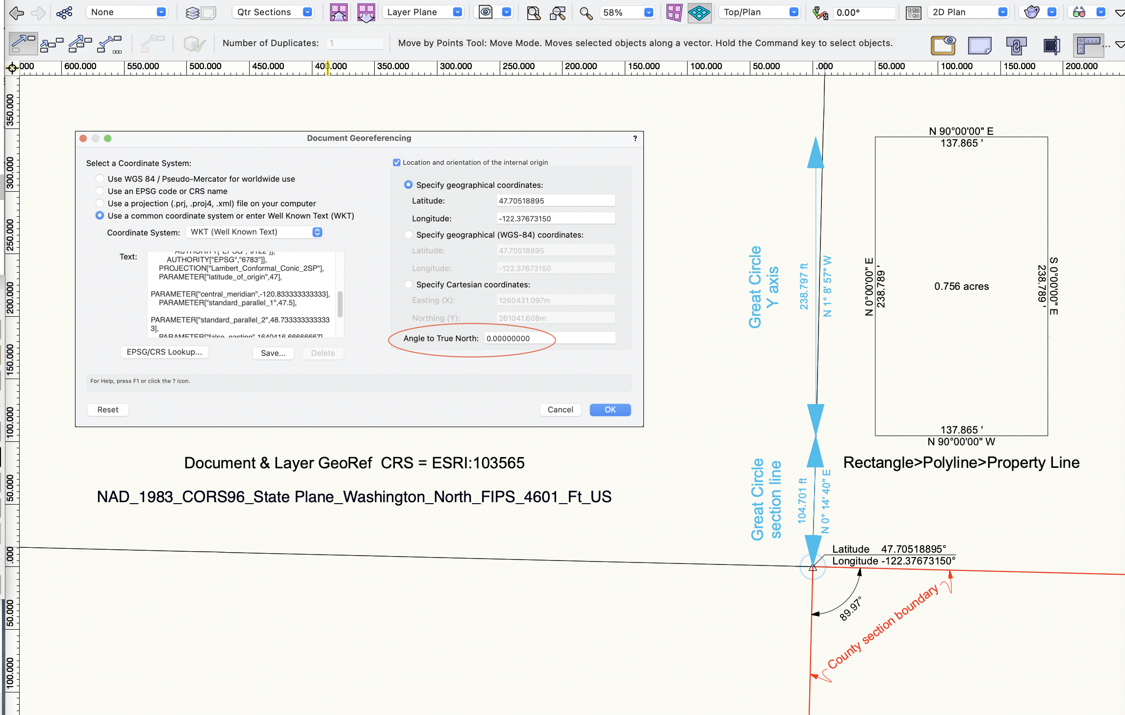
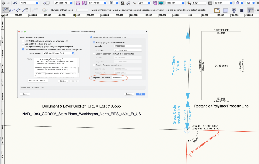
Trying to understand North in georef context. In the example image, the file has a US Washington state plane CRS as noted. County GIS data portal provides the section and quarter section geometry and data. VWX internal origin and user origins are moved to NW corner of the section of interest. This all lines up nicely with the ESRI geoimage and street map. Some comments: TopPlan xy geometry, eg the property line, shows north always parallel to the y axis. I think that's good. Or should it lean? Section lines in USA can adjust to local topography, but idealized version is a square mile with edges on NS and EW. The quarter sections from this township do not georef closely to north. Noted that public maintained GIS data is not presented as highly precise. It's not same as commissioned property survey. The data portals all have warnings that it is more for cartography and not basis for legal or real estate transactions. So, grain of salt on these geometries. Great circle north varies about a degree from y axis at the internal origin. Is there somewhere in the drawing where great circle north is same direction as y axis? eg at the CRS meridian? how to find that? Relocating a great circle east/west (eg drag or move by points) changes its bearing. That makes sense, because the bearing must adjust to maintain the connection to the polar rotation points. So, a few questions: In a survey withp roperty boundary bearings and distances, and CRS/projection notation, is vectorworks xy geometry appropriate, eg the prop line with its bearing notations? What conditions would cause a need to adjust the georef setup angle to true north? Or is this north rotation option sort of a georef version of drawing plan rotation - used for graphic or workflow convenience? I would like to see the great circle tool have editable bearing/distance values. OK, just trying to understand more of the georef features. Thanks for any comment or experience. -B
-
Welcome to the forum! couple things: 1. If not proprietary, isolate the file in a Dbox folder and post here a link for download. Forum folks will try to open and find problems. If proprietary, contact tech support. 2. This or similar message might show up if the file name or location is changed while the file is open. Something to try - Quit Vectorworks, duplicate the problem file on your local drive, move the duplicate (eg to new folder or desktop), change the name of the duplicate file (eg orig_name_test.vwx), launch Vectorworks and try to open the file. Moving or renaming also breaks any references. 3. Add a signature via your forum account settings. Troubleshooting is much easier if our posts show vwx version, and a bit about OS and hardware. -B
-
Not sure if this is issue, but the cutting operation (clip surface) should be performed in Top/Plan. -B
-
.LAZ file coming in to document way out of scale.
Benson Shaw replied to tekbench's topic in Site Design
OK, no apparent improvement v2023. I'm importing NOAA point clouds to vwx georeferenced files. Have tried the LAZ, LAS and both xyz options. Tried with the Ground only and the All options. These point clouds import way too big and nowhere near the file's correct georef location or elevation. I can cut/paste to a properly georefed DTM (eg made from NOAA contours) and then rescale at ≈.305, and move/nudge to make the points sit on the DTM. This is not High Accuracy Reference Network. And how does one apply textures on a point cloud?, eg the aerial or the local map. Thanks, anyone who can unpack this a bit. -B -
Not sure how relevant to Marrionette, but check out vwx Help for Surface from Curves. There are conditions for success involving number of crossings and number of resulting divisions. Kind of arcane, but them’s the rules. As Pat suggests, Loft of one type or another can often work if Surface from Curves fails. Also, fun fact: NURBS curves are never closed in the way that a Polygon is closed. Start and end points may be coincident, but can always be moved apart to demonstrate non closure. I have not tried Loft with Marionette. Can it pick, in correct order, a sequence of “ribs”, and at each rib choose the desired vertex? That would be really cool! -B
-
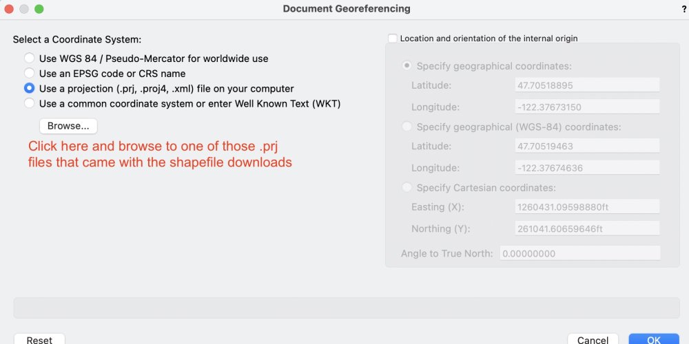
@StatonCohen Some comments from limited experience: 1. The multiple files are just the conditions required for Shapefiles (.shp). GIS software is used to collate data with locational geography. Points and shapes in GIS projects represent social and physical data associated with locations - roads, parks, wells, contours, building outlines, political and property boundaries . . . heart attack incident addresses, flood zones, crop types, etc, etc. Often only one type of feature is included in the shapefile, eg roads, or building outlines, or contours. The shapefile for a particular feature set generates those reference files (.dbf, .proj, .shx, etc). When the shapefile is imported to vwx, info in the support files does different things (someone with more knowledge will explain whether vwx actually needs those other files, or if they are contained in the shp file). Anyway, to be safe, I suggest keep the support files, but make a folder for each group. Name each folder to show the type of feature. More about those support files at the ESRI website https://desktop.arcgis.com/en/arcmap/10.3/manage-data/shapefiles/shapefile-file-extensions.htm. 2. Scale of imported geometry - The shp files from Open Street Map are georeferenced. Georeferencing is a way to reconcile or reduce distortion when boundaries and locations from the spherical surface of earth are mapped to or represented on a flat drawing plane. There are various strategies for this which involve different ways to unwrap the earth's sphere and show smaller areas - Projections and Coordinate Reference Systems (CRS). There are MANY CRSs and projections. The vwx file needs to be georeferenced with same projection or CRS as the shapefile in order for the imported geometry to be "correct". (More about "correct" below.) A georeferenced vwx file is assigned projection and/or a Coordinate Reference System via initial document creation, or, for existing files, via the File>Document Settings>Georeferencing pane. To correct your existing file, I suggest opening that pref pane, select the projection option and browse to one of the prj files. Things already in the drawing may move far away. Zoom to them, then reset the drawing internal origin to a significant point in or near the site in your file. Use the Geo locate tool. Then probably a good idea to also set the User Origin close to your project geometry via Tools menu>Origin>User Origin>Next Click (unless you know a coordinate). Perhaps choose a property corner? Or on the new Internal Origin? Your choice. 3. Lots of GIS info may be derived from aerial photos and algorithms (street edges, building outlines, etc) so can be a bit funky. Or, it may be inaccurate for other reasons. It's not same as an accurate survey. Use at your own risk. This should get you started. Post back as needed -B
-
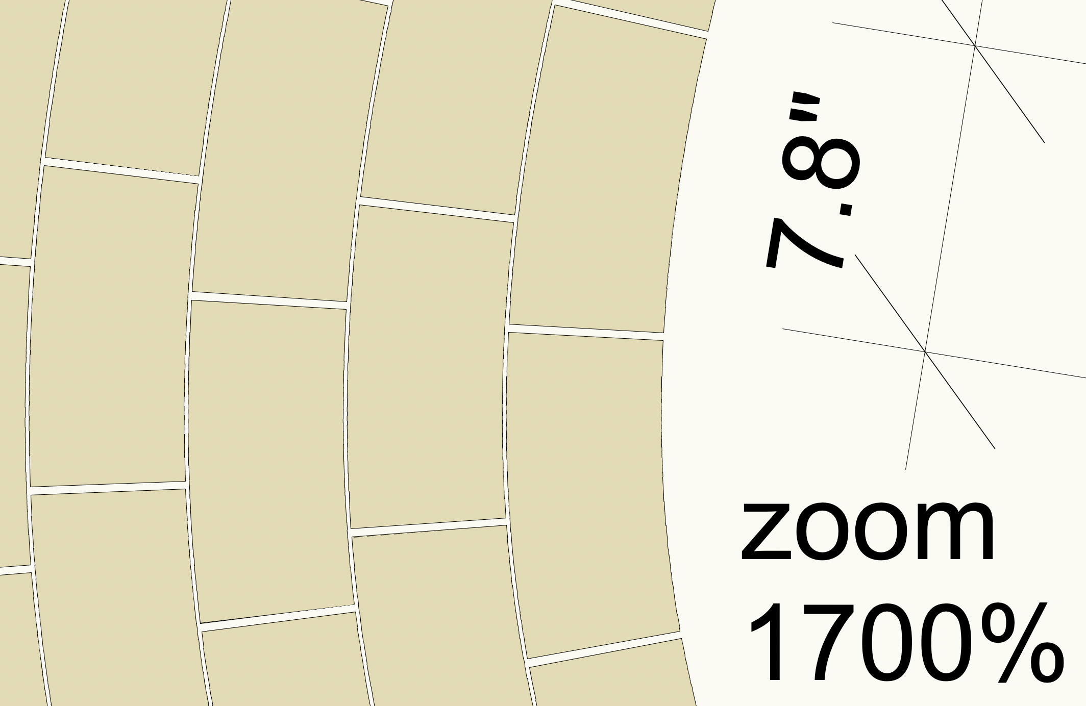
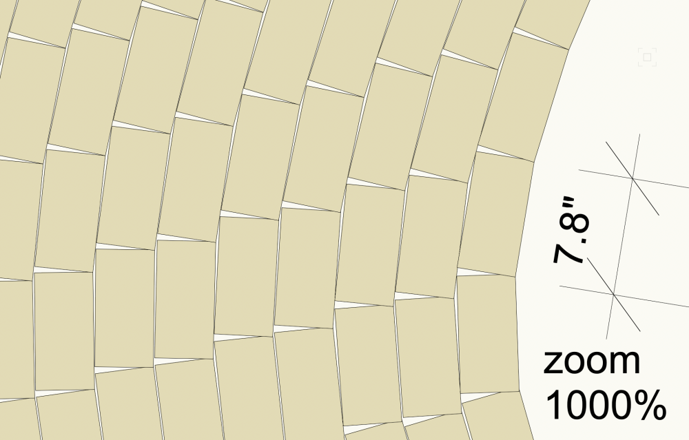
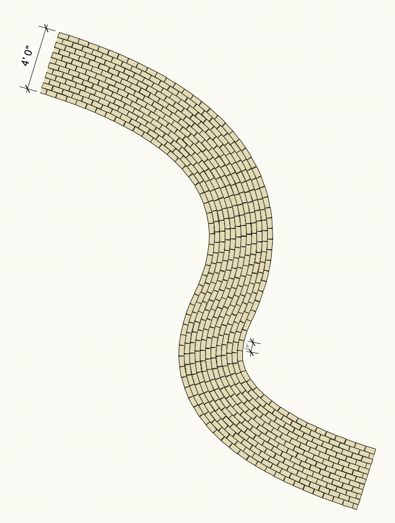
I'm liking this custom line type option. It works well with a closed shape, eg a rectangle. Color and class, and a gap can be established. All these methods give a good impression of pavers arrayed along curves. Actual location/splay/gap of individual pavers in the installed world will likely be different. Examples below show 4" courses. Custom linetype geometry is 7.8"x3.9" rectangle and .2" gap. Zoom plays tricks in the drawing space. Rectangles convert to curvy at higher zoom. -B

-
AHHH, here is line type version. Use the Complex mode in linetype creation panes. -B Pavers LINE TYPE(1).mov
-
@Holly2779 Here is some followup. I cannot find controls for those extra lines. The occur wherever the source poly has a vertex. The paver spacing/coursing resets at each line, so the pattern ends up with some shorties at the line. Perhaps others have a way to control visibility of the lines. I feel like I'm the keeper of Vectorworks Arcane Knowledge (trivia?). I did not invent this, but here is a fun and surprising way into unit pavers with the Parking Along Path command. Works well in 2d. Translation to 3d would probably involve creating and applying an image texture of the entire pavement. Or if a site model is present, and the hardscape is at the surface, convert the pacer linework to 3d polys and Send to Surface. Can be done, but what a pain! Wish there is a direct Vectorworks way to do this: -B Pavers on Curve(3).mov
-
Z axis missing on object to align to working plane
Benson Shaw replied to blunn's question in Troubleshooting
@Tom W. I think OP’s description suggests that the extrude was formed on layer plane, then in front view rotated 90deg. Screenshot looks like rotation is about object center, perhaps via cmdL. If that is the case, then the extrude native botZ is defeated. Or, at least it no longer applies to the layer plane. No clue about that illegal object message. @blunn Could you post a file with that object in position shown? -B -
Z axis missing on object to align to working plane
Benson Shaw replied to blunn's question in Troubleshooting
Or move straight up via drag or MBP. Best to use a Flyover view. I like the second mode of Flyover - click to assign the rotation center. Here's a video demo of both methods. -B Move to z=o(sm).mov -
Z axis missing on object to align to working plane
Benson Shaw replied to blunn's question in Troubleshooting
@Pat Stanford Is this a texture orientation question? I think intent is to move the bottom plane of the extrude to z=0 if so . . . @blunn Sorry for late response. Hope you already resolved this. Forum us usually quicker. There are lots of ways to move things in 3d. Here is one: Put drawing in Top Plan view (Menu Bar, Active View Menu). This makes the Layer Plane active (it's the default Working Plane). Or, without changing the active view, verify that Active Plane is Layer Plane (Menu Bar, Active Layer Menu). Draw a rectangle or other 2d shape. eg draw the outline of portion of your set where bottom of extrude will touch. This shape will exist at z=0. If needed, use the Flyover tool to skew the view so you can see corners of the extrude and corners of the 2d shape. With Select tool, click the extrude at a bottom corner or edge and drag to intended edge or corner of the 2d shape. Or select the Extrude, engage the Move by Points tool (1st mode, no duplicates will be made), then click a corner/edge of extrude bottom, then click the 2d shape. Either way, extrude will move in 3d so that bottom of extrude is at z=0. If needed, reposition the extrude via Drag or Move by Points and/or use the Rotate tool. Might be helpful to do this move and rotate in Top/Plan view. Note - your screenshots show a narrow drawing area with Menu Bar dropdowns showing dots rather than text which can make it difficult to know your drawing's status (view, active plane, active layer, etc). Hover to see the menu labels. As you learn Vectorworks, this will become second nature. Good luck! Post back if more help needed. -B
-
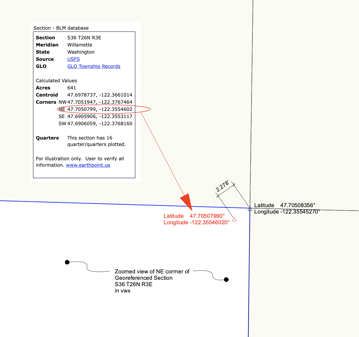
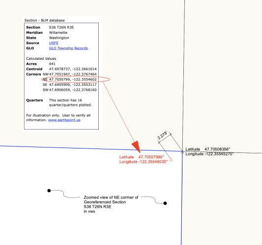
@jeff prince Many thanks for looking and for verification! After checking your file and boiling a bit in my fine kettle of fish, I tried first the repair function in vwx installer (no fix), then, finally, the most obvious: a system reboot. (Duh) Shape files now import as expected! Yay! This is just me exploring georef. No liability with clients. Onward to compare/verify lat/long of corners of section 36 with other sources. I found values at Earthpoint (associated with Google Earth), but coordinates do not match the georeffed corners in vwx. NE corner is out by a couple feet which isn't horrible (.04%) over the mile width of the section. But, I thought it would be closer or spot on because assumed BLM and County data derived from same PLSS survey. Guess not. Or maybe Earthpoint uses other projection/CRS. Anyway, thanks again. -B -B
-
Attached zip contains 475kb folder with shapefile and associated files describing PLSS quarter section boundaries for Township 26 in King County, Washington, USA. File was acquired as download from the county GIS portal (free if you want to fetch for yourself). The .shp file does not load into my VWX2023. Strangely, this shp file loads properly into Qgis. I also have a folder with same named files acquired from same county data hub in 2020. Thatv shp file loads as expected into vwx2023. Newer shapefile import produces this error regarding the .shx support file. Note that the shx file is named twice - extension in caps and extension in lower case: CPLErr( 3 ), err_no( 4 ) Unable to open /Users/bensonshaw/Desktop/PLS QtrSec Twnshp26/Public_Land_Survey_Quarter_Sections_-_3_county_area___plss_qtr_area.shx or /Users/bensonshaw/Desktop/PLS QtrSec Twnshp26/Public_Land_Survey_Quarter_Sections_-_3_county_area___plss_qtr_area.SHX. Set SHAPE_RESTORE_SHX config option to YES to restore or create it. No clue how to make the suggested correction. Is this problem with my installation of vwx2023? MacOS 12.6 (Monterey)? the county data hub? Can anyone make it import to vwx2023? try v2022 or earlier? Here's the county GIS data standard: Projection: State Plane* Zone: 5601 (Washington State Plane North; FIPS Zone 4601) Datum: HPGN Units: feet *Technically, State Plane is a coordinate system, not a projection. Any comment appreciated -B PLS QtrSec Twnshp26.zip
-
@Holly2779 glad you found that! We (forum) should have mentioned this, too. It’s usually fine to communicate idea of paver courses following a curve. But does have some fail points if detail is needed. My uses often require placement of individual pavers. In this hardscape feature, pavers are not separate rectangles (I’m assuming intended design is unit pavers), but rather are the blank spaces surrounded by curved course lines and the end joint lines. Joints have no width, so cannot indicate splays or possible large infill areas along sharp curves. Blah blah blah. Often none of that is of concern. If others do not post, I will try to remember how to remove those construction joints and report in a later post. -B
-
v2023 Bug? Revolve w/ Rail cursor preview highlight
Benson Shaw posted a question in Troubleshooting
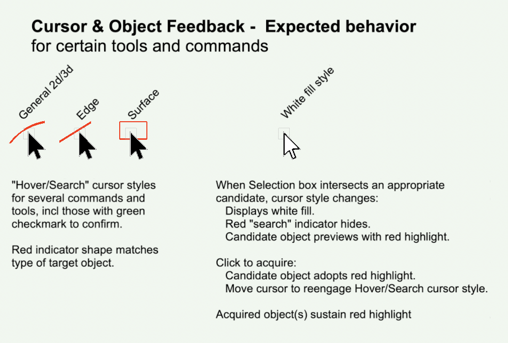
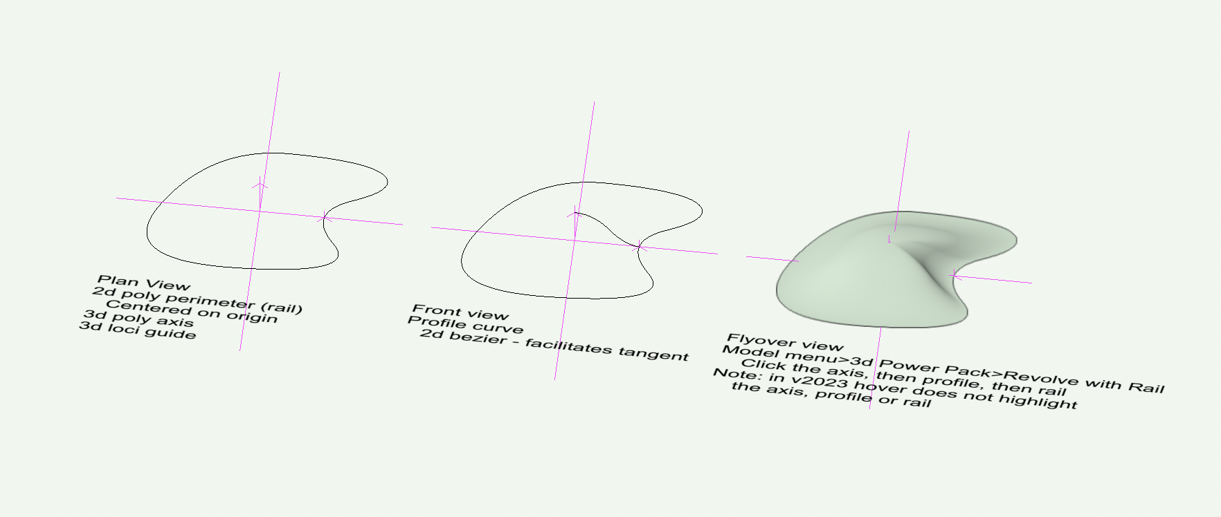
Three steps to effect the Revolve with Rail command - select Axis, then Profile, then Rail. At each step, the cursor should trigger a pre selection highlight of the candidate object, but does not. This is a feedback issue. If several objects are close to the cursor during the hover, the cursor changes from black style to white style to indicate a nearby appropriate candidate. But, which one? Pre selection highlight would indicate which one. Most (all?) other multi step tools and commands, including those with the green checkmark to complete (Loft, Extract, Fillet, etc) produce a preacquisition highlight. Other aspects of the Revolve with Rail process seem to be working as expected. The candidate object does highlight red when acquired with a click, and the command does create the solid object as expected. I think the is a v2023 issue. Anyway, I cannot remember noticing in earlier versions. -B Rev w:Rail 3.1mb.mov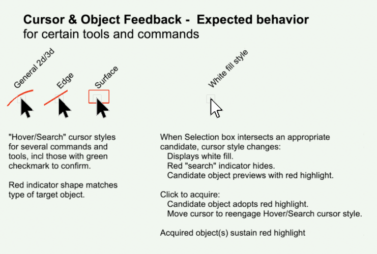
-
@Holly2779 hardscape with border might work for the parking area. Or try the Duplicate Along Path command in the Edit menu. Just make a copy of the relevant edge (the path) and a rectangle or other paver shape (the object to duplicate). Select both and run the command. If paver has incorrect orientation, undo, rotate the paver 90deg, then DAP again. I, too, would love to see the @Tamsin Slatter screenshots. Can moderator facilitate regen? Old thread, so maybe images are lost. For extended discussion see also: -B
-
Check if those texture beds can be selected in both exist and proposed. Maybe they were placed in both states and deleted in only one? Or if the beds were placed on layers other than the dtm, check deleted from those layers. Sometimes the wire frame view offers easier selection of site mods. but definitely update the dtm. -B
-
@zoomer good idea. Some finesse is required, but might work. They can accept component strata. My limited experiments with those berm mounds proved them less than useful. The initial numeric setup through the falloffs and percents is difficult to predict outcome. I think the perimeter shape is hard to control, too, if not impossible. And I found no predictable way to undo or edit. Probably more experience would help. -B
-
Was it Revolve with Rail? -B

-
threaded rod drawing only 2D, need 3D
Benson Shaw replied to Chuck McQuinn's question in Troubleshooting
I like the Set Screw mode of the Fastener Tool (top option in the Fastener Toolset). After creation, object can be adjusted for diam/thread and length in OIP. Down side is that the drive end will show the "head" socket/slot. All of these options are a bit render heavy with the threads shown, but no prob if only a few. Some savings if Ungroup, which converts it to Generic solid, but then no more adjust possible through the OIP. Make a long set screw and use Split to cut desired segments. These auto convert to Generic Solids, but can be split again as desired for length. They have sharp ends. -B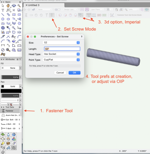
-
Mesh can be edited with the Select Tool by marquee selecting one or several vertices, then dragging the selection in 3d. I believe that in v2022 and prior, the drag preview shows only the selected vertices moving to the target. ln v2023, the drag preview of selected vertices moves the entire object. When drag is released, the selected vertices stay at target and the rest of the object returns to original position. So, the mesh edits, but the live preview is confusing. Not shown in the video - sometimes, the edit does not succeed and the entire object moves to the target location. This might be problem with initial drag position of cursor? Known bug? -B Mesh Edit Bug 6.8.mov
-
@bcd Most excellent to find a treasure chest at end of tunnel! (Or maybe it’s just full of stuff from my closet) -B
-
Original stakes can be accessed. Suggest experiment with this in a duplicate file so the process and results can be tested. Select the Site Model. Near bottom of OIP click Recreate from Source Data. Depending on zoom and view angle, It might be necessary to Select All, then Zoom to Selection. Deselect All. The low stakes should be discernible in Front or any side other view. Adjust z of any errant stakes, then exit the Edit window. -B
- 1 reply
-
- 1
-

-
place custom symbol with a single click
Benson Shaw replied to yasin2ray's question in Troubleshooting
More similar workarounds - Place the first with dbl click symbol insertion. For the next one(s), Move by Points, with 1 duplicate. Or Duplicate in Place any instance already on the drawing then drag or Move by Points (no dupes). Or make a stack of multiple instances or a swarm (Duplicate Array? Move by Points w/ many dupes?) in some convenient location and just grab/drag one when needed. Delete any extras later. Agree would be better if single click for symbols needing no rotation. But I would want this to be smart behavior, maybe with a warning, rather than needing to toggle modes for rotate/not rotate. Otherwise could be a tripping hazard (for me anyway) - Insert with the tool, expect to need the rotation click, make the rotation click, thereby unintentionally insert another, delete the new one . . . -B