spettitt
-
Posts
330 -
Joined
-
Last visited
Content Type
Profiles
Forums
Events
Articles
Marionette
Store
Everything posted by spettitt
-
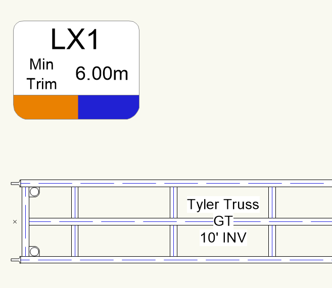
It's this cell on the bottom of our truss tags, which need to re-colour based on the Position field of a truss object (we don't use hanging positions). The object would need to move the class of this cell to the named class matching the Position value of the tagged truss.
-
There does seem to be some auto-assignment going on yes, but I can't reproduce cable types being overwritten when a device moves. If I change or remove a cable type, it remains if I move the device. It seems like it notices what cable type you use for a given signal type and tries to place future circuits using it. Can you screenshot what you mean by the cable type symbol?
-
I'm just scoping out an idea to see if I want to throw some proper hours at it or not. We use data tags to tag all of our trusses with their Position name, trim height and a colour. The colour is currently done by data vis, but as mentioned in other threads, I need to communicate the colour externally via script and data vis is behind a wall, so data vis needs to be replaced by class colours. Vectorworks lacks the AutoCAD functionality of 'ByLayer', whereby the contents of a symbol (or data tag) can inherit attributes from whatever class(layer) their container instance is placed on. This means I need a DT style for every Position name, with the contents on different classes. People could name their trusses anything, so I then need a one-shot cleanup script that gets unique position names, makes classes for any that don't exist, then duplicates DT styles for each one and reclasses the contents, then goes through any DTs placed on the drawing and re-assigns them to the right DT style. I think it would work, but it's not particularly slick. So, I wondered about making a parametric object whereby it looks and functions like the data tag - having an association to a truss object, but being able to reclass it's filled polyline geometry to whatever class name matches the Position value. It wouldn't really even need any OIP controls, just the easiest way to create an association to a picked truss. Just wondered if anyone thought this sounded possible or a terrible idea...
-
That got it, thanks. Hadn't noticed that one. I found I needed the 1167 reset after it, but together they get the job done. Cheers
-
Thanks @klinzey, understood.
-
I'm trying to get a system where data tags can auto-colour themselves based the Position Name of the truss they are tagging, via class attributes of the contents in the tag. I have truss tag styles of LX1, LX2. My script should find the Position of the truss (ie LX1) and swap to the correct data tag style. The new style will have contents of class Lighting-Position-LX1. The script below works as far as correctly showing the new Style Name in the Style: selector of the Data Tag OIP. But it won't redraw itself until I double click and Edit Tag Layout. I feel like I've thrown the kitchen sink at it for reset options, but it visually displays the old tag. Any ideas for other reset options please? (I don't want to use data vis, as the reason for class colours is the ability to communicate our Position Colours outside of Vectorworks via script in both directions, and Data Vis is out of bounds to scripts at the moment, I believe) def resetbits(h): vs.ResetObject(h) vs.ResetBBox(h) def processtags(h): htruss, kind, value = vs.GetAssociation(h, 0) posname = vs.GetRField(htruss, 'TrussItem', 'PositionName') newtagname = f'{posname} Truss Tag' vs.SetPluginStyle(h, newtagname) profilegroup = vs.GetCustomObjectProfileGroup(h) vs.ForEachObjectInList(resetbits,0,1, profilegroup) vs.ResetBBox(h) vs.ReDraw() vs.ResetObject(h) vs.SetObjectVariableBoolean(h, 1167, True) vs.DT_UpdateTaggedTags(h) vs.ForEachObject(processtags, "PON = 'Data Tag'") vs.ReDrawAll()
-
I wrote a Python script that can parse the XML and get the available modes and their channels, so this may be the way forward. It would be slicker if I could get them from the GDTF in the file though, as I'm transporting the data to a non-Vectorworks user who might not have the GDTF (and probably doesn't even know what one is)
-
Excellent, thanks for this.
-
I'm trying to gain the ability to change the GDTF mode of a fixture via script. I have a GDTF loaded and assigned to fixtures in my drawing. I would like for my script to be able to get all of the available modes in the GDTF file so the user can pick. I am unsure how to locate this data for anything but the currently selected mode. Also, I can SetRField of the GDTF Mode and Num Channels no problem - but there is no validation. I can assign a mode name and footprint that doesn't exist. I'm trying to think about how I could use something more akin to a primary key than just 'Manufacturer' and 'Model' strings. I can see in the XML inside the GDTF that an Ayrton Cobra is fixture type E4F96447-2A9B-47B8-B7DA-BC4AFB17F276, but I'm unsure how to get this in Vectorworks. I can see hidden records of: __GDTFFixtureTypeID as 'Lighting Device'.'GDTF Fixture Type ID' __GDTFFixtureModeCustomID as 'Lighting Device'.'GDTF Fixture Custom ID' but these both just return '0'. Any advice appreciated.
-
Thanks guys. I'm planning this for an office environment with maybe 15-20 users of varied skill, some of which have opposable thumbs and good discipline, and others may be unintentionally rogue with taking copies of their project's master Vectorworks file from the server. We're not using Project Sharing (yet) for a few reasons, and our current server and file management works well for us, I'm just trying to consider the edge cases where user has saved a copy locally on their machine without knowing. Like you say, the fact that a stored UUID carries to a duplicate will help most users though, in the case of backups/corruption etc. I like the idea of a hidden record - for this and other things. @JBenghiat is there anything to know with making a record hidden, please? From what I can see it involves a double underscore, but I don't know if that's a cause or a symptom. Thank you
-
Thanks. In this application in our office, I want to make sure it's the very same file and not a duplicate. Even if it ends up needing that ability to be reimported to a duplicate, maybe for a corruption or something, it will need a strong warning to say its not the original file. I'll have a think how else I could do it. Cheers
-
I've written a plugin that collects a bunch of object data and pushes it out as a database, where a non-Vectorworks user can edit it. It can then be re-imported and the relevant objects get updated. I'd like the plugin to get the unique ID of the VW file and store it in the outgoing database, so if someone imports it back to the wrong VW file, it can say "This isn't the Vectorworks file your database was exported from. Give yourself a talking-to'. I've had a look through the function reference and I can get the VW file name, but not really a primary key for it. It might be a GetObjectUUID, but I don't know how to get the handle of the file itself (if there is such a thing). Thanks!
-
The Other Symbols dropdown only applies to symbols - the plugin should export all 3D primitives not within symbols regardless of the settings in the dialog. I believe it's because the plugin doesn't yet support Extrude Along Path. I'd just convert it to a generic solid and that should work.
-
Thanks Scott, that makes sense and seems a good system. I think I'm aiming for it to be more automatic for data integrity, so I might have a go at a scripted solution.
-
I'm having a go with Cable Paths. For various reasons, I'm not going to be putting individual cables down them, just drawing the routes of feeders and which trusses they run to. I can see that the Spotlight version of the tool has the ability to highlight a target truss in red, where the ConnectCAD one doesn't. Once this association is made, where can it be seen/accessed? I'd just like to get the Position Name of the truss (which isn't in a hanging position) that I've landed the cable path on at each end - maybe so I can report it in worksheets, data tags and the like. I know I can manually enter the ID and Location, but that's open to error. If this needs to be scripted then fair enough, but it would be nice to not need another script.
-
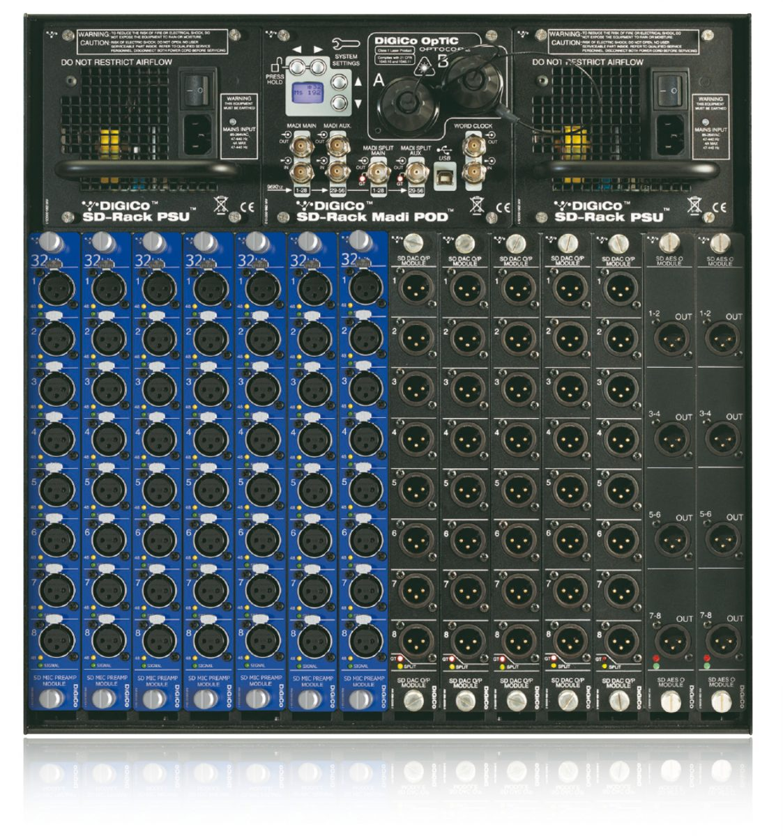
There are all sorts of things at play here, but I will try and help with what I know. To clarify - when you say you save things as ConnectCAD Symbols, you mean schematic Devices as symbols right? We do the same, saving each Device as a symbol in our workgroup rather than using Device Builder. When you say 'at run time' - presuming you mean the 'Create Equipment' command? This command has a checkbox at the bottom. If checked, CC will take the Make and Model of each schematic device, look at the Device CSV in your Workgroup ConnectCAD Database folder to find a symbol name, and search the Entertainment folder of your workgroup library for any Symbols names that match. This CSV is the same one that the Device Builder stores to, but in the workgroup location rather than the equivalent User location. It's only looking at three columns - Make, Model, Symbol. I highly recommend downloading a program called ModernCSV as it lets you edit the CSV in an Excel-like interface, meaning you don't need to worry about mucking up the syntax of the CSV. So even though you're storing your devices as symbols, you need to add a row in this CSV for each symbol that needs to be looked up, but you only need to fill in three columns. If Create Equipment can't find a matching symbol in the workgroup, it will draw the default. If it can, it will use that. Now, the symbol it finds can be one of two things - a standard black-text symbol which is just geometry, or a pre-formatted equipment item stored as a red-text plug-in object Symbol, with the black-text symbol nested inside. If I'm doing the latter, I'll call the red symbol DiGiCo SD-Rack and the nested symbol zDiGiCo SD-Rack, with the z reminding me it's nested. For things without adaptor slots and without things that stick out of the front panel, I don't bother making the red symbol and just leave the black symbol as DiGiCo SD-Rack. The Create Equipment command will find them find and assign them to the Equipment Items as they are created. The gotcha here is that it assumes all of your rack equipment has a front panel of 3mm and no thicker. It takes the symbol geometry, finds the front of the bounding box, takes 3mm backwards and aligns that with the rack rails. If you have a large connector on the front panel that is something that requires coordination for clearances (large multipin connectors, 16A CEE inputs/outputs, amplifiers with large handles/bump bars to name a few), this is a problem, as it buries the equipment far back. Our red symbols help this as well, as we can pre-set the location of the symbol forwards in the library, which is respected by the Create Equipment command. If you need adapter slots, these can be pre-set inside this stored red symbol. Overall, this process works nicely apart from one thing, which is that red symbols will arrive in the drawing showing the desired nested symbol and adapter slots, and the default generated rack equipment item, which among other things, often ends up z-fighting. The user needs to either delete the default generated rack equipment geometry, or untick use symbol for the opposite. I think the guys might be going to have a look at fixing that.
-

How to place gear on the back side of the rack
spettitt replied to Vegas James's topic in ConnectCAD
A few ways: Move to some sort of angled view of the rear (isometric rear right for example) and then drag the item you want to the rear rails. As you hover over, it should highlight the position that it will be snapping to. Or select an item and find the Mounting option in the OIP (object info palette) and change it to rear. -
I believe that is accurate at the moment. Data Vis for GLs is a feature that has been much requested already, so hopefully it will be a thing in the future.
-
I don't know how much you've come across Vectorworks terminology yet, but it would be more typical to colour by Class than Layer. In short - Classes in Vectorworks usually equate to Layers in other CAD platforms. Layers in VW mean something a little different. Classes are the 'what' (door, window, moving light, followspot) and layers are the 'where' (floor package, LX1, LX2, or however you want to structure it). It is possible to colour objects in the drawing by Layer, but colouring by Class (i.e. classification of object type) is the default that things are set up for, really. However, all of my fixtures have hard-coded colours in our library, so I don't have a lot of experience with colouring fixtures specifically by class. I have a feeling that in the case of Lighting Devices from the standard library, colouring by class might be challenging, as I think most of the content is set to high-level classes, i.e. 'Moving Light', 'Conventional' etc, as opposed to specific types of fixture (strobe, beam, batten, profile etc). I would have a go with data visualisation, which is a tool for dynamically recolouring objects based on whatever data you choose. In this case, you'll probably want to use the Instrument Type parameter to colour them. - Make a new Data Vis - Object Criteria will be Type = Lighting Device - Display Criteria will be Parameter - Lighting Device - Instrument Type - This should present you with a list of the fixture types in your show. - Add fill colours as desired, and remember to tick 'Apply' to the rows you want it to affect. (data vis is very powerful as you can make several of them and turn them on/off as needed - try making one that greys out patched fixtures and shows unpatched fixtures in red - very useful) If you do use this, you'll need to select your 'Fixture Type Colours' Data Vis for any viewports you want it to print in as well. I'm sure others will be along shortly to explain other ways of doing it. Personally, I just have hard coded colours in our library symbols, but that doesn't mean it's the right thing for you.
-
I might have a bash at a script for this when I get a sec, I'd be interested in it as well.
-
Thanks Nikolay, will PM you a file.
-
From what I can tell, Adapter Slot objects only work in the 3D component of an Equipment Item, and not in a symbol that may be displayed with 'Use Symbol'. But, when running Create Equipment, it seems to generate a fresh one rather than using the Equipment Items we have pre-configured in Workgroup/ConnectCAD/Equipment Item. We have this Equipment Item library so that someone can start a project from layouts and generate the schematic later (with CDFW) or start with schematics and Create Equipment. I would like to pre-set the adaptor slots in the Equipment Item, but at the moment, I can't see a way to do this. We work with loads of equipment like this, and having to re-draw 14 tall adapter slots each use is quite tedious. Please let me know if I'm missing something, or I'll log a request. Thanks

-
Adapters always build to the right - so when you edit it, the content should always be on the right hand side of the origin. Then when you dock it to a left-facing socket (usually an input), CC knows the orientation of the socket is the opposite to the right-facing way the adapter is made, and will flip it. This means you can have one adapter symbol that works on either side of a device without requiring two different definitions. Mostly useful for SFPs, which can then dock to SFP sockets on either side of a switch device.
- 1 reply
-
- 2
-

-
Changing layers shouldn't do that. Accidentally running 'Ungroup' on the circuit probably would do?
-
Hey @Nikolay Zhelyazkov, Thank you for this, sorry for the slow response, been off for a few days. I will have another go in light of what you say. Thanks Simon