Scott C. Parker
-
Posts
691 -
Joined
-
Last visited
Everything posted by Scott C. Parker
-
COFFEE BREAK - CUSTOM DATA TAGS https://university.vectorworks.net/mod/overview/view.php?id=3018 COFFEE BREAK - SPOTLIGHT: DATA TAGS FOR ENTERTAINMENT https://university.vectorworks.net/mod/overview/view.php?id=2494
-
Here's a coffee break for custom data tags. https://university.vectorworks.net/mod/overview/view.php?id=3018
-
Likely, yes. Users can create just about any layout they wish. We have an entire forum page for users to share custom data tags. The first few posts have videos on making data tags. https://forum.vectorworks.net/index.php?/forum/186-data-tags/ The easiest way to make a custom one is to duplicate an existing tag and make adjustments. Here's a coffee break showing custom data tags. https://university.vectorworks.net/mod/overview/view.php?id=3018
-
The new tool does not do data yet. Yes, you can use both the VW cable tools alongside Autoplot's cable tools. The main differences are VW can do 3D, power calcs, and is Braceworks aware. Autoplot can do both power and data, but in 2D only. Adding data is on the list, but we want to get all the bugs out of VW's cable tools. We're almost there.
-

Cable Inventory by Location/Position-Worksheet
Scott C. Parker replied to KevinF1973's topic in Entertainment
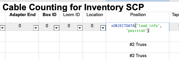
"Location" is not automatically inserted. However, "Position" should report the position name from your positions. To grab the position from the load info and place in a worksheet, try adding this: =OBJECTDATA('load info', 'position')
-
Automatic Numbering to Working with Cable Tools Break Outs
Scott C. Parker replied to KevinF1973's topic in Entertainment
Yes, it's a bug. Pressing Shift pauses autonumbering. If you place without the shift, you'll be good to go. We're working on a solution. -
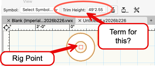
Hello All, I admit that the term "Trim Height" for the house rigging point object always gives me pause. For me, the term "Trim Height" refers to the objects I'm flying, not the height of the pick point, eye bolt, beam, loft block, ceiling, crane, or any other object my baskets or top hooks are attached to. This field sets the height of a house rigging point to which a hoist or bridle's top hook or basket is attached. If you have a preference, what term would you use instead of "Trim Height" shown here?
-
Start here.
-
24V systems & consumers within Cable tools / ConnectCAD
Scott C. Parker replied to tspilman's topic in Entertainment
Hi Tim, Can you build a simple test file to play with? Working in a vwx file can make figuring this stuff out easier. Important question: What kind of documentation are you looking to create? Are you doing a hard-wired installation (ConnectCAD) or a performance-type temporary event using distros, breakouts, cables, and lights (Spotlight Cable Tools)? As for power calcs, I would say it's fully implemented, but may have a few omissions and a few bugs persist. Have you watched my coffee breaks on these? https://university.vectorworks.net/course/view.php?id=3622 https://university.vectorworks.net/course/view.php?id=3692 I made another video showing the improvements to daisy-chaining lights with pass-throughs and using two-fers that is going to be posted soon. I'll add a link when it posts. -
24V systems & consumers within Cable tools / ConnectCAD
Scott C. Parker replied to tspilman's topic in Entertainment
Hi Tim, Very interesting questions. My comments relate to Spotlight Cable Tools and not ConnectCAD directly. Where is the power supply/transformer that supplies the 24VDC power? Does each fixture have a transformer? Or, are you plugging them all into a 24VDC power supply? Yes, you offer more info... Is this set to AC or DC? If DC, are you supplying power to ten 24V lights wired in series? This reminds me of color scroller power supplies. In this type of case, you are correct in your #1 example. We would use the wattage draw of the PSU, rather than that of the downstream devices, for power calculations. Therefore, we would report the 500W PSU as a single 500W consumer, without needing to know how many devices it supplies power to. This could work, but... I've not tested it. We're not currently calculating Amps at all. So, the voltage is also not currently a factor, except for some voltage drop calculations. That's another topic. We're reporting on overall wattage/power. As such, I'm thinking out loud now. Without testing this yet, I would determine how many watts the 24V lights will draw from the system and set them accordingly. Then, build a custom PSU distro or breakout to serve them. This PSU distro will report on the overall wattage being used and allow the upstream devices to see how many Watts are being supplied. The PSU distributer will have the proper four-pin connectors between the outputs and the 24V lights, ensuring accurate cable reports. The input connector of the PSU can be specified as whatever connector you need to patch to the upstream power supply distribution. The bot is correct. -
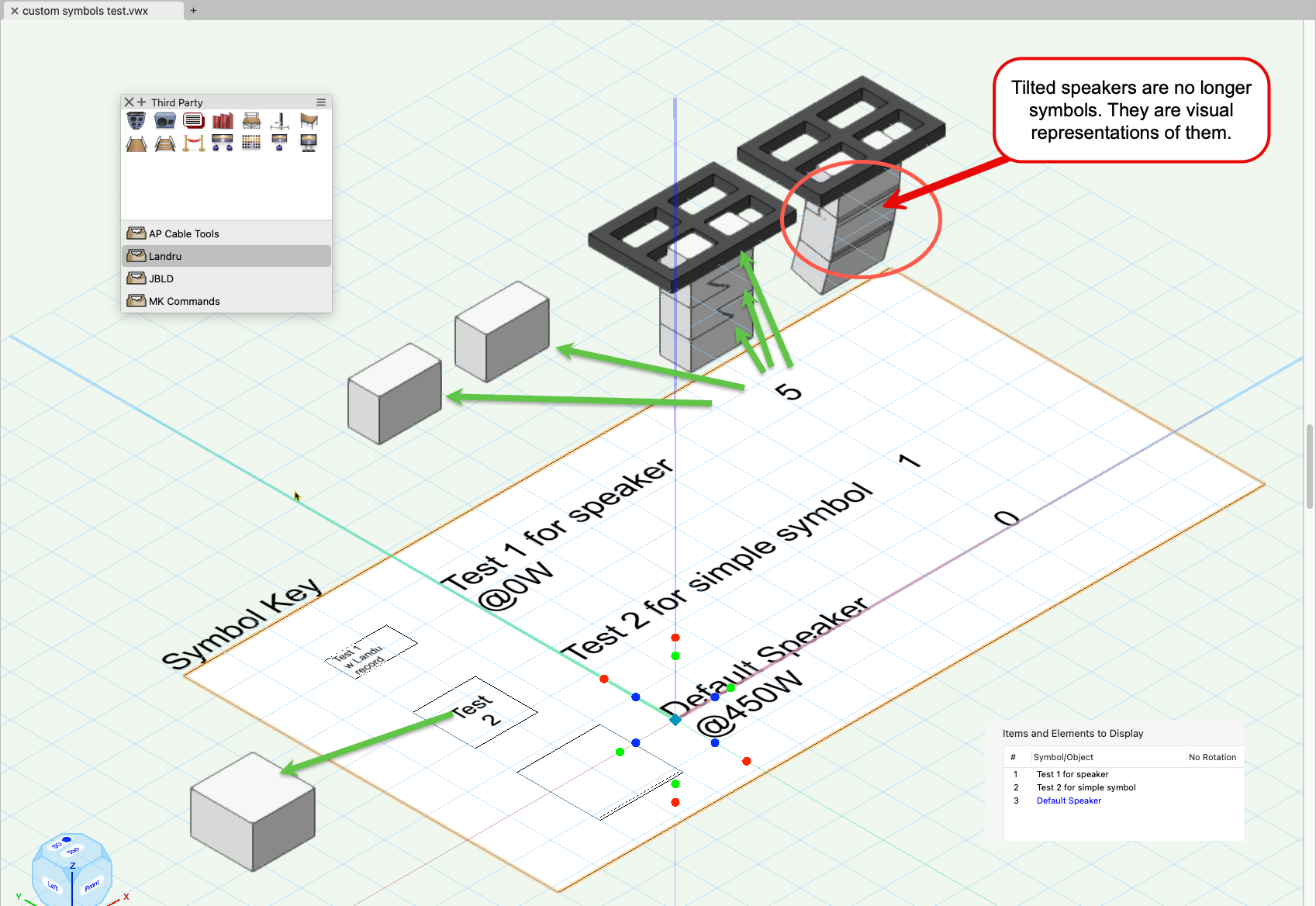
If the PIOs you're using are from third-party developers, the current summary tool can see the symbols when the PIO places actual symbols. However, when the PIO places a visual representation of the symbol, i.e., a parametric object version of the symbol, the summary key is not able to see it yet. In this example, I have five speakers placed as symbols and three drawn as visual versions of the speaker symbols used. Why? When the speakers in the second speaker array are tilted, the PIO draws a parametric object representation of the selected symbol. In this particular case, the speakers are placed with the Landru speaker tools, and I selected actual symbols for placement. If I had used the Library version of speakers, no symbols would be used, and they would not be available to the summary key. Here's this file to play with. custom symbols test.vwx

-
Would you please post a sample file with one of your hoist symbols so we can take a look?
-
How to Show Braceworks Rotational Influence Info?
Scott C. Parker replied to Chris J Clarke's topic in Braceworks
hmmm. We're not showing an overload warning when there is no overload. You can adjust the sensitivity via the Braceworks preferences dialog, allowing you to trigger an overload warning.
-
The current build of 2025 is the most current version of the Spotlight Equip Summary Key. We're working on various improvements, but I do not have a timeline at the moment. I encourage users to share what features they'd like to see so we can add them to our wish list.
-
@Joe Golden ENT Sorry, I need more info to know what you're asking. The summary key pulls in most Spotlight plug-in objects. Do you have a sample file to share? A list of which PIOs you are trying to include? Thanks, Scott
-
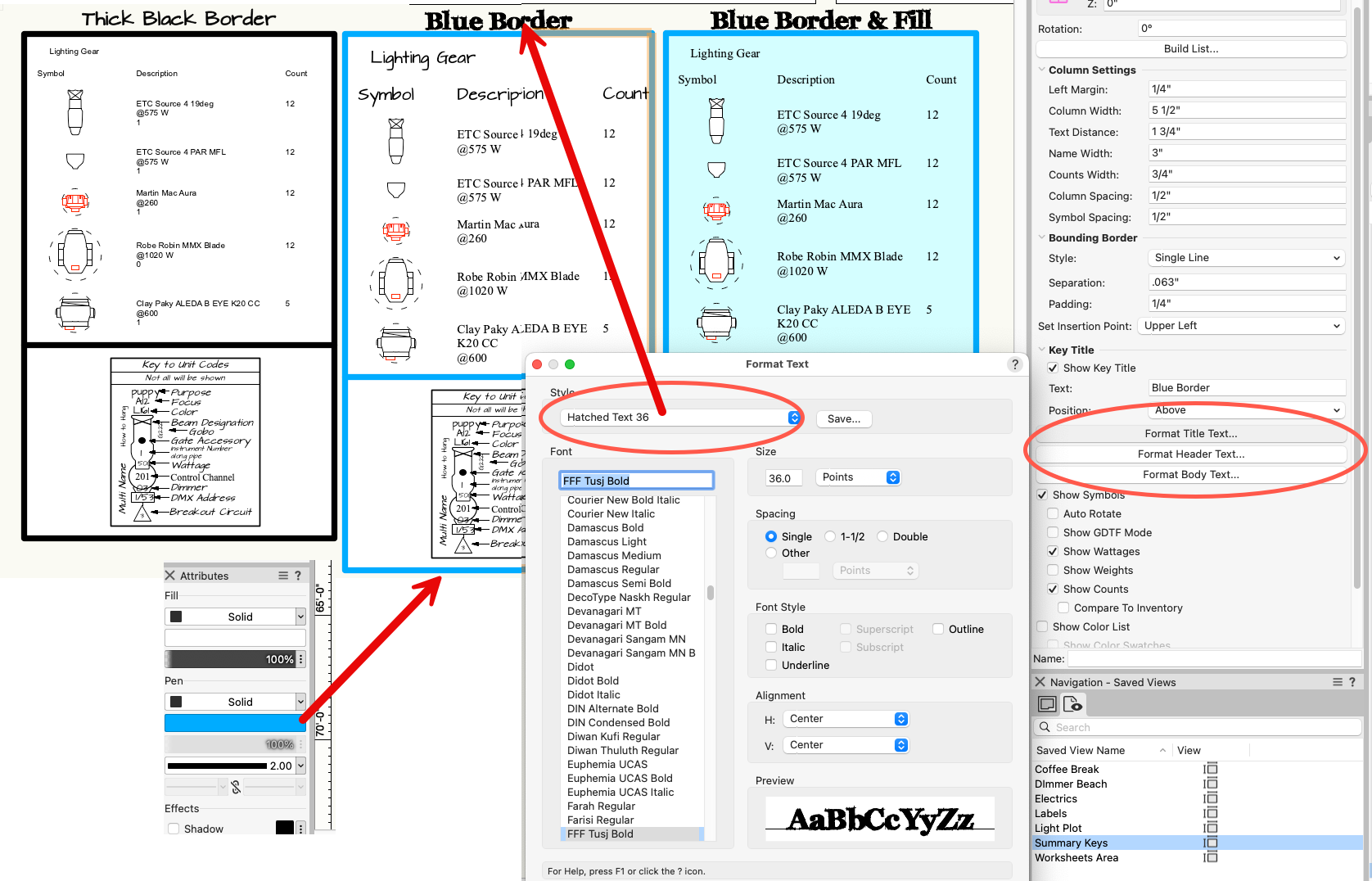
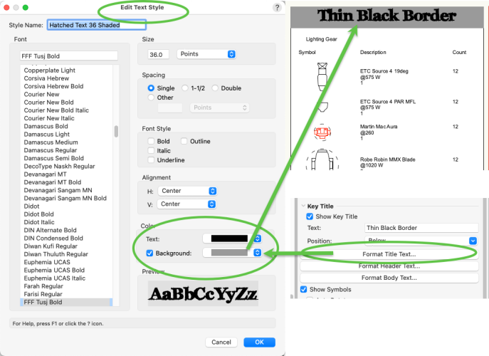
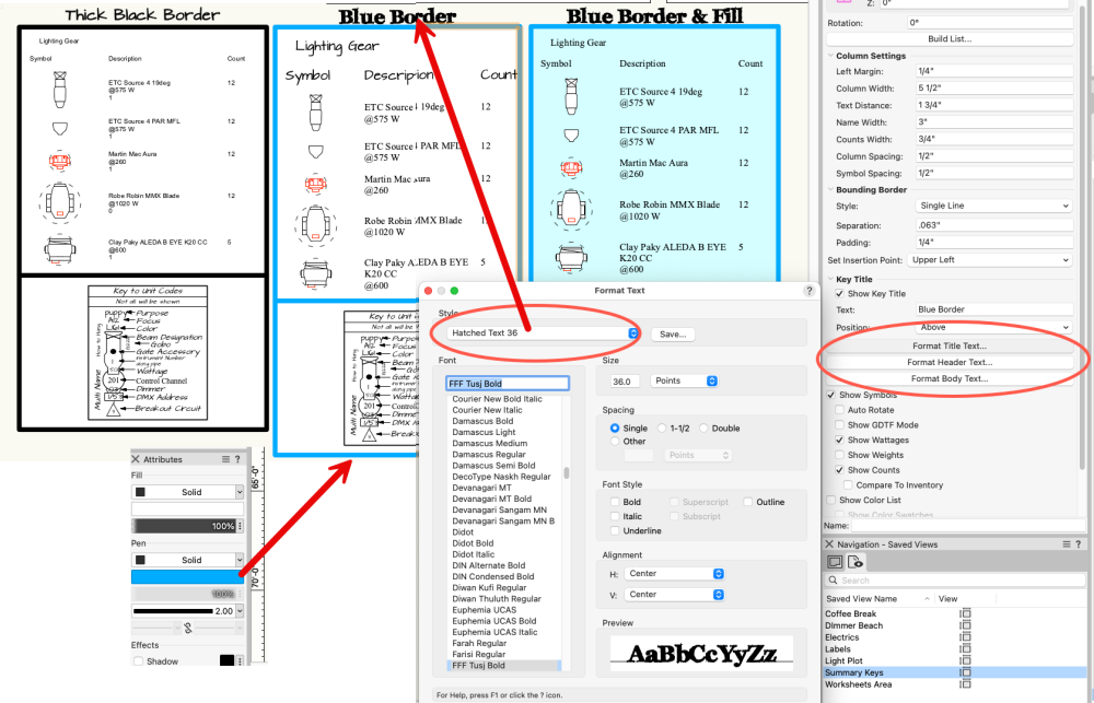
The options I show are in the Edit Text Style box via the Resource Manager. https://app-help.vectorworks.net/2025/eng/VW2025_Guide/Text/Using_text_styles.htm?rhmapfs=true#CSH_2414
-
Yes, but it's inconsistent. I'll report a bug. Place the background shade in the text style and assign it to the title text format. The bug I found is that the background reverts when the key is refreshed. I think it's a stacking order thing.
-
I can't help with the rounded corners, but, for the colors, here's a workflow. Assign Attributes to the Spotlight Equip Summary Key for colors. They will change the colors of the box and the text. To change the text back to black, use the three Format ... Text buttons to assign text styles as you wish. These will override the line attributes to follow the colors/styles used in the saved text style. Once you have the three text styles assigned, you can duplicate the summary key and assign new line colors without overriding the text assignments. I will add an enhancement request to add a rounded corner option to the Bounding Border for future consideration.
-
replace truss symbol converted into hanging position
Scott C. Parker replied to Tomas Lohin's topic in Entertainment
No worries. Sometimes, VW objects are connected in mysterious ways. -
replace truss symbol converted into hanging position
Scott C. Parker replied to Tomas Lohin's topic in Entertainment
Once you are inside the hanging position, you can then follow the normal method up replacing truss in a truss system. It's explained here: https://app-help.vectorworks.net/2025/eng/VW2025_Guide/Braceworks/Replacing truss_type.htm?rhmapfs=true#CSH_1852 Here's a quick guide.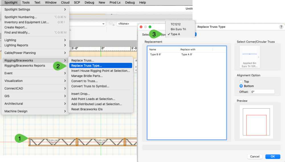
-
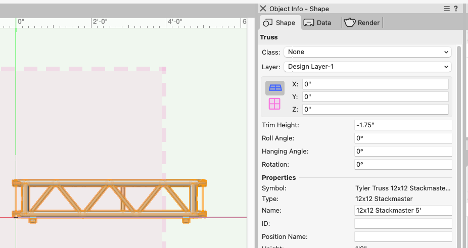
I'm not seeing an issue with your file. I'm on a Mac at the moment. What build of VW are you running? You'll find the build number in the About window. The trim at -1.75" is based on the feet of the truss.
-
please post a sample file so we can see how you have things set up.
-
replace truss symbol converted into hanging position
Scott C. Parker replied to Tomas Lohin's topic in Entertainment
Double-click on the hanging position to get inside the hanging position. Then, you can edit the truss directly. Once done, exit the edit window, and your truss should be good to go. -
Lights snapping to truss when settings are off.
Scott C. Parker replied to Kal-El's topic in Entertainment
What happens when you copy and paste the items you're working with into a new blank drawing? If it keeps happening in a new drawing, please post a copy of the file for testing. -
Please post a file so we can take a look.