btgroves
Member-
Posts
22 -
Joined
-
Last visited
Reputation
3 NeutralPersonal Information
-
Location
United States
Recent Profile Visitors
The recent visitors block is disabled and is not being shown to other users.
-
Hello All, I ran into what I think could possibly be a bug this morning, I have a drawing with a number of Layout Room areas and I used the Create Equipment command to get my schematic devices and place them into a layout room but the room data field is not auto-updating if I drag them into or out of this layout room. Oddly enough if I select my schematic devices and pre-fill the layout room name into the room field prior to running the Create Equipment command this is not an issue, it places them into the layout room and I can drag them into a different one or out of the existing layout room and the field auto updates as normal. Anyone else experiencing this issue?
-
Correct tool for termination / connectors in-line of a connected Circuit?
btgroves replied to btgroves's topic in ConnectCAD
@Thomas_ That is definitely an option, if this venue had an already available patchbay like that we would definitely make use of it, but this is just a DSP and Control upgrade to an existing system and we're trying to keep the cost low for the customer as much as possible. We're also trying to avoid a lot of "re-work" on the integration side. I ended up using the "Term Panel" tool and just deleted the Display Tag field, screenshot below...Still not sure if this would be considered the "right" tool to use but it gets the point across, curious to hear if others have other ideas. -
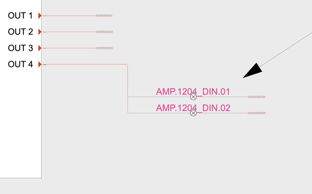
Hello all, we have a situation where we want to provide an physical bypass for a large PA in the rare case there was a DSP failure, I understand there are many ways to do this but we'd like to terminate connectors in-line between devices such that if the DSP fails or is having issues the user could go and physically bypass this gear. I would love to figure out a way to draw this schematically for our integrators in the field but I'm struggling with what tool may be the correct tool to use for this? I've tried using the Adapter Tool but those have to be associated with a circuit, possibly a jackfield could work but it's not really the right use of that tool either, any ideas anyone? Below is an example of what I'm looking for...
-
Our team has expanded into utilizing project sharing a lot more lately and we are running into a bug which seems to affect the scaling of only ConnectCAD circuits. I will complete some ConnectCAD work and my co-worker will open their working file and make sure to refresh with the Project Server copy, in their open working file the ConnectCAD circuits appear as shown below. Has anyone experienced this before or have a resolution?
-
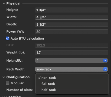
Feature Request: 1/3 & 1/4 Rack Width Options for ConnectCAD Devices?
btgroves replied to btgroves's topic in ConnectCAD
@Conrad Preen I will admit I wasn't as educated on these options for using a "Rack Frame" device, I've spent some time working with this, I do realize this is not considered an "Equipment Item" this is a primary reason I was requesting the options in the HeightRU field. We have a few reports that run on Equipment Item Records and Sort by Equipment Rack/Drop Point Records, since these Rack Frame devices they don't show up in our custom reports but we certainly could adjust the criteria to also find these items. Helpful information, thank you for the suggestions! -
Connector Panel Tool, OIP, Edit Device Array Bug? (Visbility)
btgroves replied to btgroves's topic in ConnectCAD
Thank you! @Nikolay Zhelyazkov -
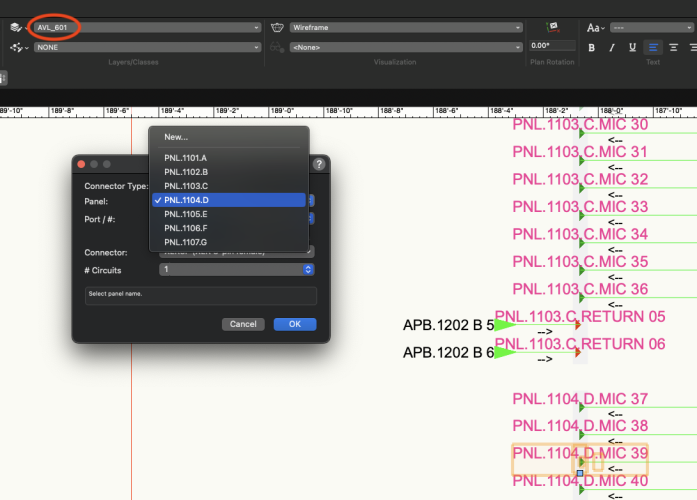
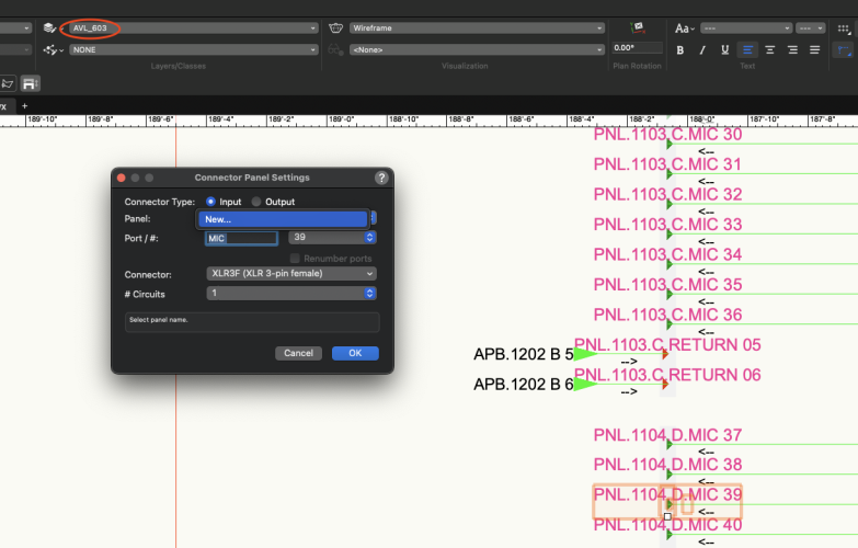
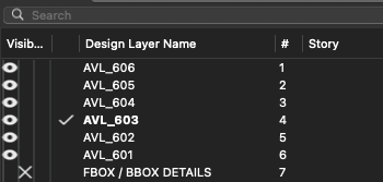
Hello all, I just updated to SP7 this morning, noticed something that may have been happening for a while but I just discovered it... We layout our line drawings within ConnectCAD with a standard viewport scale / sizing, because of this we have unique design layers for each viewport that will ultimately end up on its own sheet. We also do this for the unique Cable Arrow visibility that is automatic when drawing a circuit across Design Layers. I created 5 Panels using the Connector Panel tool, they only show up in the selection drop down box for "Edit Device Array" if I'm actively on that Design Layer, regardless if I have the visibility on in the OIP on the right. If I navigate to a different layer, they no longer appear in the drop-down menu At one point, I was encountering the same issue just while using the Connector Panel tool, but I've since quit and re-launched VWX and can't seem to replicate that issue. Screenshots below for reference.
-
Worksheet Showing a Device's Active Circuits and Un-Connected Sockets?
btgroves replied to btgroves's topic in ConnectCAD
@Conrad Preen and @Pat Stanford Is there a Vectorworks resource that covers complex worksheet creation with step-by-step, video, or long-form teaching on this topic? I do understand the basics of Criteria and Functions but I've only ever been able to successfully create somewhat simple custom worksheets like I showed above with a Criteria looking at a layer and a specific single device record. After looking at the Edit Report dialog in the Device Connections Report a lot of these functions and syntax seem somewhat advanced, and I'm struggling to find content offering help. We do have a need to create custom worksheets and reports for our organization and I would like to do some more advanced report and worksheet creation more like what is contained in the Device Connections Report but with our own formatting and filtering, instead of a very extensive report on the entire drawing like what exists in the Device Connections Report. Any support you all could offer would be greatly appreciated. -
@Conrad Preen I can certainly send you this file although I believe some of these bugs could be related to a separate post I made and I've been messaging with Nikolay Zhelyazkov about. This issue I was experiencing seems to have been resolved when I applied a Fill to the following classes CC-Rack3D-Graphics-LeftPanel CC-Rack3D-Graphics-RightPanel CC-Rack3D-Graphics-TopPanel CC-Rack3D-Graphics-Posts CC-Rack3D-Ruler CC-Rack3D-Text-Name
-
I've spent quite a bit of time building worksheets for our organizations needs with all the different types of ConnectCAD data but I'm having difficulty building a worksheet that will show connected circuits and the associated data but also un-connected circuits? Basically our installers would prefer to see a 1-to-1 table including circuits as well as that devices unconnected sockets. I have a feeling that Data Manager is a tool that can be used to create a record I could possibly pull the relevant data from both the Device Record and Circuiting Record and incorporate data from both records into a custom one of my own. Anybody have experience with this? I've attached a screenshot with what I'm experiencing, as you can see there is a skip from Input 15 to Input 19.
-
Yet another bug in ConnectCAD 2024... I have a file with seven rack elevations that were already built, I opened this file in 2024 to make edits. All the rack elevations already built, showed up correctly, but it seems the "Equipment Item" records are no longer associated with the Equipment Items in the updated 3D Racks. This also causes the new "Make Rack Equipment Worksheet" to not populate with any data whatsoever. To test this I deleted two equipment items that were in the 3D Rack that had been converted, I used Layout > Create Equipment to re-create these two deleted items, then dragged and mounted then into the same 3D Rack. After doing this these two items showed up in the "Make Rack Equipment Worksheet" and any other worksheets we'd created to look for the "Equipment Item" record associated with this specific Rack ID. I can post screenshots if necessary, or send over a file if needed, can we please get some traction on this? This seems to be a significant issue with upgrading existing 2023 files...
-
spettitt, This original issue was resolved with a quit and re-launch of VWX 2024, but today I have experienced the same issue when opening a file that was created in 2023 and I'm regenerating the Rack Elevations using the new features. I cannot seem to resolve this issue with a re-launch like my file above, my viewport settings were initially created with Hidden Line although out organization uses color coding on equipment for indications, so I have to adjust these to be Background Render: Shaded Polygon, Foreground Render: Hidden Line. Any help would be appreciated, currently the only fix is to create filled objects or text boxes to make this viewport readable.
-
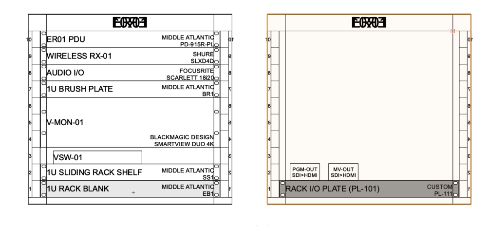
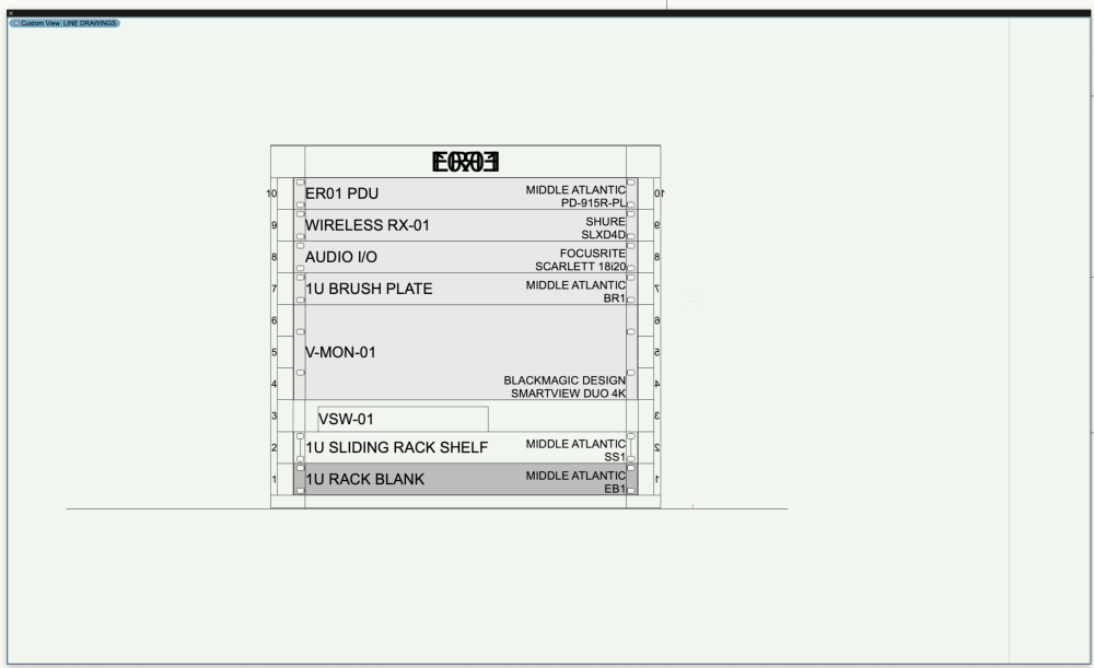
I have created a simple 4-Post Rack, 10U, from scratch, loaded my equipment, when I use any of the following commands "Edit Front of Rack" "Edit Rear of Rack" or "Create Rack Elevation" It shows both forward and reversed text for the Rack ID and Rulers. There does not appear to be any class or way to turn off the inverted text. Any solutions here? It seems I will just have to manually draw in text boxes or shapes with fills to solve this? It seems that these new rack features have been released without full bug testing, this is somewhat frustrating because there is usually a relatively long time between service pack releases. Can there be a hotfix released to help address the number of bugs in ConnectCAD specifically? I have attached a screenshot below to show this...


