tk_
-
Posts
25 -
Joined
-
Last visited
-

ConnectCAD - How to create your own connector graphic styles ?
tk_ replied to Enzo Vernusse's topic in ConnectCAD
I have tried before to create my own Label Styles by duplicating an existing set in the zNested Symbols but cannot get them to populate in the "Label Style" dropdown of the OIP -
@spettitt I like you last idea the best, the device that doesn't look like one approach, I am in a similar boat as we often use network cable to split off various signals, like a DMX sneak snake or the audio equivalent (Radial Catapult box or sound tools cat box). I would be interested to know how you pull the record data into the cable field or is that just a linked text field that looks the same. Thank you
-
yeh yeh, we already do project sharing. I am talking more about linking devices to spotlight objects
-
I am curious about the feasibility and method of linking two sets of records in a manner similar to a pivot table. Frequently, several of us collaborate on distinct aspects of a project. While one team designs a studio in 3D, places lighting fixtures, and generates documentation in a spotlight-focused approach, I create a schematic of the signal flow using ConnectCad. I wonder if, by naming my lighting device in ConnectCad the same as the spotlight fixture in another file, it would be possible to import the patch information and display it in a linked field?
-
could you group them?
-
Is it possible to create a new Rack Style? I wanted to basically just have one with rack rails and no enclosure; quite often we will design and build a custom racks either from Birch plywood or metal fabricators, so I would like tie these drawings and details into one, whilst utilising all the ConnectCad rack planning features. Thank you
-
Yes I am approaching this from a UK standards point of view. I do a lot of work in the US though and I've just started thinking about the world of using L1,L2 to get 208v and what not. I guess there is also no way of utilising the spotlight power planning tools in ConnectCad?
-
Very interesting to know it is in the pipeline. I do see the challenges you describe though. Mmmm, yes an no on the line-per-wire. I think we can safely assume that neutral and earth will be wired in and we can see this as the signal "L1"
-
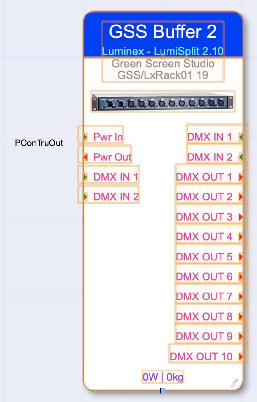
Are there any options or methods in the ConnectCad work flow to document power planning. I’ve used the spotlight side power planning but this isn’t always practical. Attached is how I document the power to show the flow through the schematic. Is there a way to trace the route that this goes through to the end device; showing which devices are connected to which phase and ultimately calculating the power draw on each phase? tk

-
I was trying to rename the topic to include con_ My other question along the same lines. I want to create some custom panel connectors "con_tru1". What is a good rule of thumb on where I should create this. Should I copy the "connectors" file to my user folder or is there a way to keep the original ConnectCad connectors file as it is and create a supplement? Thank you
-
argh ok, this makes sense, copy that
-
@Conrad P I am trying to add customised graphic style, I tried copying the Socket.vwx file to my user folder and adding a new style by duplicating and editing. I followed the _IN, _OUT and _IO name structure, but don't seem to be able to get the style to populate in the "Graphic Style" field in the object info palette. Am I barking up the wrong tree?
-
Create 2D schematic symbols from lighting symbols
tk_ replied to Daniel Dickman's topic in ConnectCAD
So another thing I am wondering. How is it best to represent a rack item for example an audio amplifier. e.g I want to have an audio amplifier device in the schematic, I also want that device to be represented in 2D rack and 3D rack views, but I also want to be able to connect a cable to it so that it is part of the electrical power planning. -
Create 2D schematic symbols from lighting symbols
tk_ replied to Daniel Dickman's topic in ConnectCAD
Arghhhhh, I see I see, thanking for taking the time to explain that. This is very useful. I’ll have a play around with want information I can pull together once they are linked. thank you again tk -
Create 2D schematic symbols from lighting symbols
tk_ replied to Daniel Dickman's topic in ConnectCAD
So for example I create a new layer in my schematic and drag the lighting fixtures into that layer. I then select my ConnectCad device which represents that lighting fixture and I select the "Equipment Item" tool. When I hover over the lighting fixture spotlight item it doesn't seem to do anything. My devices don't seem to have any blue points either. Please can you elaborate a little. Thank you