Ian5100
-
Posts
18 -
Joined
-
Last visited
-
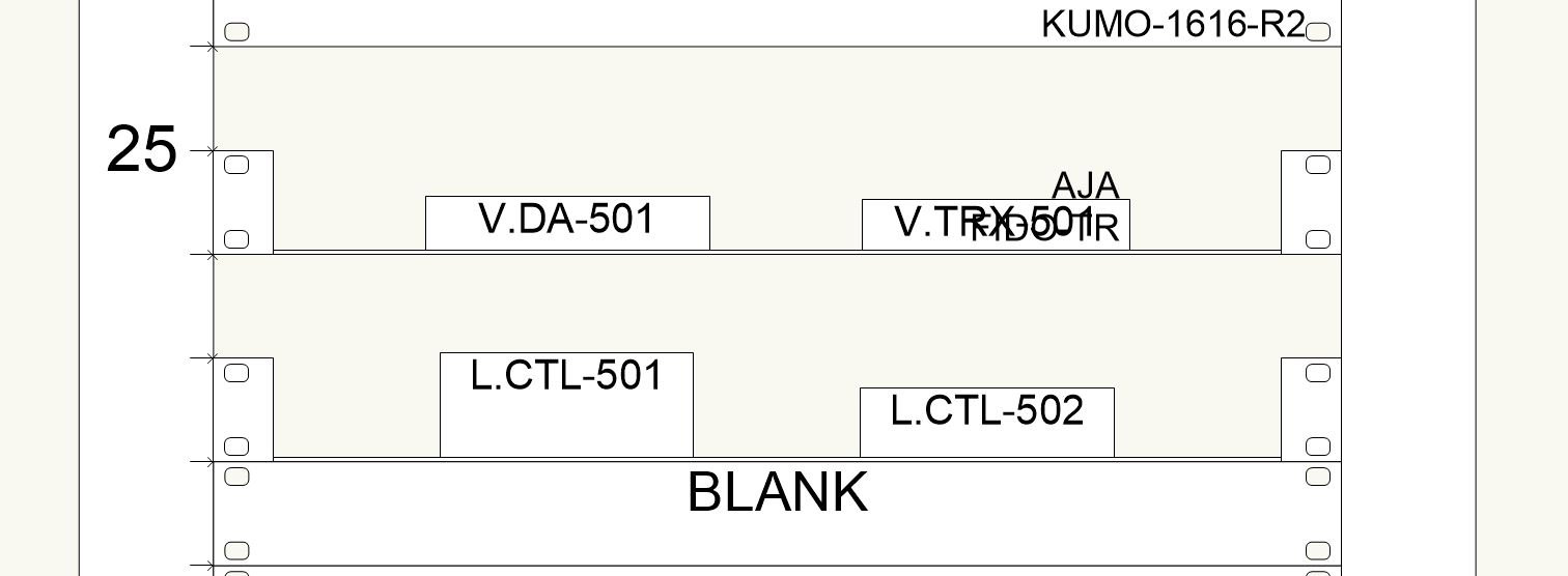
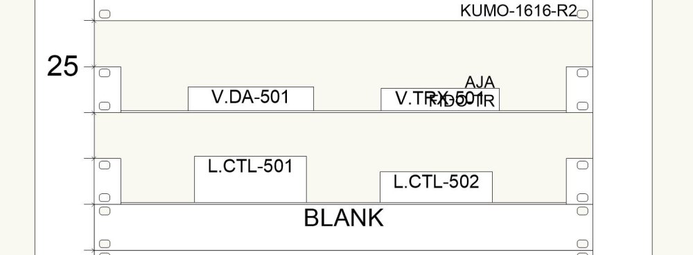
Thanks for the suggestion, I didn't know this feature existed. I'm playing around with it now, and it's not really giving me the behavior that I'm after. I didn't mention it in my original post, but I'm often going a little off-script to get things to look the way I need them to look in a rack elevation. I've included a screen cap of what I'm working on. I actually started this project in v2022 and am struggling to pick up where I left off in v2024. What I need to do is show a touch panel mounted to the front of a blank panel, and I was able to just drop the touch panel device over top the blank panel in v2022, but no matter how I try to do this in v2024, I can't quite get it. I'll probably just have to hover the touch panel in front of the rack and manually create a section view to see it, then manually enter the rack information on the device using custom properties. I would think either hide the side panels, or have the the option. Thank guys! These will be a big help.

-
First off, I think the new 3D rack editing is pretty nifty. It's something I wish that I was able to do before instead of getting a monolith that I'd have to redraw any time I made a change to the elevation. That said, there are a couple things I'd like to see: The ability to edit a rack while using the clip cube. I'm not sure if I'm doing something wrong, it would be nice to not rotate the entire world when I want a different view of the rack I'm working on. The option to work in just 2D. Most situations, at least for me, just don't call for modelling the entire rack in 3D, and as such, don't justify the headache of working in 3D. It would be nice to be able to just slap together a quick and dirty elevation like we were able to before. I've seen it elsewhere in the forums, but a tray that does not have slots. The slots are cool, but more often than not, I'm putting devices with different form factors on a single shelf, and I'd like to show them as they would appear in real life. The option to create a side view elevation. I know I can do this manually, but it seems odd to be forced to model the rack in 3D, but then not have the option to auto-magically create front, rear, and side views. Otherwise, I'm really enjoying the upgrades made in 2024, and I appreciate you guys continuing to improve ConnectCAD. Thanks!
-
I would like to be able to display a socket's connector type on the drawing without having a circuit connected to it. I've figured out how to achieve this by adding linked text to the socket text symbol and making it look like the default connector text. However that text appears bold when a circuit is connected and its connector text overlays on top of my connector text. Is there a way to turn off or make the text invisible when a circuit is connected? Is there another way of achieving this that I haven't thought of? (Here's a screenshot of what I'm doing.)
-
@Nikolay Zhelyazkov In that same vein, it would be nice to be able to number sockets with letters as well. I like to match what is printed on the device whenever possible, and I often find myself having to either enter every socket separately in the builder, or using the renumber tool after the fact like you suggested.
-
In the device builder in 2021, we were able to tab through and type in all of the fields in socket definition without having to touch the mouse. Now in 2022, we have to click two or more times on each field to edit them. It looks like the socket definition area has been completely redesigned, so it may not be possible, but I would love to be able to navigate that area as quickly as I could in 2021. As a side note, I am a fan of the more easily searchable signal and connector fields, as well as the ability to rearrange sockets. Those features have been on my wish list for a while.
-
@Conrad Preen Is this a new feature in 2022? I'm still not seeing it in 2021. Once I'm through this project, I'll be switching over to 2022, so it's no big deal if it is. I can just put the device on a non-plotted layer to get the rack/rackU information and manually draw it how I want it to be. Thanks for the help! I appreciate that you guys are always responsive and insightful.
-
@Conrad Preen Thanks for filing the bug, much appreciated. I remember seeing the option to hide all text, but when I went to use it per your suggestion, I couldn't find it. It was a checkbox under the "Display" heading, right?
-
For the most part, ConnectCAD does a pretty good job of sizing/enabling/disabling a device's make/model in the front elevation view. However, when I have a device that is less than 1U tall, this function often struggles. I've included a picture of such a situation. After reading through other similar threads, I understand that you guys try not to overload the elevation tools with features/customization that might be intimidating for newer users. That said, it would be nice to be able to simply hide make/model on devices. Is this something you would consider adding? Thanks!
-
@Nikolay Zhelyazkov I looked into it, and you're exactly right. While I didn't change it in the middle of this project, I did change our starter file from metric to imperial and changed the snap grid size, all without touching the loop symbol. So I just opened up the loop symbol, and sure enough, the sockets are spaced according to the old grid size. This is going to save me a lot of headache. Thanks for the insight!
-
@Nikolay Zhelyazkov Sure thing! I'm on version 2021, and here is that sample file. IO Loop Issue Sample File.vwx
-
I am running into an issue where the bottom portion of the IO Loop socket is not aligned with the grid. I've included a screen cap showing the problem socket. My best guess is that the grid size (1/16") that I have set is smaller than the minimum size of the IO Loop socket. Does anyone know what is causing this and/or a solution/workaround? Thanks!

-
@Conrad PreenThanks for the tip! I've had good success using a workgroup folder to share devices, signal types, and connector types with my teammates. The only trouble I've run into is that when I create a new device using the Device Builder, the new device is added to the DB document in my personal user folder, and not the workgroup folder. Is it possible to have devices added to the DB document in the workgroup folder instead of my user folder? Otherwise, are there any good workarounds that don't require us to manually add the devices we create to the workgroup DB file? Thanks!
-
@Nikolay Zhelyazkov That solved it! I had renumbered those sockets after connecting them, and it looks like the nudging up and down trick is working pretty well to update their connections. I'm afraid to use Reset All Plugins, because I went a little off script in some areas to get things to look the way I wanted. But I'll definitely keep that in mind for future projects where I don't engage in such Vectorworks debauchery. Thanks for the help!
-
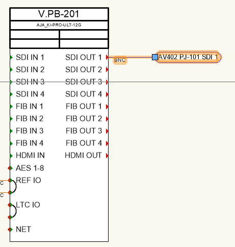
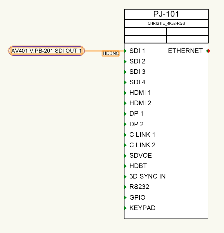
I've just notice that on some of my arrow connections, the port name is being cut off at the ":" The vast majority of arrows on this project are displaying correctly, but a handful are having this issue. Is colon a bad character for a port name, or is this a bug?

-
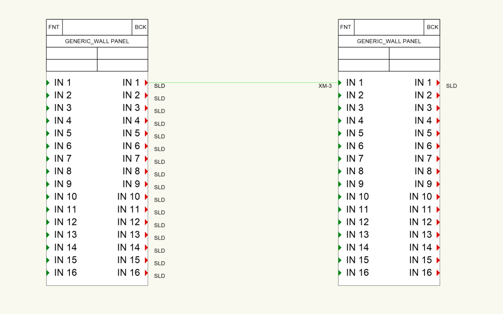
I've noticed that for an inter-layer arrow, the grip to move the flag around only shows up on the source side, and not the destination side. Is this a bug or am I missing something? (This grip shows up on both sides for an arrow that does not traverse layers.) Thanks!