BSeigel
-
Posts
118 -
Joined
-
Last visited
Content Type
Profiles
Forums
Events
Articles
Marionette
Store
Everything posted by BSeigel
-
Caustic photons will drastically increase rendering time. You would need to ensure that you have caustic photons enabled on each of your light objects as well or it won’t have much of an effect. Furthermore, caustics aren’t necessary for making high quality glass renderings. To get you more familiar with the various settings I’m going to include some links to our instructional content on the matter. https://www.youtube.com/playlist?list=PLiLCoe7DU1Hao1ig-Z_1KHHhIG8onnaUU https://www.youtube.com/playlist?list=PLiLCoe7DU1HY-bMr7_pFQIcacqM6f0ZMN https://www.youtube.com/playlist?list=PLiLCoe7DU1HZkZR_e9VABKT5WQW274sxj
-
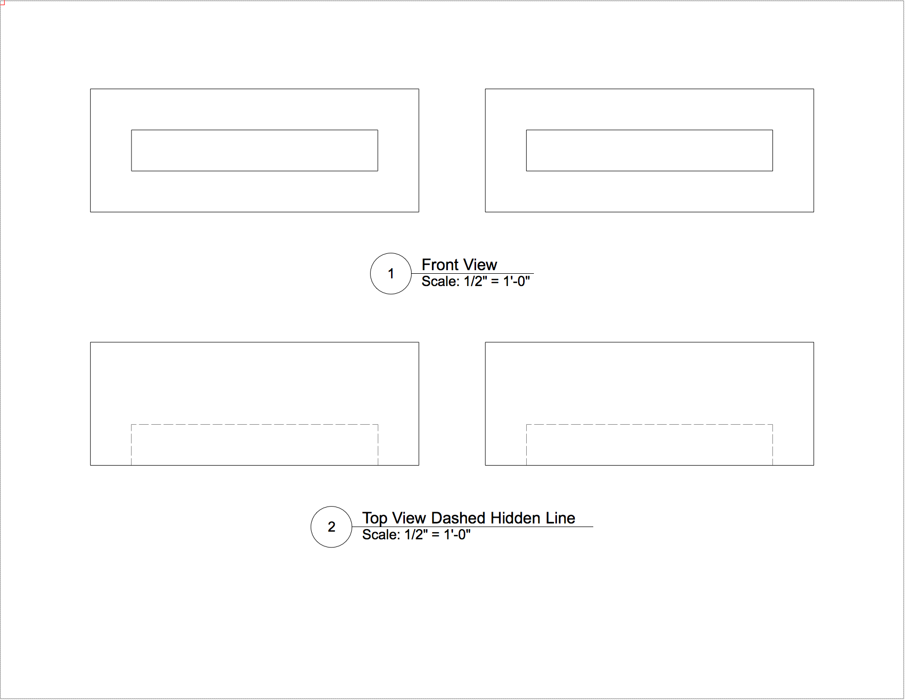
Which light object are you using? Also, if you change the Display Light Objects setting to "Only in wireframe" lighting objects will not display in OpenGL, Fast Renderworks, etc. If you change it to "Never" the light objects will disappear entirely from the drawing which may only be useful temporarily. (You could still edit lights through the visualization palette)
-

How to add a HDRI background outside a window?
BSeigel replied to anniemitch's question in Troubleshooting
Are you using a custom Renderworks Style? -
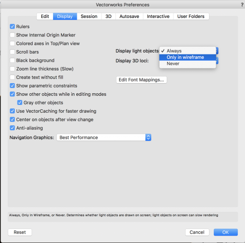
Here are few things you may want to check: 1. Make sure your graphics card driver is up to date (the latest version can be obtained from the manufacturers website) 2. If you have a dedicated graphics card, make sure Vectorworks is using it and not the one integrated with your processor 3. Try changing the Navigation graphics setting to Best Compatibility or Good Performance and Compatability
-
VW 2018 Snap to angle not working - not possible to move objects horizontally
BSeigel replied to Nick London's question in Troubleshooting
It is very likely the issue has to do with updating to Mojave. -
2019 Final Shaded Polygon No Longer Renders Simple Geometry
BSeigel replied to pharcus's question in Troubleshooting
Couldn't replicate the issue on my machine, are you able to share the file? Side note, if you use OpenGL and enable draw edges you can achieve a very similar result with faster rendering times. .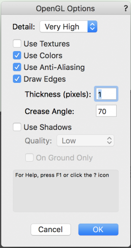
-
Files made in VW 2018 - Lighting Not Working in VW 2019
BSeigel replied to rjtiedeman's question in Troubleshooting
@rjtiedeman Without a photo it would be hard to say what the issue is. I would first check that your ambient lighting level has not changed between the versions (View>Set Lighting Options). If you were looking for a quick fix you could create a viewport from a camera and then adjust the exposure by using a Renderworks Camera Effect. -
All Good, I'm excited to see what you'll come up with! This may be a good place to start:
-
@EAlexander It would certainly be a challenge. My goal was to provide a user with a workflow to accomplish a task that they wished to complete in Vectorworks. Honestly, I'm sure there is a better way to do this with or without using Vectorworks and this is simply what I came up with this morning. To answer your question, it might be possible to create a marionette that does what you are requesting. Simplifying the geometry and tweaking rendering settings would be the first step. Then, you would have to create the marionette in such a way that it would insert various symbol instances based on a set of criteria and you could change those through edit fields. Not my cup of tea and it would certainly take some time to create the marionette, but I'd still be curious to see what a savvy user might come up with. PS: just refreshed page and noticed @Kevin Allens post
-
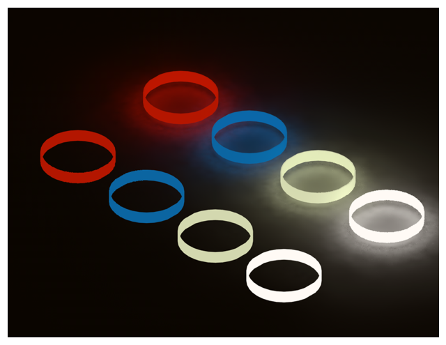
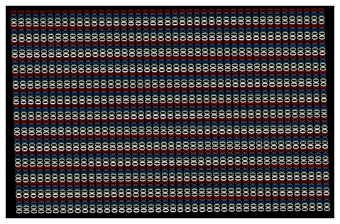
Rendering 2200 bracelets on medium settings without them emitting light took just over a minute on my machine.
-
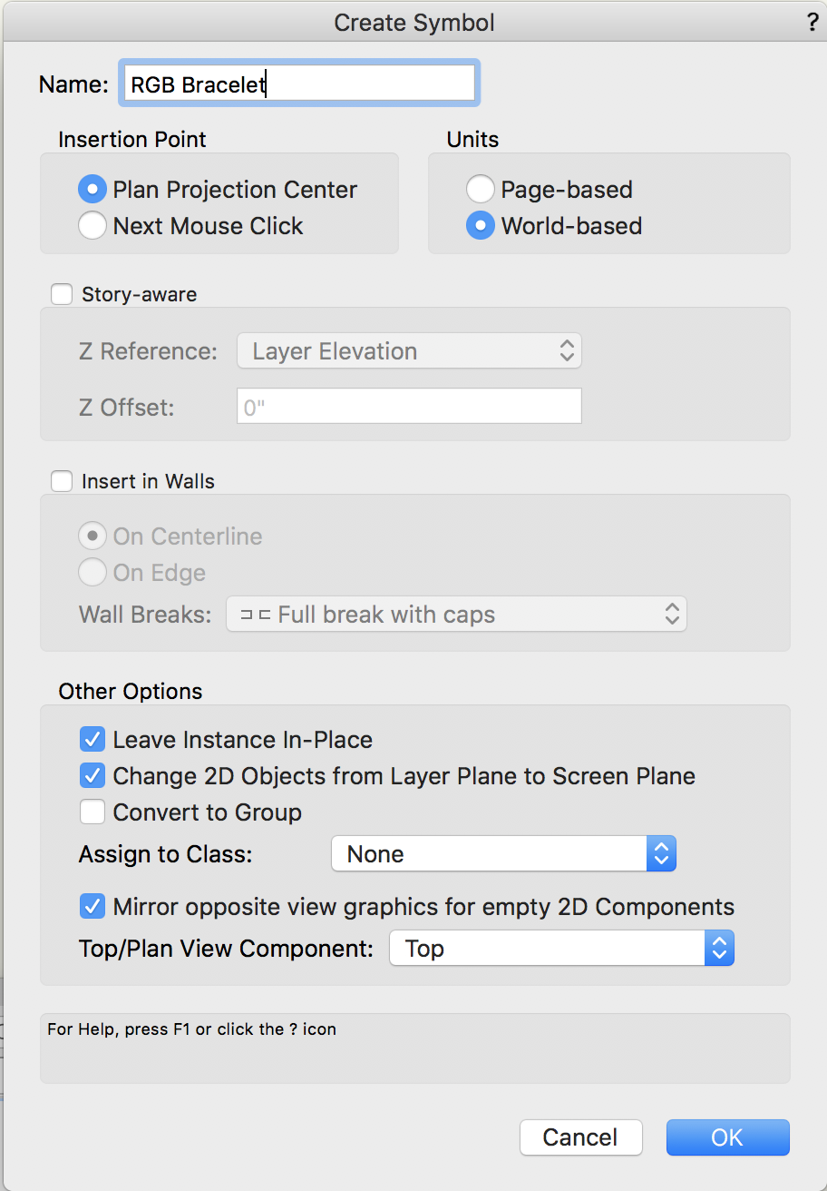
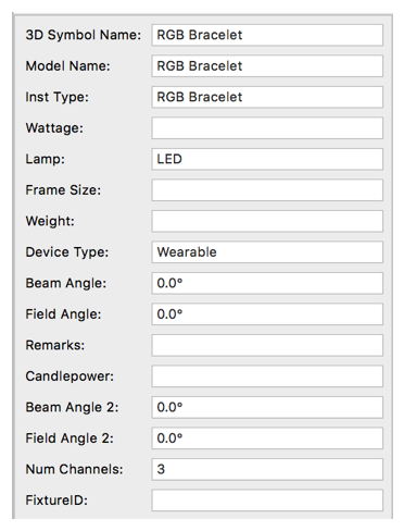
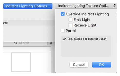
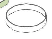
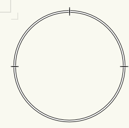
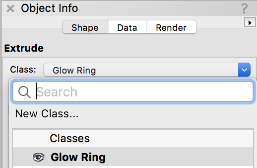
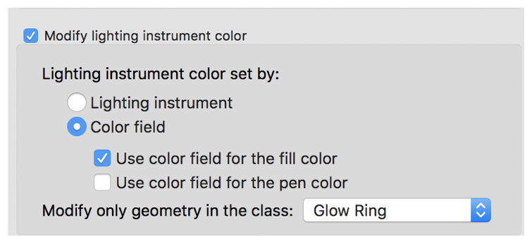
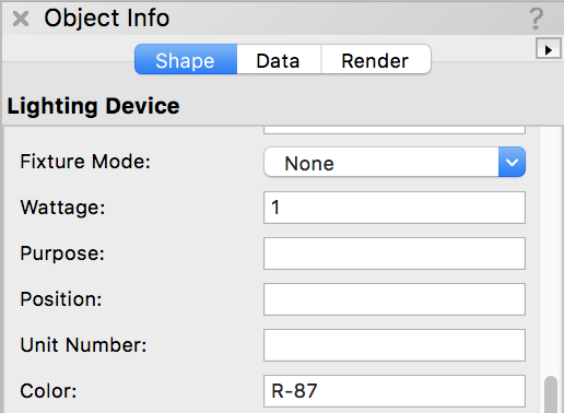
They're not wrong, this may be easier to do in photoshop...but I don't work for Adobe. So I'm going to show you how to do it in Vectorworks. I've attached my demo file in this post. RGB Bracelet.vwx 1. create a 2D ring that is roughly the size of a wrist, I went with 6in in diameter. 2. Take that ring and extrude it 1in . 3. Create a glow texture (If you check "Emit Light" under "Override Indirect Lighting" the bracelet will light up surrounding objects, but increase render time) My file has an example of both. 4. Apply the texture to your extruded ring. With the ring selected, create a symbol by going to Modify>Create Symbol. Use settings below. 5. Find the symbol in your resource manager, right click the resource and choose to edit the 3D component. When the edit window appears click outside of the object to deselect it. Go to the Data Tab in the Object info palette and select Attach Record. The resource manager will open and you will need to search for "Light Info Record", select the Light Info Record and that will attach it to the 3d symbol, next fill out the record. 6. Before leaving the edit window select the 3D object and create a new class. Then add the 3D object to the new class. I named mine "Glow Ring". Make sure to add the symbol in the design layer to this class as well. 7. This step is crucial. Go to File>Document Settings>Spotlight Preferences and go to the Lighting Device Tab. Enable Modify Lighting Instrument Color, Set by:Color Field, enable Use color field for the fill color. Lastly, set it to modify only geometry in the class that you created. This will change the color of the glow texture based on the information in the color field of the lighting device. 8. Now insert the symbol you created into your drawing by using the lighting instrument insertion tool. Then select it and change the color in the object info palette. Don't forget to right click the lighting device and select Turn on. 9. TADA! You know have glowing bracelet lighting devices that you can control! If you give them channel assignments it will be easier to select and mange them using the visualization palette. As I said earlier, I have some of these set to emit light and others do not. The ones that do not emit light render significantly faster. RGB Bracelet.vwx


-
Are you viewing the focus point in a Top/Plan View?
-
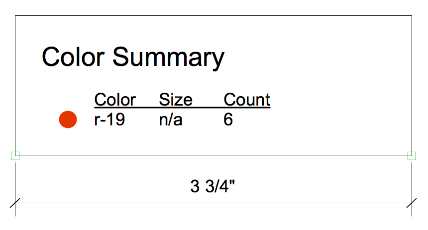
Just tried this in a blank file in 2019 SP0 and I did not experience the same issue. Please check the Column Offset, Left Margin, Item Spacing, Text Distance, Text Width, and Padding fields in the object info palette. As well as the Font size for your Header in the Object info Palette. If any of these fields are too large they will create a minimum width for the instrument summary that cannot be overridden by changing the Width Field. Give this a try and let me know if it helps.
-
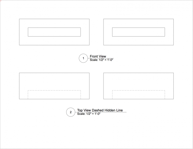
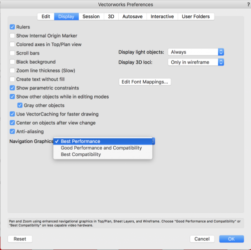
VW2019 - Is dashed hidden line rendering completely broken?
BSeigel replied to Kevin McAllister's question in Troubleshooting
The object on the right (the symbol) will display correctly if you uncheck "display 2D components" in the object info palette. If you delete the 2D Component from the symbol the object will display correctly in a dashed hidden line rendering as well. This does only occur after you change the line render settings dash style to a dashed line. The 2D component is just a solid rectangle that was covering up the hidden lines. If you use the generate 2D Graphics from 3D Components command you choose to create a 2D component using a dashed hidden line rendering mode. This will only display correctly in a viewport if you are in a top/plan view. Hope this helps.