Jesse Cogswell
-
Posts
649 -
Joined
-
Last visited
Content Type
Profiles
Forums
Events
Articles
Marionette
Store
Everything posted by Jesse Cogswell
-

How to record only the beginning of a value
Jesse Cogswell replied to Thomas Gillioz's topic in Marionette
I played with this for a couple of hours with little success. Marionette, and even Vectorscript, has no real easy way to get a substring with only character order, both have options using delimiters, though. In your example, if you are always going to have "O" after your story number like in your example, you could use that as a delimiter with a Split node to split the input string into a list, then use a Split List node with an index of 0 to split out the story number. The real answer to this would be to create a node that splits an input string into a list of characters which could then use the Split List and Slice nodes to divvy it up, but there doesn't seem like a way to do it with the default installed nodes. Or you could write a node that uses the magic of Python, which has robust built-in substring commands, to just return the first two characters of an input string. Unfortunately, I am not familiar enough with custom node creation to tell you how to do this, however.- 10 replies
-
- 1
-

-
- marionette
- ifc
- (and 3 more)
-
In the past, I've used the Ordered List node to sort stacking order, working from bottom to top (item0 is bottom layer, item8 is top). There used to be a correlation between the actual stacking order of the nodes to establish drawing order, but at least starting in VW2019, drawing order became kind of random. The Ordered List is the only way I've been able to consistently dictate order.
-
Adjusting Fixture Intensity/Output
Jesse Cogswell replied to Bradley King's topic in Vision and Previsualization
What I typically do when working with CF strips is to proportionally patch them at 65%. It makes the bottom of the dimming curve a bit rough (pop on when fading up from black, but they do that in real life, too), but it reads more accurately and is an easy change when you migrate the show file into reality. -
Zoom issue, 4K scaling, VW2013, dxdiag.txt
Jesse Cogswell replied to anarablehill's question in Troubleshooting
Piggy backing on what @LarryO has said, 4K might not be the best idea. You could try dialing down the resolution of your machine rather than changing the scaling, which would require less processing and will make the application GUI more legible. The easy way to do this is to right-click on the computer's desktop and select Display Settings. Then select your primary display (it should already be selected if it's the only display), and change the Display Resolution setting to something like 1920x1080. It might depend on the machine's aspect ratio, 1920x1080 is a 16:9 ratio, so if something looks off, then try some of the other options in that range. You will also want to set the Scale to 100% with that resolution. If you do want to keep your resolution at 4K, there is another possible fix to get Vectorworks to behave better on a 4K display. Vectorworks didn't get proper high DPI scaling until 2016 or 2017, as high resolution displays were incredibly rare in 2013, but Windows 10 has a method of controlling high DPI scaling that might fix your menus. To get to it, follow the steps below: Open up the Start Menu Locate Vectorworks 2013 and right click on its tile Under the "More" menu, select Open File Location In a File Explorer window, you should now see a shortcut to the .exe file for Vectorworks. Right-click on it and select Properties In the Compatibility tab, click on the button marked Change high DPI settings Click on the checkbox in the High DPI scaling override box, and try out the different options in the drop-down menu (System would be my first choice). I was using VW2015 when I got my first machine with a high res display and took forever to get Vectorworks to not have "an interface for ants." Back then, Windows didn't have an easy solution, you had to build an external manifest file for each application that needed to be scaled and futz around with the system registry to even get close. I still run Adobe Photoshop CS5, which also doesn't have high res scaling, so I have to use the High DPI scaling override with it. -
Setting how a drawing centers on the Internal Origin
Jesse Cogswell replied to AmandaM22's question in Troubleshooting
@AmandaM22 Unfortunately, the only way to get the internal origin back on track (in this case, the CL PL intersection), is to physically move everything. The way I typically do it is to make sure that all classes and layers are turned on (create a saved view saving the layer and class visibilities first to quickly get back to your visibility settings), make sure your class and layer view options are set to Show/Snap/Modify, then do a Select All and click and drag your desired origin back to the Internal Origin. Then use Tools - Origin - User Origin and click on the option "Set User Origin to Internal Origin." One of the major bummers is that you will likely have to redo any viewport crops after doing this. After needing to do this a couple of times, I've made it a point to never use a User Origin and to always have it match the Internal Origin, so any theaters that I draft I always make sure to put CL-PL on the Internal Origin when I start. Unfortunately, it seems a lot of draftspeople don't do this, and to be fair, VW makes the Internal Origin thing more than a little opaque. I can't remember if it's set on by default, but it's also why the very first thing I do on a fresh install of Vectorworks is to make sure the "Show Internal Origin Marker" preference is turned on in my display settings. -
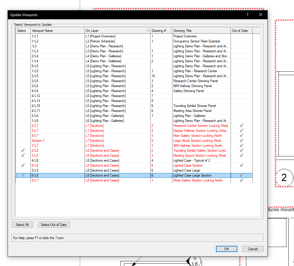
@Kevin McAllister Since VW doesn't seem to have any interest in adding this, I wrote you a workaround. Running this command will open a dialog box with a list browser containing all of the viewports in the drawing (on either Design Layer or Sheet Layer), listing the viewport's Name, Layer, Drawing #, and Drawing Title. If the viewport is "out of date", the text in the list browser will be red, and a check box will appear in the "Out of Date" column. All columns are sortable, with Layer being sorted by default. There are also two buttons, one to select all viewports (though I don't know why you would use it, but I'm not your boss), and one to select all out of date viewports with a single click. Screenshot of Dialog Box I'm sure that you are familiar with the plug-in installation process, but in case you need a refresher, follow the steps below: Download the attached .zip file. Open Vectorworks. Go to Tools - Plug-ins - Plug-in Manager Click on the Third-party Plug-ins tab Click on the Install button Select the .zip file Click OK Restart Vectorworks Go to Tools - Workspaces - Edit Current Workspace Click on the Menus tab In the left box, find and expand the JNC category Click and drag the Update Viewports command from the left box into the desired menu in the box on the right Click OK I did a couple of tests in both Vectorworks 2019 and 2021 and it seemed to work. Let me know if you encounter any odd behavior. May this save you some much needed time. Update Viewports.zip

- 10 replies
-
- 15
-
-

-
Opening a student saved file with a professional license 2021
Jesse Cogswell replied to Oona's question in Troubleshooting
@Oona I advise students and interns fairly often who are using the student version of the software and have never had a problem opening their drawing. You will usually get a dialog notification that the drawing is watermarked and using assets out of the drawing will watermark other drawings. The watermarked file will functionally be the same as a standard file except it will have a big "Vectorworks Educational Version" bug on the top and bottom of each printed plate, and any PDF exports will be locked down. It's a pain to work with and I get very annoyed when a collaborator sends me a watermarked drawing in a professional setting, but it's totally workable. The only time I've ever had VW refuse to open a drawing is if it was made in a newer version than you are trying to open it on, or if the drawing was created on an illegal copy of Vectorworks, which I've only ever encountered once and outside of refusing to open the drawing, it will actually launch a browser window explaining the situation. All that being said, this is the case for North America, I don't know if international versions are more locked down with their Educational licenses. Watermark warning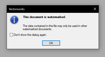
-
Converting from Vectorworks 2021 to 2020
Jesse Cogswell replied to Sade's question in Troubleshooting
Here you go. 3d model v2020.vwx -
Converting from Vectorworks 2021 to 2020
Jesse Cogswell replied to Sade's question in Troubleshooting
@Sade Here you go. TESTER_v2020.vwx- 5 replies
-
- 1
-
-
- help
- troubleshooting
- (and 2 more)
-
Drawing the floor of amphi (like a rise)
Jesse Cogswell replied to Safak Sari's topic in Entertainment
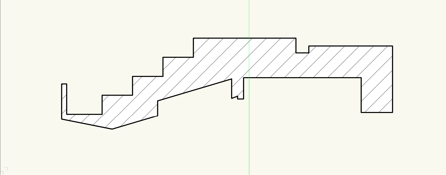
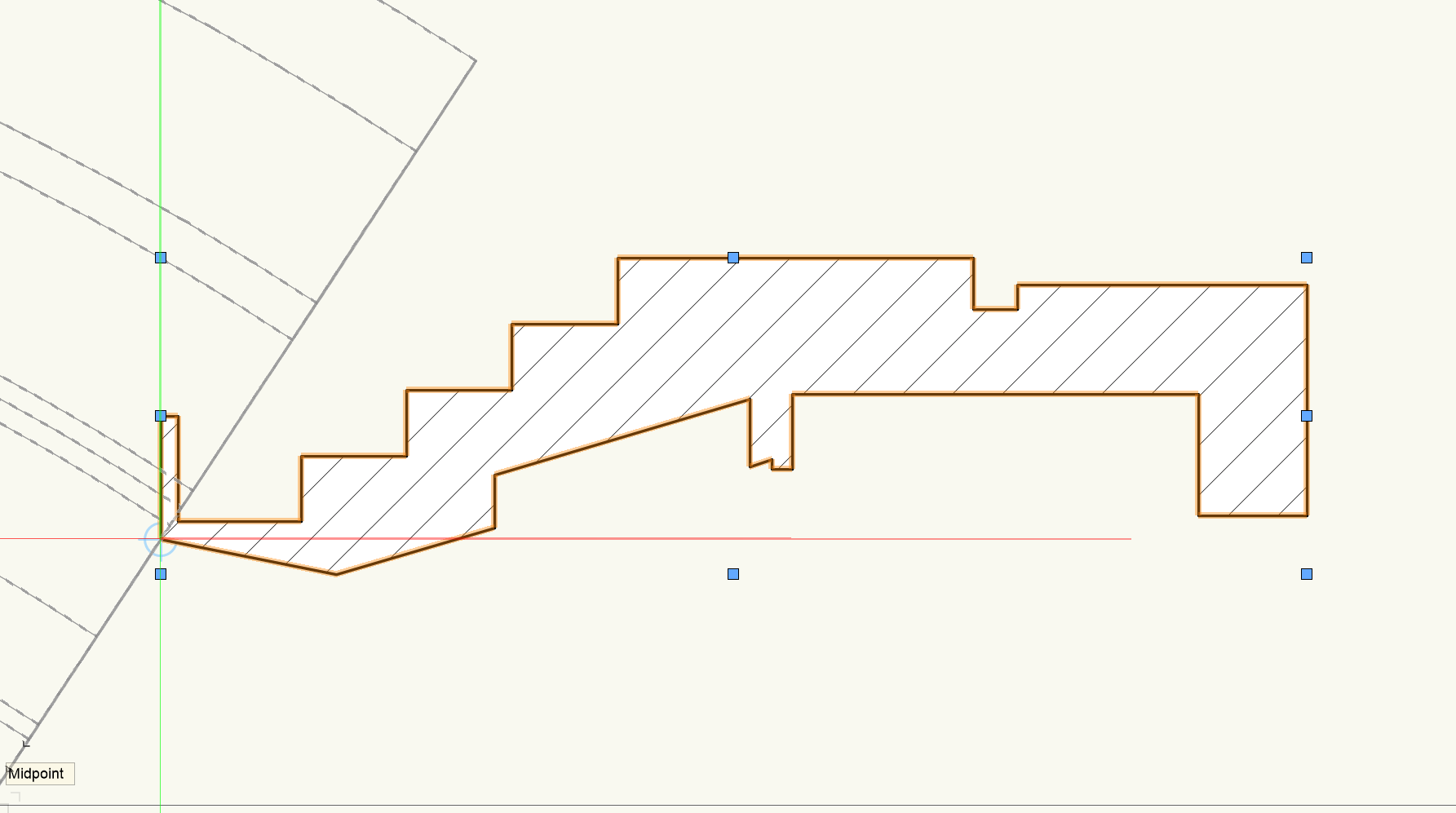
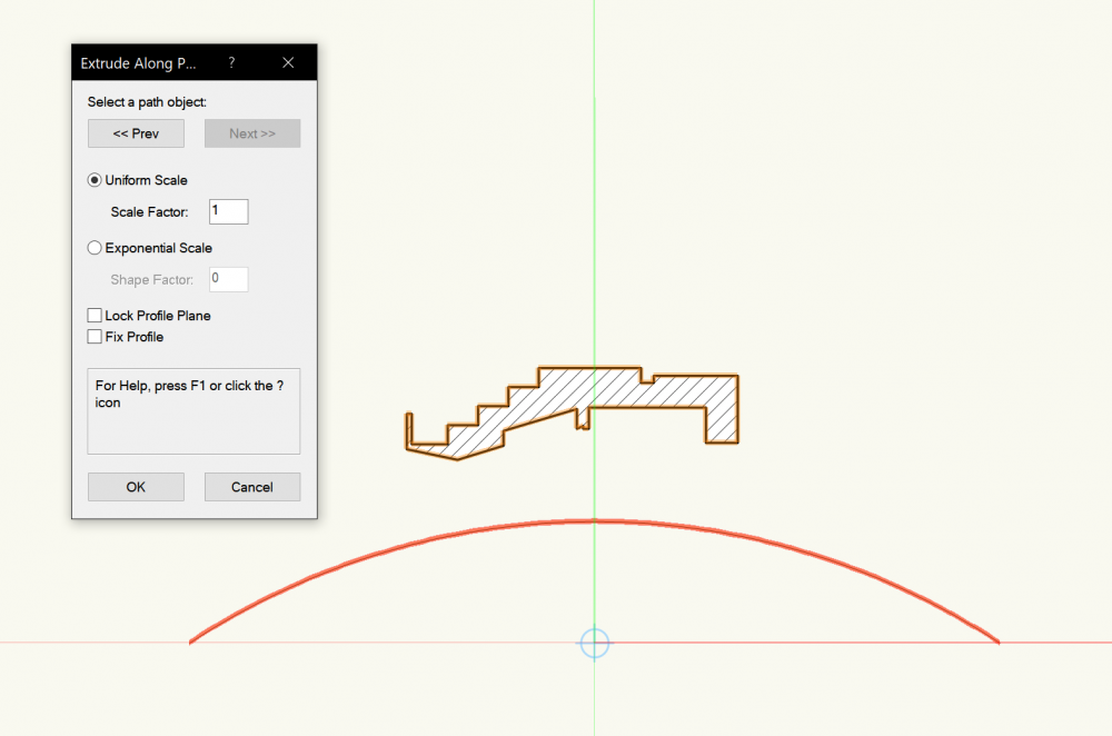
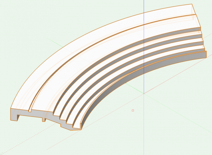
This is best done using an Extrude Along Path. If you have a section view of the venue, use that to make a closed polygon/polyline of the profile. Then, draw an arc representing the path. If you have a plan view of the space, you can easily draw the path using either the arc tool or the polyline tool. Once that's done, select the profile polygon and the path arc, then click on Model-Extrude Along Path. A dialog box should pop up allowing you to select which of the two objects is the path object (highlighted in red), click OK and the the Extrude Along Path will be built. IMPORTANT NOTE: Vectorworks will treat the path as the exact center of the extrude, so if you use the bottom step in your example to draw your path, you will need to move the profile after creation. Do this by double clicking the Extrude and select Edit Profile, then move the profile shape so that the "origin point" is where the path should be. Profile shape created from section view Selecting the path object (an arc in this case) Repositioning the profile Final Object All of this depends on what kind of drawings/resources you have to start with, but even if you have a rough idea of the dimensions of each "step" of the amphitheater and a rough idea of the curve, it should be pretty quick to build.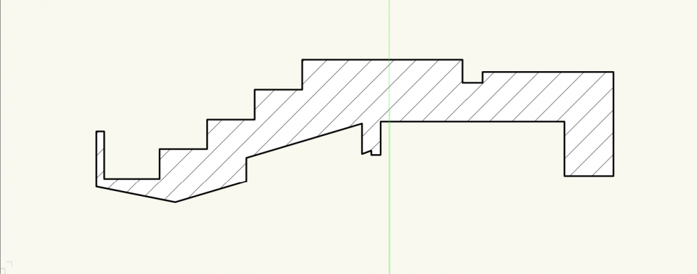

-
3D view of lighting fixture is incorrect...?
Jesse Cogswell replied to xotchil's topic in Entertainment
Make sure that the symbol has the "Parts" record attached. This determines which pieces of geometry are the Base (in this case, the clamp), the Yolk, and the Body. If the record is not attached, follow the instructions below. Edit the 3D component of the symbol Select the C-clamp Click on the Data tab in the Object Info Palette Click the Attach Record button Find the Parts record and double-click it. If this is not in your drawing, import any lighting device symbol form the VW library into your drawing. Below the Records box, there should be at least three check boxes, one for Base, one for Yolk, and one for Body. For the clamp, select Base. Follow steps 2-6 with the yolk, but select Yolk instead of Base. Follow steps 2-6 with the body of the fixture, selecting Body. Note that this needs to be a single object, so if the body is made up of multiple objects, you will need to group them before attaching the record. Also ensure that the body is pointing straight down. Ensure that there is a 3D locus point at the pivot point of the body. This is where VW will have the body pivot in the yolk, and will serve as the point of origin for the beam when Draw Beam is selected. Looking at your image, I'm pretty sure that this 3D locus is properly placed. This locus should not be placed in the body group. If the Parts are properly attached, then shoot us a copy of your file and we'll see what we can find. You can also try importing in new versions of the symbols from the VW library. Also, what version of VW are you using? VW2021 made some pretty substantial changes to Lighting Device objects, so there's a chance that the symbol you are using is out of date, but as long as the parts are still set, you should be seeing the fixture orient properly. -
@michaelk Oops, forgot to remove that criteria in the second script, since it's really not necessary. The ReDrawAll should cover doing the reset, at least it did in my (admittedly very quick) testing.
-
Here's the fix that should cover the redraw: PROCEDURE Test; PROCEDURE StompIt(h:HANDLE); VAR LW : INTEGER; BEGIN LW := GetLW(h); IF LW >10 THEN SetLW(h,10); ResetObject(h); END; BEGIN ForEachObject(StompIt,(INSYMBOL & ((LW<>2)))); ReDrawAll; END; RUN(Test); It's not all that clunky, really. I moved the LW variable in to the StompIt procedure since you don't need it to be global, and I added some indentation to make it a hair more legible. But the core script is about as elegant as it can be for what it does. The only change that I would consider making would be to add in a criteria for the ForEachObject procedure to only operate on the active layer (since DWG exports tend to be on a single layer immediately following import) to remove the possibility of accidentally overwriting intentionally set high line weights (I usually have a higher line weight on my title blocks, for example), or to just set all of the flagged objects to setting the line weight to be By Class, as I think that would be more useful in the long run. This comes with the added benefit of not needing an additional callback procedure for the ForEachObject procedure. These changes are made below: PROCEDURE Test; VAR activeLayer:STRING; BEGIN activeLayer:=GetLName(ActLayer); ForEachObject(SetLWByClass,(INSYMBOL & (L=activeLayer))); ReDrawAll; END; RUN(Test);
-
Viewport / sheet layers content missing
Jesse Cogswell replied to Aurore B's question in Troubleshooting
@Mia Casa I keep the three most recent versions of VW and Vision on my computer. 2019-2021 of both softwares use black for their logos. So, on my taskbar there are three identical logos followed by three more identical logos. Might be worth a feature request for 2022 to use a different color. -
Some of it may be determined by the mapping type. By default, Vectorworks will apply the mapping using Perimeter, which I've found to flip textures on a pretty consistent basis. Try changing the map type to Auto-Align Plane and see if that properly orients the textures. Depending on the 3D solid type, you might have to map the top/bottom and sides separately to get all of the textures properly mapped.
-
@virk I've never been able to get the CreateShell function to work. It's looking for a NURBS surface, but I have no idea on how to properly extract the specific surfaces from a sweep object to use for CreateShell. Theoretically, for an elbow could use an CreateExtrudeAlongPath function using a circle representing outer dimension and another using inner dimension with the same path object, then a SubtractSolid command to create your shell.
-
Took a look at the Concentric Reducer plug-in in VW2021, I forgot about a "feature" added to OffsetPolyN starting in VW2020 in which the offset now takes the poly's direction into account. I reversed the points in the Poly procedure and now everything works as intended. Concentric Reducer.vso
-
I'll take a look at the code in VW2021. I use 2019 primarily as I find it to be the most stable on my machine, and there are some rather annoying and persistent bugs in 2021. For as much as Vectorscript generally doesn't change, every once in a while they will change a command and cause scripts from earlier versions to break, and I seem to recall OffsetPolyN to be one of those commands. I also didn't try using it in a metric drawing, there is a chance that OffsetPolyN doesn't respect document units (as you get deeper into the weeds of Vectorscript, you'll come to realize that there's not always a rhyme or reason to which units functions and procedures use, and it's not usually detailed in the Function Reference. I'm glad that you were able to get this working. Scripting in VW is incredibly powerful and one of the major reasons that I have stuck with VW in spite of the quirks and bugs. To answer your questions: All of the information from the Edit Definition dialog box is stored in the vso file including parameter defaults, plug-in strings, and tool-tip information. The only thing not stored in the vso file would be an external resource file (like if you wanted to have a drop-down menu to select common wall thicknesses, all of that data could be stored in a tab or space delimited text file), but any changes you make on a script through the Plug-in Manager stays with the file. Vectorworks will be far happier with you if you store the plug-in object into a symbol if you're going to have that many. The Concentric Reducer that you have outlined is very lightweight in terms of processing and memory usage, but each instance would be individually computed even though they're identical. Symbols are about as lightweight as you can get in VW, with each instance only needing to compute X, Y, Z, and rotation data while the symbol definition is computed just once. I'm a huge proponent of symbols for this reason, even if you might only have one instance in the drawing. I work with a lot of designers who seem to favor using Groups instead, and it drives me up the wall.
-
Based on your example file, I think a sweep would be a better option than a multiple extrude. Based on past experience, sweeps generate better wireframe meshes than multiple extrudes, important for Hidden Line drawings. The only time I would use a multiple extrude for something like this would be for an eccentric reducer, where a sweep would not be possible. With that in mind, on to the code. For a simple solid 3D cone, the coding is very simple. Steps are outlined below. You will need to create a new plug-in by going to the Plug-in Manager (Tools - Plug-ins - Plug-in Manager) and clicking on the "New" button. This will open a dialog asking for the plug-in type. In this instance, I think a Linear Object is the best type, which will be used to set the length of the reducer. Name it and click OK. With any Plug-in Object types, you will need to define some parameters before starting in on the code. To do this, select your script and click on the "Edit Definition" button. In the General tab, assign a category for your plug-in. This is where you will find the plug-in to add it to your workspace. In the Parameters tab, you will assign additional parameters above the given ones of your plug-in type. Important things to note is the Name vs. Alternate Name. The parameter name in the Name column is going to be what the code itself references, while the Alternate Name is the one that Vectorworks is going to show in the Object Info Palette. Having these separate allows plug-ins to be localized for different languages without needing access to the source code of the plug-in. In this instance, I would create two Dimension parameters, named diameter1 and diameter2 with alternate names being Diameter 1 and Diameter 2. There's no defined rules for parameter naming, but I tend to set their Names based on how they will appear in the code, so I tend to do uncapitalized, camel case with no spaces and use the Alternate Name to make something a little more friendly. Any Dimension type parameters MUST have a default value, so set this based on what the most common reducer you tend to use (such as 3/4" x 1/2"). The other tabs don't really matter for this particular instance, but I'll detail them anyway. The Strings tab is used to define strings for localization purposes. If your object has text that appears outside of parameter names, such as dialog boxes or warnings and such, the strings should be defined here and called into the script using GetPluginString. I tend to build categories like "Dialog Strings", "Dialog Help Strings", "Messages", and "Miscellaneous Strings". Having these outside the actual code allows your plug-ins to be localized even when they are encrypted. The Properties tab allows you to select an icon, set projection requirements, and write out the tooltip help for your plug-in. The Options tab lets you set a couple of options in terms of how your plug-in will operate. Event-Based plug-ins allow you to customize the OIP with buttons or more aware parameters (such as a drop-down list populated with items from a particular drawing rather than being hard-coded into the plug-in). Events-based plug-ins are a whole different beast with a relatively much more complicated coding to get them to work correctly. The current documentation surrounding events isn't great, but there has been some discussion of filling it out with some helpful articles from a now-defunct website called VectorLab, so stay tuned if you are interested in events-based plug-ins. Other options include Reset on Move or Reset on Rotate, these are used if your plug-in does things regarding its location. If it creates a text box displaying its X and Y value as an example, you will want Reset on Move to be checked. Other than that, the Options tab has the standard Insert in Walls functions that symbols can have. Click OK to close out the dialog box. One more step before you can really get coding is to insert your new tool into the workspace. To do this, exit out of the Plug-in Manager and open up the Workspace Editor by going to Tools - Workspaces - Edit Current Workspace. You will find your new tool in the "Tools" tab in the left box under the category that you specified (or "Miscellaneous" if you did not specify a category). Click and drag your tool from the left box into the desired toolset in the right box. Click OK to close the editor and reset the workspace with your added tool. The code I used is listed below and also attached it to this post as "Concentric Reducer Simple.vso". I've added comments explaining how it is set up. Vectorscript is based on Pascal, so there's a couple of things that can be odd if you're used to more modern languages like Python or Java. PROCEDURE ConcentricReducer; {All methods in VS are either Functions or Procedures. Functions return a value, procedures perform a set of operations, though they can also return a value if you need to. To do so, specify a variable in the constructor with a VAR flag in front of it} {* Creates a 3D Solid object representing a Concentric Reducer pipe fitting Developed by: Jesse Cogswell VW Version: 2019 Date: 5/1/2021 Revisions: *} CONST {This is the constant declaration block. All constants in VS must be declared and initialized in one of these blocks. You do not need to specify types here, VS will determine the type based on the entered value. This block is not necessary if you have no constants, it's provided here by way of example} DUMMY = 0; VAR {This is the variable declaration block. All variables in VS must be declared in one of these blocks before it can be used. This particular one is the global variable block. Here, we'll declare the parameter variables} lineLength,diameter1,diameter2:REAL; {Between this point and the main driver block, you can specify any number of procedures and functions as necessary. VS compiles from top to bottom, so if you call a procedure, make sure the definition appears above the call} PROCEDURE CreateReducer(length,dia1,dia2:REAL); {Here is the procedure that actually creates the 3D solid. It takes in the length and two diameters and creates the object} {Creates 3D Solid based on given variables} VAR {Just as above, this procedure has its own variable declaration block. The variables declared can only be used within this procedure definition} Origin,A,B:POINT; sweepHd:HANDLE; BEGIN {I usually specify an Origin point but don't initialize it, this ensures that it will read as (0,0)} {Point types are a special Structure within VS which contains an X and a Y value. This information can be accessed by calling <point name>.x or <point name>.y} {Other special Structures include POINT3D, VECTOR, and RGBCOLOR types} {You can define your own Structures in the TYPE declaration block, though it's a bit more of an advanced usage. Information can be found in the Language Guide in the "Structures" chapter} A.x:=Origin.x+(dia1*0.5); A.y:=Origin.y; B.x:=Origin.x+(dia2*0.5); B.y:=Origin.y-length; BeginSweep(0,360,10,0); Poly(Origin.x,Origin.y,A.x,A.y,B.x,B.y,Origin.x,B.y,Origin.x,Origin.y); EndSweep; sweepHd:=LNewObj; HRotate(sweepHd,Origin.x,Origin.y,90); {Because of the nature of Sweep command, the outlining shape is created 90 degrees off from the created line and then rotated in place} END; FUNCTION CreateReducerH(length,dia1,dia2:REAL) : HANDLE; {Here is the same code as above but as a function to return a handle to the resulting object. This is useful if you wanted to use another procedure to change the object later, such as setting color} {Creates 3D Solid based on given variables and returns a handle to the resulting 3D Solid} VAR Origin,A,B:POINT; sweepHd:HANDLE; BEGIN A.x:=Origin.x+(dia1*0.5); A.y:=Origin.y; B.x:=Origin.x+(dia2*0.5); B.y:=Origin.y-length; BeginSweep(0,360,10,0); Poly(Origin.x,Origin.y,A.x,A.y,B.x,B.y,Origin.x,B.y,Origin.x,Origin.y); EndSweep; sweepHd:=LNewObj; HRotate(sweepHd,Origin.x,Origin.y,90); CreateReducerH:=sweepHd; {This is how you specify the returned value, it's <Function Name>:= <variable>} END; {MAIN DRIVER BLOCK} BEGIN {At the beginning of the Main Driver Block, I will always transfer the OIP parameters, accessed using the syntax "P<parameter name>" into global variables. This is a personal preference, and you're welcome to just use the P<parameter name> call everytime you need the variable} lineLength:=PLineLength; diameter1:=Pdiameter1; diameter2:=Pdiameter2; CreateReducer(lineLength,diameter1,diameter2); {Best practice is to think in a modular fashion, with most operations being outside of the main driver} {Below is an example of the using the function instead of the procedure to create the object. Note that the handle would need to be declared in the global variable declaration block before this code could be used} {reducerHd:=CreateReducerH(lineLength,diameter1,diameter2);} END; Run(ConcentricReducer); {Final run statement to execute the script} Also attached is a similar script, "Concentric Reducer.vso" that will incorporate wall thickness to draw a more realistic tube shape. I won't go into the code here, but you are welcome to open it and noodle with it. There is probably a much more simple mathematic method of determining points for wall thickness, but as someone who hasn't studied trigonometry since high school, I opted to use an OffsetPolyN and IntersectSurface solution instead. Let me know if you need any help installing or opening these plug-ins, as the process is a bit complicated. Concentric Reducer Simple.vso Concentric Reducer.vso
-
There used to be a pretty good primer for Vectorscript in the native help file for Vectorworks, but they removed it at some point. I've attached it below. It's old, but Vectorscript hasn't changed much in the last 10 years since it's based on Pascal, which first appeared in 1970. Vectorworks has incorporated Python, which is a much less esoteric and more powerful language, but you're still hamstrung by the Vectorscript function library when you want to interact with VW, so it only really helps for data management. Another terrific resource is the Vectorscript Function Reference, of which an offline version is installed alongside Vectorworks. No idea about where it ends up on a Mac, but on windows it can be found in C:\Program Files\Vectorworks 20XX\VWHelp\Script Reference\ScriptFunctionReference.hml. I usually have this open on a second monitor any time I'm working in Vectorscript. I will warn that it's not exactly complete, some functions have no information at all other than outlining the constructor, and some are fully fleshed out with examples (though sometimes the examples can be less than helpful). The Developer Wiki site that others have posted about is also a good resource, as it can sometimes fill in the holes in the local version, but I find the local version much easier to navigate. VectorScript_LanguageGuide.pdf
-
That can be tricky on Mac. ETC Eos (https://www.etcconnect.com/Products/Consoles/Eos-Family/) is what I use and there is a Mac version, but you will need a Nomad dongle or physical console to get the software to output to Vision, so unless you have one of those things, it probably won't help much. Chamsys MagicQ also has a Mac software (https://chamsyslighting.com/pages/magicq-downloads). I've never used it so I don't know if you can get ArtNet or sACN output to Vision without having physical hardware, but it's worth a shot. Otherwise, there's Obsidian Onyx (https://support.obsidiancontrol.com/Content/Support/Downloads.htm) which I know can output sACN with the free software, but only appears to have a PC version. I'm afraid that you might not find too many users of Vision on the forums. Of the major previsualization softwares, Vision tends to be the least used, with Capture, L8, Depence2, and WYSIWYG being much more popular. I personally went with Vision because of the ease of getting a file out of Vectorworks quickly, but with the recent MVR export standard, this is now much less of an issue for other software. I mean, the built in visualizer in GrandMA2 and 3 do a damn fine job of visualizing moving lights, and the Chamsys visualizer is no slouch either. The ETC Eos software also has a similar tool called Augment3d, but it's a programming tool first with the previsualization being pretty substandard.
-
I have some ideas of how to make this work. Would it be possible for you to post a file with different configurations or examples of what you want to see? I might be able to work on this over the weekend.
-
I've never had a viewport generate a locus point, it's most likely that the locus point is somewhere on one of your design layers or embedded in the annotations space of the viewport (but unless you're generating the viewport through a third-party script, that locus point would need to have been placed by someone...). The way I would go about tracking it down would be to edit the viewport crop and see if I can crop out the locus point. If I can, it would tell me that the point is on a design layer. If I can't, the locus point would most likely be on the annotation layer of the viewport. If it is on a design layer, select the viewport, click on the Layers button in the Object Info Palette, and make sure all layers are set to "Not Visible." The result should be an outlined red box with red lines connecting the corners to form an X. Then, one by one turn the layers back on. When the locus point becomes visible again, that will be the design layer containing it. Then, double-click the viewport and select Design Layer, and the offending design layer from the drop-down menu. You should then be able to delete the locus point. If this does not work, could you post the file, and one of us could try to track it down? As far as I know, there's nothing in the process of creating a viewport that should generate a locus point on its own.
-
Identical fixtures, positions, focuses--different beam angles
Jesse Cogswell replied to JB_Tech3's question in Troubleshooting
There is for sure something wonky happening in VW2020. I opened this first in 2021 SP3.1 and it looked exactly as you would expect, so I opened it in 2020 SP5 and I'm seeing exactly what you are seeing. There appears to be a but where the focus orientation cannot be -90. Moving the focus point or the fixture 0.01" in either direction on the Y axis seems to alleviate the issue. At this point, I don't think VW will fix this in 2020, as it appears to have been fixed already in 2021. As a workaround, I would make the focus point objects on the SL side of the center 0.01" higher on the Y axis. That way your beams draw correctly and your fixtures are still in the correct position. Annoying bug, though. -
@Ross McLee Hmmm. The script should center the viewport for you. When viewports are created, they are created in relation to the existing page center on the design layer. I'll look back at this script when I get some time, maybe I don't have it read in the existing page location. It certainly centered the viewports in my testing. Ah, just tried playing around with it. It gets screwed up if your User Origin is different than the Internal Origin. If you run Tools-Origin-User Origin and select Set User Origin to Internal Origin, this should correct this. This is a big pain point I have with Vectorworks, as the Internal Origin is poorly explained but is what the GetOrigin VS command references. A lot of draftspeople start a drawing without regard to the Internal Origin, then set a User Origin later. There is no direct coding in VS to get the User Origin, you instead have to use a GetPrefReal(6702) and GetPrefReal(6703) and convert the units. So, if I'm feeling lazy and writing scripts for free, I tend not to put that scripting in. After I started scripting, every single one of my drawings is very cognizant of where the Internal Origin lands, usually on CL-PL intersection. When I get a moment, I'll add in the scripting to compensate for the User Origin, but that will probably be in a couple of days.