Claes Lundstrom
-
Posts
228 -
Joined
-
Last visited
Content Type
Profiles
Forums
Events
Articles
Marionette
Store
Everything posted by Claes Lundstrom
-
SVG export would be very useful. I use it for exporting print and cut scale models using a Silver Bullet cutter. The files include both high res images and vector curves for cutting. My method for generating SVG files is to export as PDF, open it in Affinity Designer, and then export as SVG which is opened in the cutter driver. Affinity Designer is highly recommended as an Adobe Illustrator alternative. Very competitive pricing and very capable.
-
The point of importing a model is to save time. In this case, re-skinning or fixing it up takes longer than modeling it from scratch. A lot. A few extrude along paths and you have a model in say ten minutes for a skilled user. You get solids, it renders way better, and the model takes up less space. SketchUp does not add anything here (it seldom does if you ask me).

-
https://www.posersoftware.com/
-
Convert to NURBS - Where are Interpolation points?
Claes Lundstrom replied to Benson Shaw's topic in Solids Modeling
I agree. Using interpolated controls is way easier as they are on the object and not vaguely beside it. Even better would be to finally update the editing of NURBS objects, which really needs an update to stay in par with other packages.- 3 replies
-
- 3
-

-
- convert to nurbs
- interpolation vertex
- (and 1 more)
-
3d powerpack unfold surface tool
Claes Lundstrom replied to Michael Carter's topic in Solids Modeling
It's true that there are limits to what you can unfold, but the boundaries are quite vague. VW has clearly made progress on this tool from being only usable on very simple shapes to being more average compared to many other programs on the market, having unfolding features. I did some testing on some objects being close to the limits and found that it did a decent job, though failed sometimes, and sometimes generated more errors than I would find acceptable for my personal use. In reality though there are an almost infinite number of solutions on such models, so it is hard to say what is right or wrong. My personal conclusion is that I still trust the results more from my more advanced program, which can do more and allows me to shape panels to be optimized for unfolding, and it also tells me where it goes wrong and what to do about it. In it's context though , I think the current VW unfolding works ok, as I assume that most users will never deal with more complex shapes. -
True that most 3D programs work in a similar way. In theory. However, programs having dedicated boat design programs tend to provide way better shape control than standard CAD / 3D modeling programs. How efficiently it works is another matter. Some years ago, a friend of mine, a professional naval architect, decided to draw a canoe in MaxSurf and TouchCAD. Both have dedicated boat designing features, but the same shape took two hours in Maxsurf and seven minutes in TouchCAD....
-
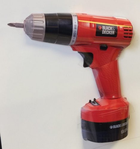
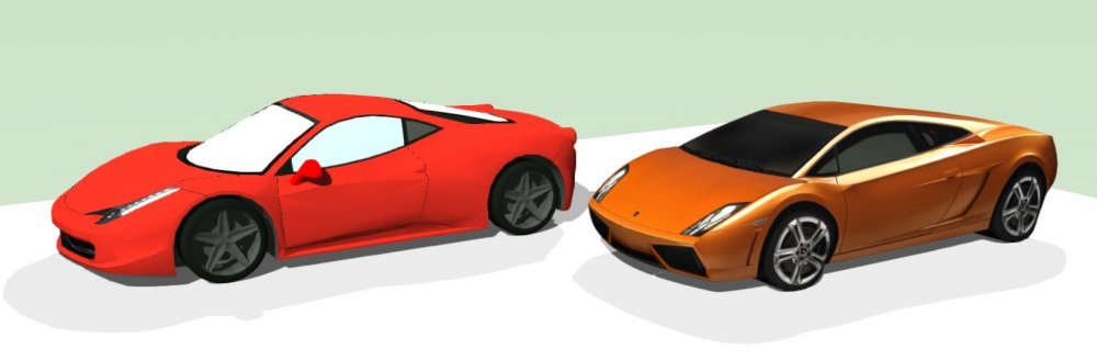
I don't know how much time I have spent rebuilding or adopting models to a practical level. You can usually import models i various formats, but the quality varies a lot. One reason may be that the suppliers use production models rather than models specially optimized for use as symbols. On for example a chair, the production model contains lots of details that you don't actually see in real life, or as a symbol, and can those parts can therefore be removed in the symbol version. The production models are simply way to detailed to be practical. You just want them to look good and be easily identifiable as a given product. In my experience, it is often possible to remove up to 90% of the model data and still have a model that looks pretty much identical to the original. It would be useful if the suppliers made an effort to make models for specific use as symbols. It would also be useful to make more use of textures for details, like it's done in the computer game industry. Most of the details is then processed by the video card instead of the main processor, which creates smaller models, still looks OK both with Renderworks and OpenGL, and renders quickly. In this example, the model to the right only consists of 14 NURBS surfaces plus proper UV mapping of textures. The models where renders in OpenGL.
-
Chris, of course it doesn't work from any view than the top view. What you effectively do is to extract a new version of the model as seen from the top view, rather than actually flattening the model. It's like using a camera to extract a view from the top view. You can't do that from the side unless you have some special software that manipulates the data. What you where used to from your previous program was to manipulate the model in a similar way that you manipulate a selection box in VW in the Object Info palette. Unfortunately, VW does not support a 3D selection box with the ability to manipulate the model in 3D, so the suggested method was simply a way to bypass this limitation. Admittedly it would be handy to do it directly as you first suggested, I do it all the time in my other CAD program, but you can't in VW.
-
Rhino's unfolding is for sure better, but I would not say that it's all that reliable or top notch.
-
3d powerpack unfold surface tool
Claes Lundstrom replied to Michael Carter's topic in Solids Modeling
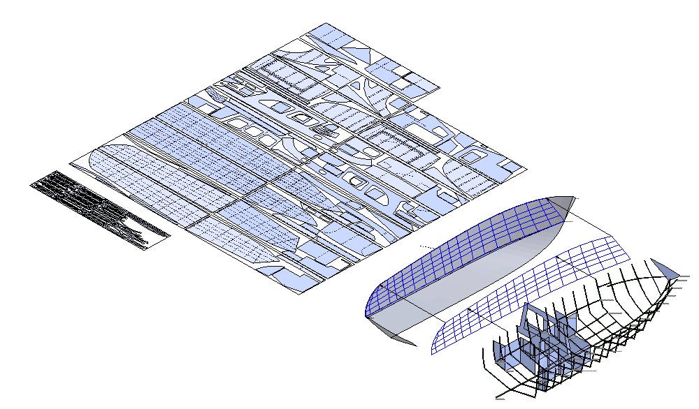
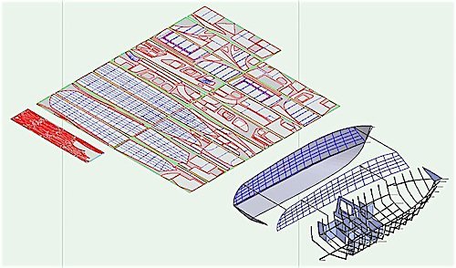
As a pro boat designer, I doubt that the unfolding in VW will be usable. It's just too limited. I only use VW for basic documentation when doing boat design. Here is an example having about 200 parts plus profiles made of high grade stainless steel, and nested for laser cutting. The unfolds also included on surface markings for precise positioning of connecting parts. The fit was 100% right.
-
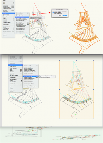
The Wireframe mode dialogue comes after having selected Convert to Polygons. The method will flatten the selection to zero height. If yo still want the object to be 3D, you can convert it back to 3D polygons, or set the Plane to Layer Plane in Object info. This allows you to rotate the model in 3D, though still having zero height in the Z- direction.
-
How about converting your 3D polygons to Polygons? Menu-> Modify -> Convert to Polygons -> Wireframe mode. If you still want 3D polygons, you can convert it back to 3D again. They will then have the same Z value.
-
I think you can get up to 10W now. They seem to have the disadvantage of generating an oval dot rather than circular, so it might be a good idea to wait for that technology to catch up. A CO2 is still a better technology from a cutting point of view, though also more complex with a huge and somewhat fragile tube, fairly sensitive mirrors, and requiring water cooling. In your case you also need to enclose the machine as the light is very powerful, but also to contain the smoke generated. Yes, I have had one in the past mostly for cutting Plexi glass.
-
A blue laser head should be easy to insert as it basically a small box where age milling uint is located. The Chinese ones are quite inexpensive.
-
It's most likely a question of using the right elements in the drawing. CAM, cutter controller, etc programs are often very limited in what they accept and can process. As a rule, it's therefore recommended to keep things as simple as possible. Avoid symbols, Polylines, Polylines defined as a filled surface (with holes in it), filled objects in general, possible groups, etc. A rounded rectangle is a Polyline and they should be avoided as they very often cause all sorts of problems. Lines, arcs and polygons almost always work. What you can do if you have a problem is to run the Decompose command before exporting, export, and then run Undo to get back to the civilization again. I have found that it almost always solves the problem.
-
Wish VW would support SVG as it gives yet another alternative to exporting to Adobe Illustrator and similar. You can use EPSF and DXF but the DXF import filter in Illustrator and many cutting programs are very unreliable.
-
possible to import 3D Objects made with Blender into VW?
Claes Lundstrom replied to Phileas's topic in General Discussion
The solution to the ZY problem is to have a flip dialogue whenever there is a 3D conversion, in, as well as out. VW does it..... sometimes. -
possible to import 3D Objects made with Blender into VW?
Claes Lundstrom replied to Phileas's topic in General Discussion
OBJ should work, though VW could do with some improvements, for example a dialog where you state the up direction (Z in VW, Y in many rendering programs). Support for plain colors would be good too (textures seem to work ok both in and out from VW). And a scale factor function, as many of the "blob squeezer" types of programs don't care much about physical scale. Many of them work with very small models, which requires quite a lot of model searching when exporting and importing between CAD and rendering programs. -
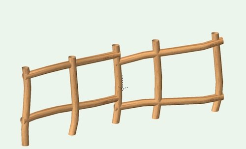
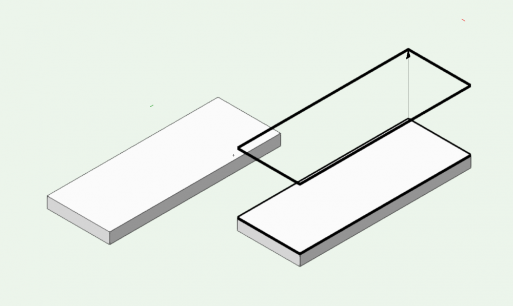
You can of course fake it in a viewport but that does it make it a 3D object. You can however fake it in 3D in OpenGL. OpenGL has one setting in the GL rendering setting for solid objects contours. You can however bypass that by using non filled objects such as 3D polygons, which do have their own setting using the settings in the Attributes palette. In this case I extracted the top face into a 3D polygon rectangle, made it unfilled, adjusted the line thickness and placed it ate the top. As you can see, it clearly differs in thickness (OK I may have overdone it a bit).
-
OpenGL can give you edge lines, but not individually controllable. You have to draw them by hand and give them a thickness. For edges, you can extract a face, and make it unfilled having a line thickness. The same applies to extracting edges as lines or curves and setting the line thickness.
-
Why odd ? Considering one myself. Had two 3D printers, one Co2 laser for cutting plastic parts, two knife cutting machines for cutting cardboard for scale models with printed textures. Considering one of these: https://shop.stepcraft-systems.com/D-Series , mainly because it can carry many tools using the same mechanics. Milling, laser head, knifes, pens, 3D printer heads, etc. Good if you have limited space. Also handy as all these methods have their plus and minus sides.
-
If it's 3D, you can trim it with an enclosing solid.
-
Been there, done that. All fabrics based examples. Same program.

-
I probably have the best program for complex unfolds such a boat hulls and all other parts of a boat for that matter. It does not just try and say if it works or not. It allows you to adjust the shape interactively as a part of the hull fairing, and it's probably the only program on the market that does so. I typically use this dynamic interaction to optimize the design so that it uses a minimal amount of material, and also interacts with the nesting of the panels. The example shows a 34 foot stainless steel boat having just under 200 parts plus various profiles, which we ran directly into laser cutting from the CAD files provided. The laser also added on skin marketings so that for example frames and bulkheads could be fitted without really measuring. We just placed the parts on the reference lines, which dramatically decreased the production time. The model was 100% generated in one program except for the renderings, and some documentation drawings done in VW.
-
VW is probably not the first choice for boat design. It's NURBS features are simply too limited. A few steps could bring VW to say average (like say Rhino), for example the ability to nudge control points (like with mesh points), the ability to edit any number of control points in any number of objects at the same time, etc. Rhino is probably the most commonly used program in boat design, though in my opinion it's a misconception to say that Rhino alone is a professional grade boat design software. It's not. It still lacks fundamental stuff like hydrostatics, dynamic cross sectioning, etc. You need to add a set of plug-ins called Orca, though I have to say after having evaluated it, it very much feels like an after construction. It's rather clunky to work with compared to dedicated boat design programs. It's therefore not a top contender in my opinion as a professional designer.