


Gadzooks
-
Posts
509 -
Joined
-
Last visited
Content Type
Profiles
Forums
Events
Articles
Marionette
Store
Everything posted by Gadzooks
-
I see where your coming from. The 2D drafting of a project is arguably the money. It needs to be completed quickly and efficiently in terms of the designer so all details are accurate and can be interpreted on site without questions raised. From that standpoint, the 3D and rendering could (should?) be put to one side until basic drafting needs have been met. But things move on. My alternative would be that that we use the join tool, make the irritating changes required to get it spot on, then use the eyedropper wall connection tool (you know, the one that's in VW 2018) to choose this (weighted skins) variation producing subsequent wall joins. I suppose a bit like Archicad, but this (crucially) would allow VW to maintain it 'leads rather than follows'. Lets see what 2018 brings...
-
Careful what you wish for guys. Layer after layer of complexity will be like the change from simple stair to the current stair tool (can anyone use it to create anything more than a simple stair ?). It appears to me the join component tool works ok in this instance. VW is not aware you want to join the Metsec - you might have wanted to introduce a 'disconnected joint" (for sound/thermal/other). The fact that you are able to use it to make a tweek to the initial wall join to provide what you wanted seems to give the best resolution. (I assume this is what@Jim Smithis alluding to?) Or are Jim and myself not getting it?
-
Good one. That rendering is almost life-like. To put rain on the window glass must have been a pain. I like the cluttered office look with boxes and paperwork. Looks just like mine. (BTW - I think I spot a cold bridge on the parapet detail.)
-
Thanks. Upped
-
Woah...now your talking. That would actually be a very useful bit of kit. If it had x and y capabilities it could also be used to set-out brickwork co-ordination on plans. Yes please @Jim Smith - If you could post the link it would be good to raise the votes on that one.
-
Mike - Yes, I've sometimes done similar things for my own versions of these 'simple' tools so my drawings have a consistent or particular style for different presentation purpose. Take the North Piont This is good, but there's no automatic element to the z readout - which I have to say is the one and only nice thing about the Elevation Benchmark Tool, especially if you are placing a few on the drawing and then make minor tweeks to it later to keep up with elevation height changes (Wouldn't a parametric connection to an element be good?). And this whole thread touches on any designer's wish list - I like the tool, but I'd like my own graphic/display/style attached to it. After all, Vectorworks allows so much of the interface to be modified to make it 'your own' (workspaces etc.) that it seems a shame these simple tools (I assume legacy) don't have a bit more flair, or access 'under the hood' to be creative. To this end, it would be really good if you could simply 'enter' the created object and change the boring iso/uk graphic similar to changing the 2d elements of a symbol. I might like a smiley face rather than an arrow! Or.... I'm thinking someone with marionette skills (and that certainly isn't me atm) could produce a nifty little insertion point that 'knows' where it is in the z plane (although having said that, why not make one that could be defined in xy or z) Users could create their own symbol for their preferred graphic and embed the 2d or 3d locus (so as to be invisible) at the correct read-point. The text style etc. can still be changed via the text tool, but the display would be accurately showing elevation. Someones going to tell me it exists (aren't they @Marissa Farrell!!!!)
-
 @justinekwoodIf you want to nudge with just the arrows, there's a little more to it. Nudge has user defined options you can access from Tools>Options>Vectorworks Preferences... Just switch the arrow key options to suit your preference. For example just arrow for Nudge objects can be chosen (as above). I would guess you were previously using a copy of 2016 that another user had set to their preferred default and (having got used to that) you expected the (as it turns out - default) 2017 to respond in the same way. Vectorworks is great in that you can 'make it your own', but using in a multi-seat environment (which I'm guessing you may well be in) can sometimes come-back-at-yer when others have set options you are unaware of. ..................................On the other hand, now you know what options are available, you might like a bit of shift-arrow. All the best.
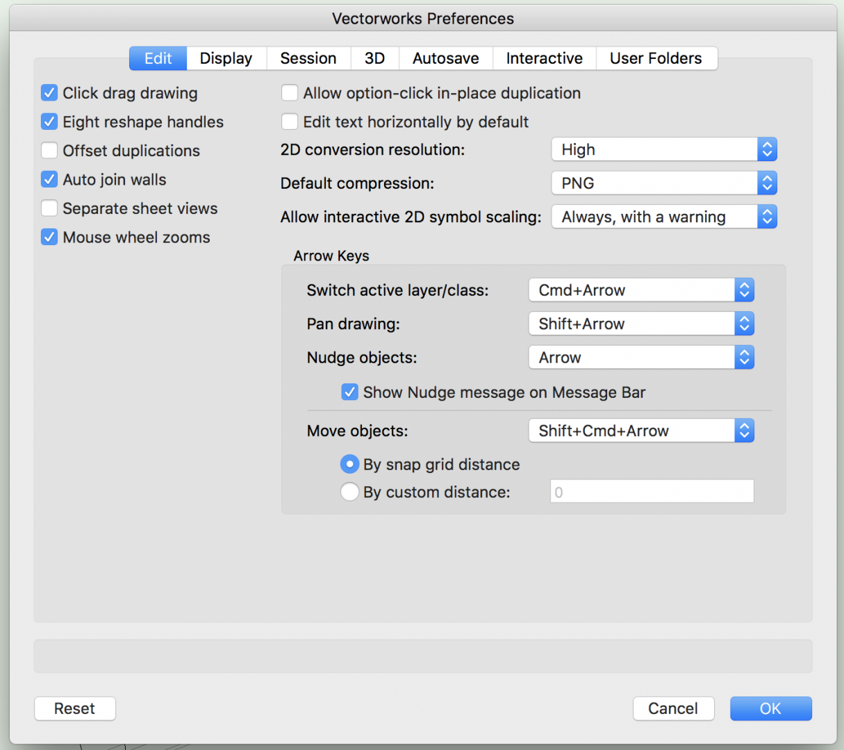
-
No worries. I did wonder whether there was more to your question.
-
Hi Halfcouple, If I understand your query correctly you wish to create a symbol between the 3d loci. I think this is best with Extrude Along Path. Someone else will perhaps jump in with a better way. Place the two loci in space using the xyz's for the two distinct positions you require. Now draw a NURBS (straight) line between the two points. Now draw a circle of required diameter - this will be your pipe. If you wish the final graphic to be more 'pipe-like' you might want to draw another circle on top and smaller to represent the correct internal dia and now Modify>Clip Surface. You now have either a full circle or, if you've chosen to, a 'sectional' pipe. Now highlight both the circle (however you've decided to draw it) and the line and choose Model>Extrude Along Path. The dialogue box wants you to confirm which of the two will be considered the 'path' - adjust if necessary so the NURBS line is the one highlighted in red. OK to that. You now have a 'pipe' drawn accurately between the two loci and you could now turn this into a 3D symbol for later use. If you want to save as a symbol it is a good idea to include the loci as part of the geometry. Hope this helps
-
Just wanted to give @PatStanfordand @Marissa Farrella big-up for the above. Getting your head around drawing with a CAD package can be daunting, but to be able to turn out tricks like that is (certainly for me) magic. Also shows people like me are only scratching the surface of VectorWorks' capabilities. Man, there's a massive engine under the bonnet (hood) and I'm only using it to pop down the shops... Such a lot to learn....thanks guys.
-
Dimensioning for Constructing Structures
Gadzooks replied to CraftyCat's topic in General Discussion
Surely your office/company has examples? Follow the company style and/or what is required by the build contractor - they may have particular requirements. (But you should already be aware if this is the case) If you've drawn it accurately, then the resulting dimensions will be accurate. Errr....unless you don't dimension accurately, so make sure you understand how the dimensioning tools work. This isn't something that can be taught via a forum. Happy to try and help if you have a particular issue with dimensioning. -
Yes, I can see the problem. Think this is the time to just suck it up and work with it rather than against it. So, Is there a reason to utilise a symbol (obviously you would if it worked!) because, for this drawing, there appears to be no reason you would want to go back and make any 'global' changes to all instances. There's the file size, but you could probably cope? Or, Maybe if the leccy and gaz (sic) boxes need to be annotated on your plans and you want to stick with the power a symbol offers, keep with just the coloured 'key' showing the box only, and place a legend somewhere on plan. I realise this is no good if you have copious notes on other symbols, but I'm not sure what they have in the way of information. Finally for symbol placement remember you can click and hold the symbol as its placed and then rotate to to position you want it to be. For this to work to your advantage you can utilise the 'on next mouse click' for symbol origin when you create it. Which you appear to have done on the example you've posted, as its on a corner of the plan layout.
-
Ive had a look at this. Although I don't count myself qualified - I'm just prepared to slog away at it as I know someone else on this great forum would do that for me. But this now has me beat. You'll have seen my thoughts on this to @Andrew Davies. In the end I wasn't sure wether the mix of 3d and lettering is just VW trying to make the best of where it thinks you want to view the 'space' you've created. What I am sure of is that ditching your symbol and converting it to a group seems to be rock solid and will reliably flip the text for you. As long as Adjust Flipped Text is set in the Document settings. I assume this is what you've found? What is clear is the hint panel that tells you that this option if chosen will flip text so its always legible in groups and symbols IS A LIE.
-
Kevin - I assume all these similar problems are 'fixed' by opening in 2016? If so, good job we were all offered a rebate on 2017 ;) @Andrew DaviesI'm just concluding that this thread displays similar characteristics to your problem with text. @Kevin McAllisterDid you see Andrew's question about text in symbol? Similar once again - Do you think its connected?
-
Happy to help, although I was concerned I might not have quite understood the complexity. If you say it changes when zoomed I'd be interested to see the video or maybe you can post the file?
-
Laughable if it weren't so serious and costs valuable time to practices who buy into VW with such blind faith (good band, but I digress). Seems big changes always trumpeted, but errors swept under the mat.
-
(I'm still in the cup'd) @Kevin McAllister- yes, similarities but annoyingly different. Plus, I don't see Modify>Compose helps - Did you try this, as it doesn't work for me. Unfortunately Hammy has groups rather than symbols so its really a problem on the old drawings that have numerous instances that would need every one changed. @hamrocksThe following proposal doesn't fix the reason for the symbols drawing incorrectly. As we all seem to be now concluding, I think this could be a bug as the end point handle has been allowed to stray and VW doesn't know what on earth to do with it?. But it may help you to take a different strategy with the numerous drawings that have this problem to save some tedious work - assuming you've not already come up with this yourself. Using classes (thank goodness you used classes), will allow you to find all the culprit symbols on the layer. Once the little critters have been identified and highlighted go to Modify>Convert>Convert to Polygons. This will leave you with them all grouped, but you can always Modify Group to (say) change the position of one or two. I assume that this will be a help on the older legacy files you have and will allow you to print etc. As for the new work, you will probably create a 'clean' symbol and start afresh. Hope this helps and - can I come out of the cup'd?
-
Probably shouldn't make your day worse, (why are you then??) but if it had been a symbol you'd fixed it just the once for all your drawings. (I'm going to go and lock myself in a cup'd now until I'm allowed out)
-
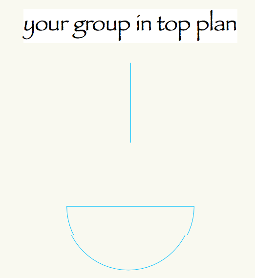
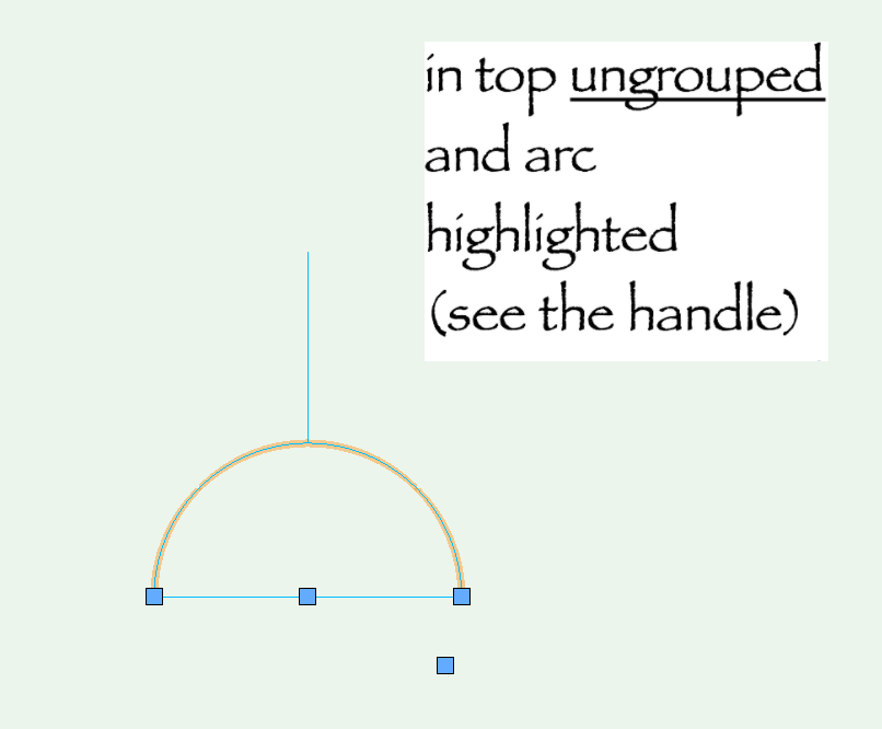
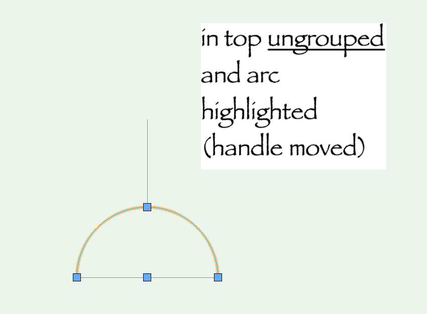
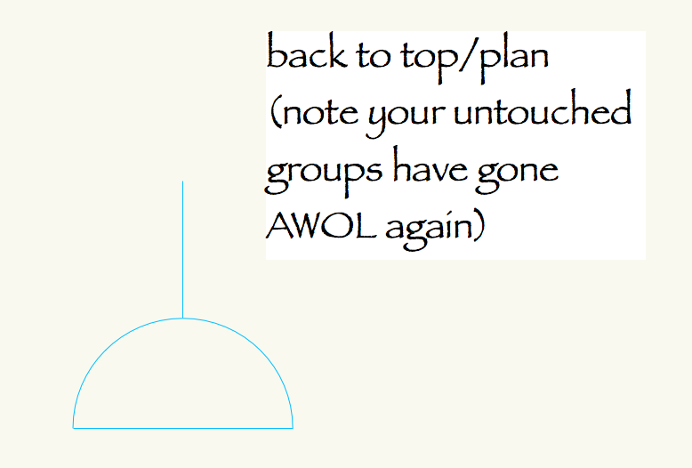
Hi - I'm still interested to crack this one. Kevin is definitely the main man, so don't want to steal the show, but looking at your file it opens in Top/Plan View. Have you seen what happens as soon as you change to Top View. Is this something that helps for the moment? (No? - I can hear you tearing your hair out from here) OK - It seems to be a problem with the arc as it has a 'floating' control. I just tried messing with this by duplicating one of your groups and doing this......(sorry I'm no good with video etc, but I think this proves a solution) The original groups on the same page (not unsurprisingly) returned to being AWOL Kevin will probably be able to identify why the arc handle is outside the arc - I would think it may well have been drawn incorrectly or have been corrupted?? BTW - I think you should then change your group to a symbol (most likely with the '2' as part of it) as you're using it to better advantage (file size) then. Over to you Kev...
-
Hamrocks - (on my earlier post) you will have seen that, with the layer elevation set to anything other than 0, it seemed to trigger the problem. Can you check this with your file. If you are using a '+' level it would be good to test back at zero and see if the problem persists. Not a fix, but at least it may confirm its connection to the bug.
-
Hi - The way I see it is that Vectorworks is working correctly with the information you've provided to it using 3D symbols. The image you've posted is in 3D 'space', albeit arranged to show a fairly simple 2d layout of numbered tiles. In this respect vectorworks can never know which way you want to view the tile layout. Let's say you wanted to look at the tiles in the vicinity of 'view c' from the underside. The tiles would now be seen to be at the top (north) of the layout and would be correctly displaying the number you've assigned. The change of 3D viewpoint is critical I believe. If you always want to use (that's to say view) as a 2d plan layout with views (ABCD) annotated as shown, I suggest you flip the 3D symbols to the correct orientation of the numbers so they'll display upright. More likely this is a 2d layout and should stay as such. I hope I've understood your problem correctly. Happy for you to give me a kick if I've massively missed the point.
-
I'm on Mac as well. Although I don't expect it to relate to Mac only - happy to play around with a file if you post it.
-
Hamrocks - this looks like a version of the issue I highlighted recently and has been logged as a bug. https://forum.vectorworks.net/index.php?/topic/50647-group-manipulationreshape-not-working/ If you could post a file with an example of this it may be easier to confirm. @Marissa FarrellWill most likely be able to comment in more detail.
-
A light hearted look at VW on a Friday.....so don't gang up on me! Ok - I've obviously got too much time on my hands, but using the North Arrow Tool why do the Configs that actually use an N - 1,6,7 and 10 not register dead centre? Unfortunately (must be I'm a little OCD) I see this straight away. Decompose them and run a vertical centreline to prove. I'm no graphic artist, but typographically an N doesn't warrant standing off centre does it? I don't call it being picky, I call it knowing what I don't want.
-
Flip & Rotate around insertion point / center point
Gadzooks replied to bcd's question in Wishlist - Feature and Content Requests
The rotate and flip commands are (as the menu hints state) for 'rotating' and 'mirroring' the highlighted object - so in that respect it does exactly what it says on the tin (that statement may be more obvious to Brits, so sorry if its not) Assuming I've interpreted your question correctly and you want alternatives to the basic operation, introduce a locus next to or within your object's bounding box and (with both highlighted) the operation Command/Control L (and/or the use of the additional shift with R,H and V) will rotate/flip the 'whole'. Just needs a bit of experimentation on where you would like the locus to be placed to give the desired result. This will work with any number of individual items + the (very useful) locus provided you highlight all of them at the same time. Bear in mind if grouped they will behave as 'one' and will use the (default) centreline which I believe is what you are trying to find alternatives for. If you need to have them grouped for convenience just 'edit group', carry out the flip operation to suit your requirements and 'exit group'. Hope this helps

