Gadzooks
-
Posts
509 -
Joined
-
Last visited
Content Type
Profiles
Forums
Events
Articles
Marionette
Store
Everything posted by Gadzooks
-
Spot on - I generally reduce to 600 which seems reasonable on the forum page. And dragging into into place would be a nice touch.
-

SHEET LAYER - FOREGROUND VS BACKROUND RENDER STYLES
Gadzooks replied to ARCHARTS's topic in Architecture
Think I'll start selling tickets..... -
Render Viewport colors so they match my custom colors?
Gadzooks replied to Bruce Kieffer's topic in Rendering
No worries - Def go with what you want. Your work-around certainly seems to work. From your screen shots, another issue seems to be the poor legibility of the fractions. I don't use them (UK) but I'm a little surprised at the poor resolution of fractions. I assume some fonts are better than others. -
Render Viewport colors so they match my custom colors?
Gadzooks replied to Bruce Kieffer's topic in Rendering
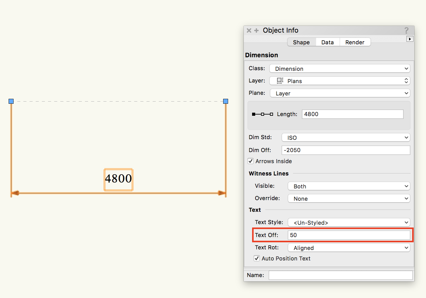
Bruce - why don't you use the text offset setting. They don't have to be exactly on the line do they? You can drag the dimension box to wherever you'd like (off the line), but entering a value in Text Off will keep your dims consistant. EDIT.. Sorry - should have added - Then you don't need a fill to the dimension
-
Why is window ID Tag text flipping to inside when removed from wall?
Gadzooks replied to Christiaan's question in Troubleshooting
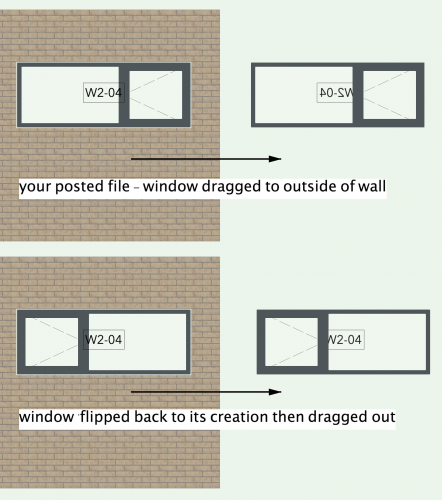
@Christiaan - Agreed, window insertion has 'suck it and see' outcomes half the time. Looking at the file you posted, is there something adding to the 'confusion' VW gets itself into. Your design has the opener on the right hand side of the window in wall elevation. If you look at the window settings VW has your window opening to the left in its front preview pane. If we assume this is how the window was 'created' (and you've flipped the window in this instance) then do a test... Clearly looks like this is a bug if VW can't handle a flipped window style and represent it accurately with ID attached. Could you perhaps try this and just make sure its not me thinking I've stumbled over something, but that turns out I just need another coffee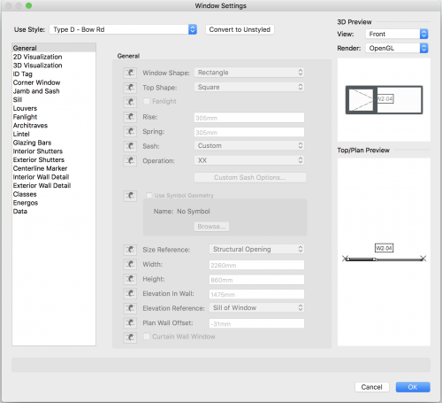
-
(maybe?) I think you have to install incrementally. Starting with the 2017 and then the SP's in turn. Someone will correct me if I'm talking.........
-
Nice little vid @Andy Broomell Sometimes much easier to show than tell.
-
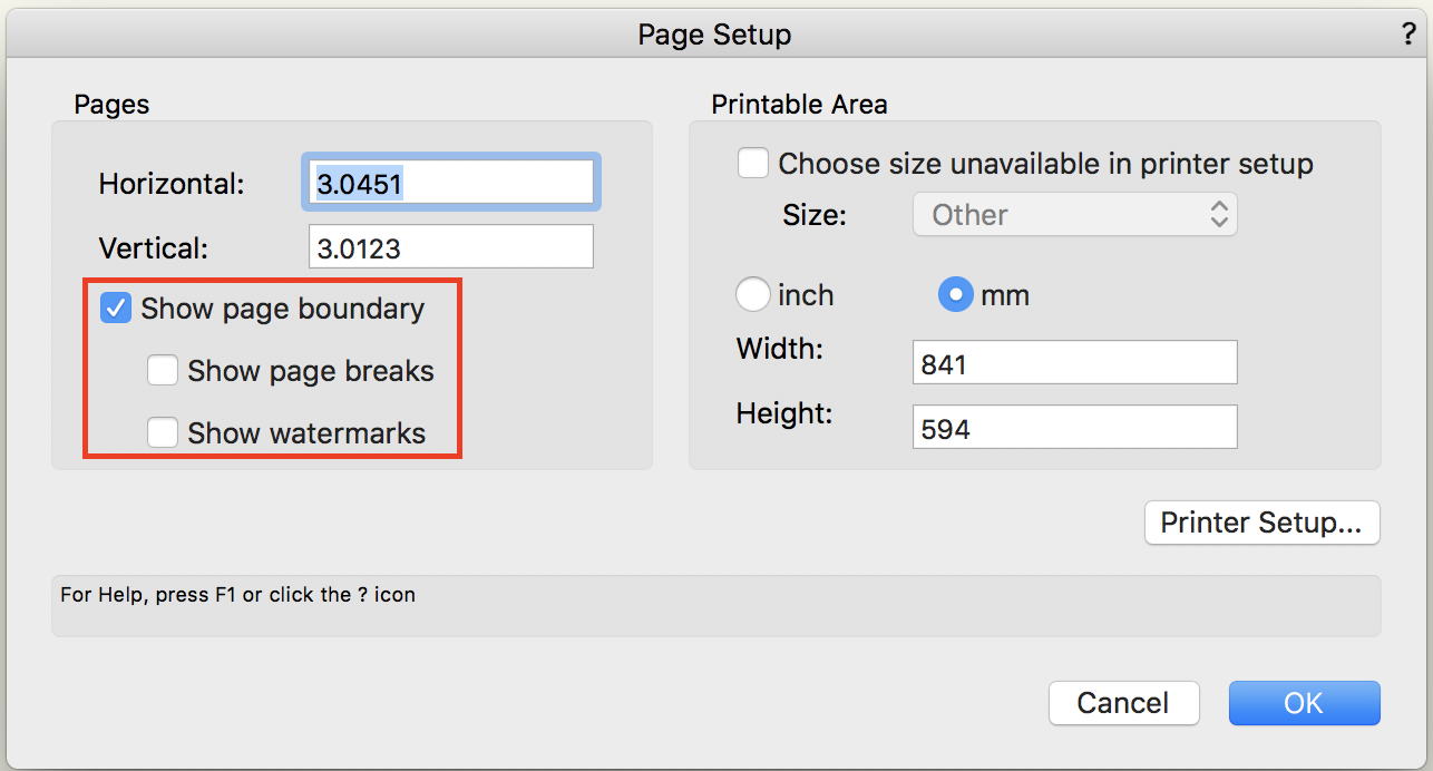
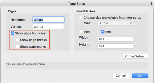
Hi - Have you set the page to be seen? There are options to show in the page setup. You maybe have show boundary unchecked? Edit.. @JimWsnuck-in before me!
-
Good advice Benson. Good and clean control over classes can make or break a project and the way its presented. It's worth time spent on a class 'regime' as it is on setting out layers and VP's.
-
Ha ha. Now I've heard it all. And we (Architect/Designer) moan about it. We should be grateful.
-
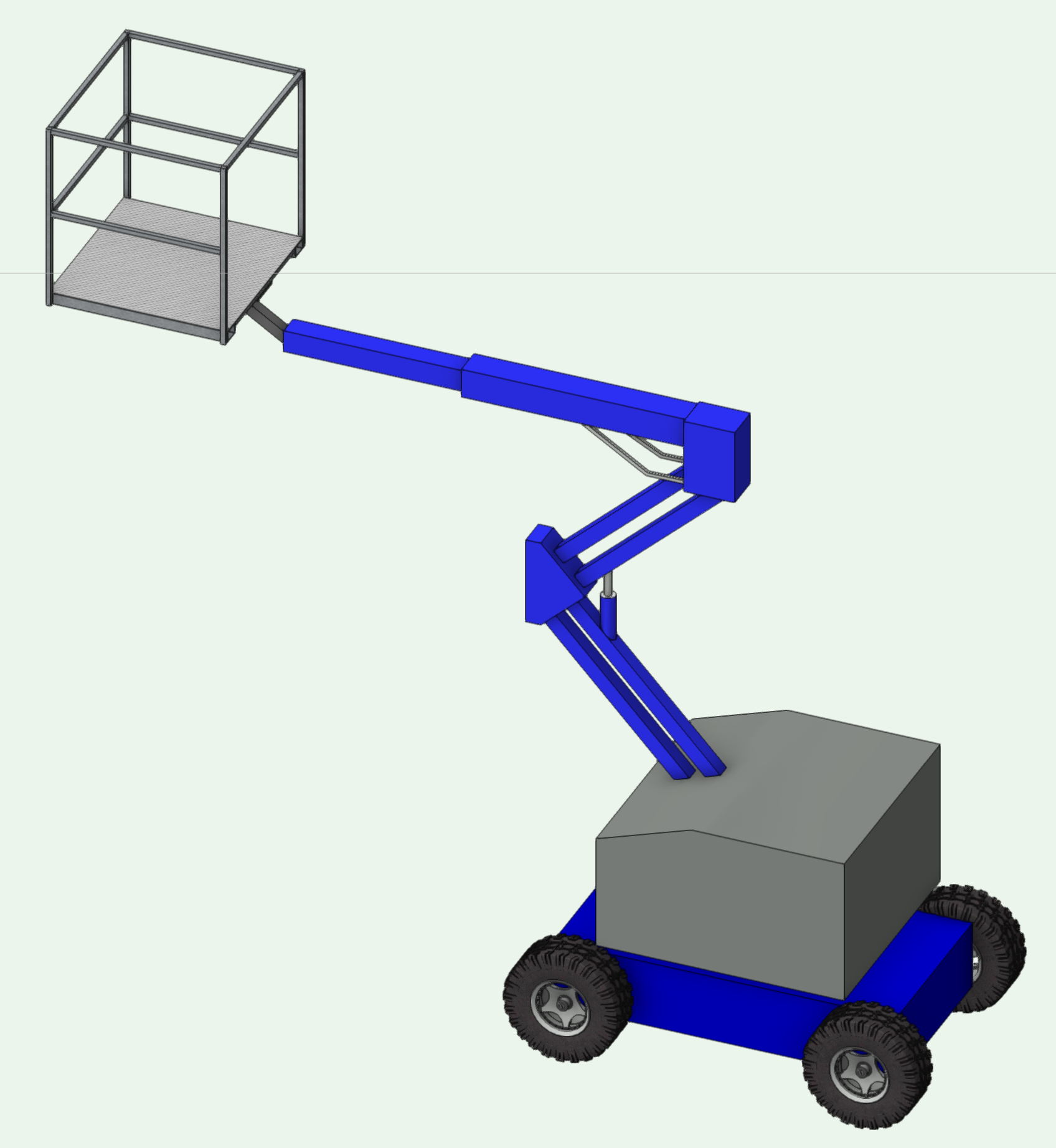
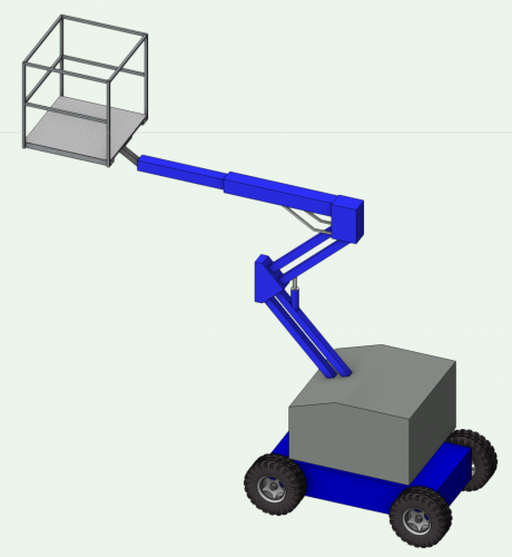
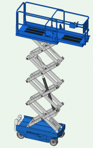
Well I'm not in the market for a lift atm. But I think you need to be quite 'explorative' when you google stuff. If at first you don't get quite what you want it pays to slightly change the search order/question. I've absolutely no idea what you're after in terms of quality/price etc but 3d single man lift gives this.. https://3dwarehouse.sketchup.com/model/u28faf057-bef5-4ce6-a7bd-c5be7b416090/Manlift Would do me - maybe not for you? Change the colour to yellow and stick your client's logo on it Done! Scissor lift gives. https://3dwarehouse.sketchup.com/model/26d1c26917219e40c3513b64581c4322/lift There's loads out there - varying quality etc. "Yer pays yer money (or get it for free) and yer gets yer choice" so there's plenty more I'm sure are better modelled but huge files. Good suggestion - This is always a really good start for 'sublime' or 'ridiculous'. Just spend bit of time looking for either something that is exactly what you want, or something that has potential and you don't mind 'playing' with it to get you where you need to be. Hope thats a start for you.
-
A quick 'google' brings up various 3D models/options. TBH - didn't realise the need for a scissor lift was so diverse and so well catered for!! (Just iching to use one now) Have a look whats out there that will be suitable for your use. Gota love t'interweb.
-
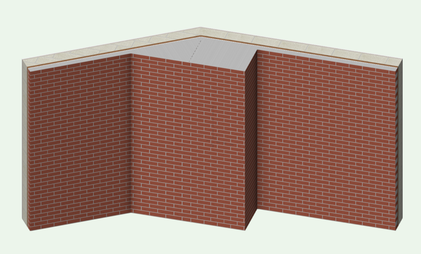
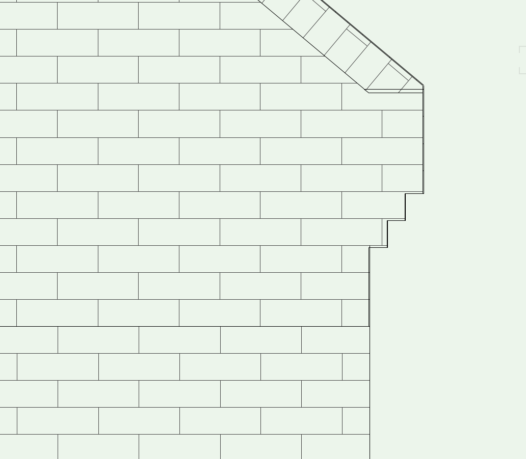
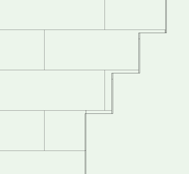
Christiaan - I've looked at this with 'zoom' (I don't usually set that myself - but fair do's, it highlights the problem) If you move the wall away from the auto-hybrid, you will see both objects are given a thicker line perimeter by VW in the hidden line option you've chosen. So thats established its not just the auto-hybrid gable you've drawn. So - start by editing the wall style. In edit you will see the components (and the wall itself) can have pen sizes allocated to it. At the moment they are set to class style. This class size is 0.13 (you can see if you turn the class selection off). As a test, choosing 0.05 will provide a size the same as the brick pattern (To check, if you edit the brick pattern you can see its set to 'draw' in 0.05). If you edit the outer components (these are what VW uses to 'frame' walls in hidden line) to each be drawn in 0.03 it fixes your perimeter problem. I've looked at your auto-hybrid and that also is drawn in the thicker 0.13 pen. Making the same change fixes that (both parts will need changing - the gable and the coping) although the coping looks better untouched in my opinion. A better way must be to change the class style setting itself. But I thought this would provide a better explanation of the reason you have that 'look' and a way to quickly test the modification works. And - making changes like can have unwanted consequences elsewhere. I hope that proves useful - By the sounds of it you may be moving away from this presentation type so the line issue may not be quite so important to fix. (I'm still looking at the corbels construction when I get a moment - this is the face atm - I'm hoping to change that!)
-
Christiaan - (as you've probably decided by now) I don't think VW makes this a very easy process. It's certainly not explained anywhere I looked. However - and someone please correct me if I'm talking ******. When you customise a workspace it saves to your User files rather than the VW application files. When you startup VW it looks to the user folders first. I'd ditch that folder contents. By that I mean do it in a safe 'no harms been done' way by putting the files on the desktop for the moment. You can always put them back if this doesn't work. Then restart VW. VW should warn you it can't find a customised workspace and suggest another. I believe if you've given it no choice other than to choose from the defaults you will find you're back to where you want to be. I've just tried this btw, and it worked for me. (And I've now put my custom ones back - without problem!!) Note: Just as a check to this, look at the file creation dates on the workspaces that are in the Application folders. I believe you will find they have the same (or very close) dates to the release dates of VW versions. Or - they might be modified and be similar to an SP date (where a later SP has released a small change to the workspace.) Hope this works out. ------------- Edit - I should say do this whilst VW is not running - then startup (safer that way)
-
modeling brick side stacks, soldiers, sills and keystones
Gadzooks replied to marshigh's topic in Architecture
Better to see the results following your earlier detailed process. Good job. Well seen through. -
modeling brick side stacks, soldiers, sills and keystones
Gadzooks replied to marshigh's topic in Architecture
Hey @marshigh - would be good to see a few screen shots so we can all admire and make sense of the process you've used. -
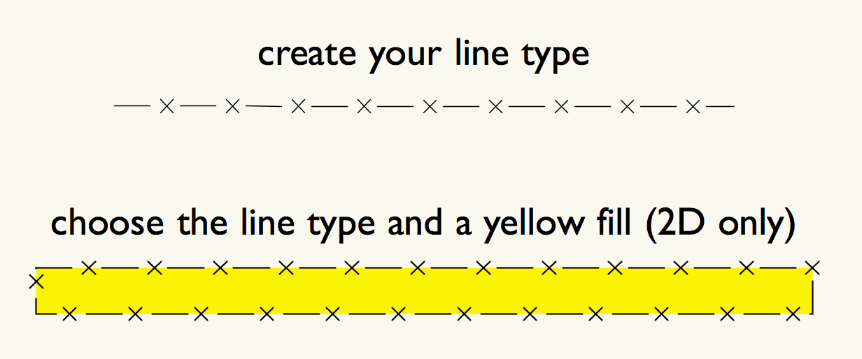
Hi Confurius, You don't say which Vectorworks you are using. This would be good so answers to your questions can be better focussed. Create a signature with the information. If this is a standard requirement in Germany, hard to say why its not a 'localised' addition to your version. Also hard to say why your company hasn't already need to have this line type and someone else has created. It appears you are only wanting to provide a solution for 2D work - is this correct? I'm assuming yes. You are new to Vectorworks you'll find, try as it might, VW can't be all things to all users. You will start to create your own libraries of objects/tools that you find/need to help your own specialist workflow. We all have! Line types will be a good start for your learning . Use the help menu to find how to create a line type that will suit your objective. Save it with a sensible/memorable name and in a library that you'll be able to reference later. It might help for these sorts of drawings that you save it as a .sta file so you always have it available when you start a drawing. (You may have to look up 'save as template' in the help menu) Once created you'll be able to use the line in 2D and 3D. HTH, but (don't shout) better if you find these things yourself as its all part of the learning process. I can post the above line type for you, but it would be good if your next post says you've created one yourself and it works fine.
-
@Marissa Farrell was bound to say that @Kevin McAllister Now we all want what he's having!! Its all hush-hush, but "there's gold in them there hills" when you have the keys to the Vectorworks vault. You right @markdd- obviously being groomed for 'unworldly things' us mortals shouldn't know about. I looked, but I kept my head covered with tinfoil - I'm told thats protected me.
-
Kevin - Thanks for taking a look. I've just checked.. No it persists with the incorrect name. Its only in list view (so thumbnails and thumbnails list show correctly) and I would have thought that was enough of a refresh. However just to solidly check your idea on refresh, I've used both a 'soft' close of the manager (just by moving away from it) and a hard close by dismissing and re-choosing it from the pallets menu (manually or cmd-R). Still there - still a bug! It only happens if you start the duplication (and then naming) process from within list view. Are you not able to replicate then? ----- Edit - extra info Interestingly (or not?) the display panel does show the correct/expected use of -2 etc. so its definitely just the list view pane only
-
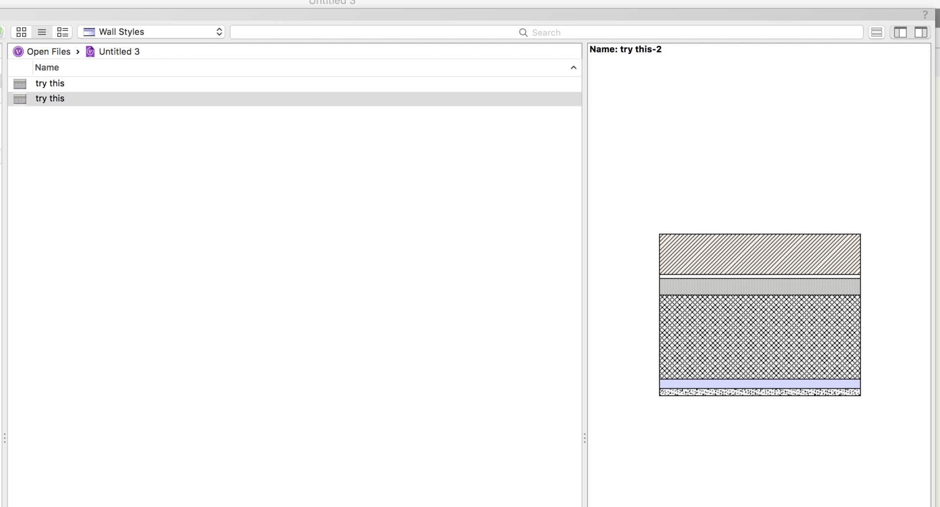
Guys - Minor irritation or bug? I've not seen this on the forum - shout at me if I've missed it being raised already. Open resource manager - you know - the new all singing super-duper one in 2018 (I'm not being too subtle am I?). Btw, I'm on 2018 and yes, SP1. Choose to view resources in list view - it only happens in list view as far as I can see Choose a wall type in the resource manager. (see below - it doesn't seem to mind which resource type) Right click and choose duplicate (standard rename panel opens with the default set to same name with '-2' appended) Type in new name > click OK 'New' wall appears in the resource list with same name as the original - not even with the appended '-2'. Then.... Try to rename this 'new' resource - the rename panel already has your earlier typed name. Click OK and this time its accepted. Additionally (trying to help) The bug even extends to losing the appended number if all you do is accept the default suggestion. In a limited look at this , it extends to all resources. So its a naming bug rather than any problem with resource type. Interestingly - If you switch to another view of the source the 'chosen' name is displayed (so its in there somewhere!). Assume this confirms its list view only. Please vote 'minor irritation' or 'bug' (no hanging chads on this one please)
-
@JimWIsn't there a problem with this, as the wall projection tool doesn't like a shape in the corner (junction in this case) of two wall parts. In my example I had to break it into two pieces - a piece for each wall and then it was happy -------- Edit - you got there before me Andrew.
-
What do you need to achieve Andrew? It looks like your sketch could easily be created as an extrusion as you don't show any components to the 'wall'. Did you actually want to have the wall continue and work as walls do in VW? And, if you will want linked components - is this what you're after? If not, can you explain a little more.
-
Yes, agree Benson. In some ways the hatch is well meaning but too detailed. I believe what's sufficient in hidden-line is an indication of the surface material. Personally, I often choose to show just the horizontals (and verticals for soldier courses etc.) The elevations don't then get tied up with the bricks needing to be shown to be 'bonded' correctly. (Which I think the above exercise has proved to be quite difficult at times). More like the hand drawn detail we would provide years ago. (Yes, I remember!). The elevations can be 'knocked back' by using a grey rather than black pen for the hatch and even to use a degree of sketch to move towards a hand finished look.
-
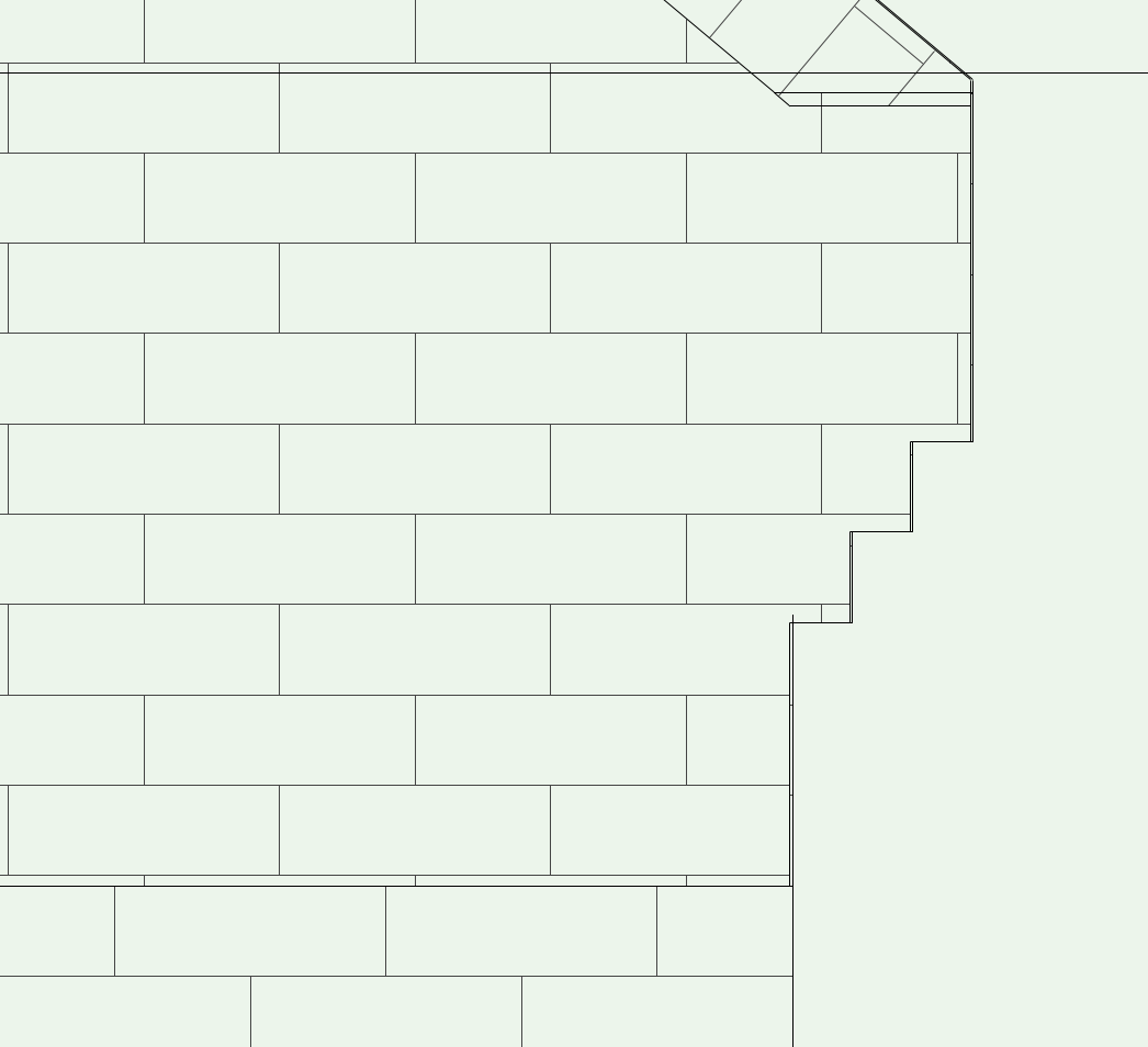
Hi Christiaan - Looks simple? It isn't. - This problem has more layers than a black forest gateaux. (must be time for tea). This is worth cracking, as this type of detail is often used. So I'm still having a play with your files to see if there's a more satisfactory way of forming your corbels, but for the moment I think your 'line' on the first screenshot is merely a mis-alignment of the hidden line texture. If you pan in close (no - closer than that!) you can see a few mm out. If you re-register (zero'ed to the base of the extrude/auto hybrid) the texture refreshes correctly as you would want. Yes - definitely would help this situation, but nevertheless, having arrived by the 'long-hand' method available this also somewhat corrects the brick bond (left to right) - but I've noticed your corbel construction starts with three courses of brickwork which should be 225 high in round terms whereas you have 218.63mm (on your uploaded file). I know this is picky, but the texture starts to drift. Hope this might help for the moment.
-
Tom, Weird - sorry, I can't replicate that. Mine defaults to 2" using a 'fresh' file.