
mgries
-
Posts
135 -
Joined
-
Last visited
Content Type
Profiles
Forums
Events
Articles
Marionette
Store
Everything posted by mgries
-
OMG...Is THAT what's going on?! Thank you for clearing this up for me! I had learned that setting class to "none" inside a symbol allows the overall symbol class to control display. But often this does not work. Now I know why... Honestly, this really needs to be fixed! It is far too often the case to have some text inside a symbol set to a separate "...IDEN" class, so the text can be turned on or off separate from the linework. This shouldn't get in the way of using the "'none' class gets overwritten by symbol class attributes" rule. Matt
-
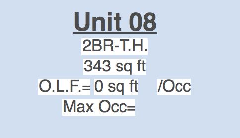
I'm getting a new problem related to Space Tool upgrade. I'm using the old version space labels in which I've created some sub-classes for the text. This allows me to independently turn on/off extra data about the space (such as the Area, Room Dimensions, or Occupant Load). In the screenshot I've attached, for example, only the top 2 lines of text are on the none class. The last 3 lines of text are on unique IDEN-DAT1,2,...etc. classes. After updating to SP3, all of the space label text is permanently displaying regardless of on/off visibility of these sub-classes. Is this supposed to work this way now? This had been a very simple and consistent way for me to control label info. Please help! This has wrecked my drawings! thanks, Matt
-
Is it a known issue that hidden line sketch mode (I'm using Section viewports in this case), produces seriously unstable results? I've run into a few different ways it fails to draw the expected result: The most common issue is that it displays everything in the view, but sketch mode does not appear to be activated. In some cases, the line work initially displays in sketch mode, but then after drawing annotation in the viewport, sketch gets deactivated. To be clear, sketch is still checked off as the desired render option, but the viewport behaves as if it's been turned off. Other times, all of the lines "beyond cut plane" simply don't display at all. Silver lining here is that for whatever reason, this seems to reactivate sketch mode for the cut plane elements and the annotation. There's also cases where the model line work maintains sketch display, but the annotative layer displays without sketch. I've also gotten the reverse situation, where only the annotation was displaying in sketch! It's really all over the map. There does seem to be one way to control this situation (at least it's worked so far). I discovered that by setting the line style of objects beyond cut plane to "use original" in the advanced properties, I can stabilize the sketch render setting, and both model and annotation maintain the correct display. When this is overwritten with a single class, all bets are off. Unfortunately, using the original line style of each modeling object requires a lot more work than being able to quickly set all lines to the same weight. So this is an unfortunate work around to have to accept. Thanks, Matt
-
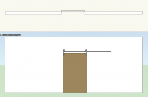 This is a great tool @sbarrett! The major drawback, unfortunately, is that there's no way to style the door. What happens when you move this into design development, and need to represent the door as a specific style? Would it be too much to add a few simple style options to this tool? Thanks, Matt
 -
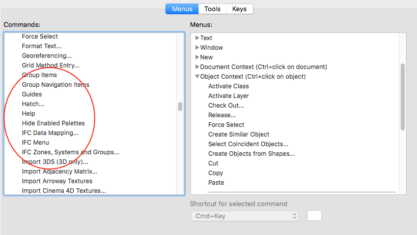
I saw this thread, and didn't know about this command. I went to add it to my workspace, but I don't see it! Is the name of the command something other than "Hide Objects"?

-
@sbarrett, could this be reworked so that the "A" polygons were on one design layer named "A", and the "B" polygons were a second design layer named "B", and then the resultant geometry gets placed on a 3rd layer? I'm thinking about how this may be applicable to creating and defining exst/demo/new surface areas on a site plan. Thanks, Matt
-
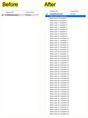 You were right, my spaces didn't have room numbers. After assigning room numbers, separate sheets are being created from the script. I'm getting closer to the goal! I wish I understood this whole marionette business better...i definitely need to watch some tutorials. It doesn't help that I also don't know anything about scripting. I'm still unable to correctly control layer visibility in the 1:50 viewport. When I uncheck "show all layers", it still turns on multiple layers (just not all of them). How do I make sure only the layer that the space belongs to is visible in the viewport? Also, would this marionette work equally well with Detail Viewports? Could it be configured so that the bounding box was turned into a Detail Callout Marker? If that could be achieved, this marionette would be perfect for generating Enlarged Plans.
 -
Thanks Dom, Yeah, looks like all my handles are the same (or at least most of them). In your file, they're all different. How do I create unique layer output handles for each space?
-
Hi Dom, I tried this out on one of my files, and changed the criteria of the first node accordingly. When I run the script, ALL the viewports of the spaces show up on a single sheet layer, stacked on to of each other, instead of being distributed among multiple sheets. Also, ALL the design layers are on in all the space viewports. For the overall plan (reference) viewport, the correct design layer (only) is displayed. Any clue what's going on? Matt
-

Successful strategies for reference grids/planes in 3D
mgries replied to line-weight's topic in General Discussion
I like how this method ensures that the benchmark gridline updates with any changes to story/level data. That's pretty smart. Regarding issue with graphics, it's already very easy to apply the benchmark elevation tool directly to the annotative layer of the Section viewport. Why not just have the grid datum slab in the model w/o the anno, and apply the anno in the viewports as necessary? This carries with it the same benefit as with the data tag trick. You get to put the tag wherever it's needed. If you put it in the model, it's stuck in one location, and is only really useful for the full view drawings. You'll have to re-annotate your benchmarks for any enlarged or partial (cropped) drawings. matt -
Successful strategies for reference grids/planes in 3D
mgries replied to line-weight's topic in General Discussion
what I really love about this (in addition to providing gridlines for sections and elevations) is that it solves the problem of noting gridlines in enlarged drawings. Currently, we create 4 extra viewports (surrounding the main enlarged plan viewport) as a way to pull the grid tags in close to the cropped drawing area. This can really save some time! -
Successful strategies for reference grids/planes in 3D
mgries replied to line-weight's topic in General Discussion
This is FANTASTIC! It works! I'm calling this the gridtangle tool! one question, what extra "enhancements" are you getting from classing the horizontal and vertical gridlines? Is this so you can prevent a horizontal line from appearing in the section cut if you crop above or below the extent of the gridtangle? -
there are a lot of changes to 2019 that will most definitely make you have to start your table all over again.
-
Yes, i agree with your assessment of top-plan view. It seems like it might be slowly going away. Looking at the advancements to symbols in 2019 (2D views), including more control using detail levels, it's more about individual elements having their own planar display settings, which could be paving the way to eliminating a global top/plan paradigm in favor of a 3D model paradigm (w/ object based 2D view overrides). AutoCAD was more like this, and I must admit that customizing display properties for every little thing was quite overwhelming
-
wow...feeling pretty dumb about now. yes, that was the issue thanks!
-
@Pat Stanford, you can add =AREA to this list! After reporting my bug, tech wrote back to let me know they're on the case. They also offered a few alternatives to try, one of which was "=AREA". Works like a charm!
-
I know this is a bit of a tangent, but I'm having problems in 2019 with my drawing label, and can't find any thread on the forum directly discussing it. My drawing labels aren't synching to the viewport OIP fields anymore. I have to go into the annotative layer and edit the information directly. This is occurring on viewports where the drawing label is created automatically, which prior to 2019, always synched up with the Drawing Title and Drawing Number OIP fields. Is anyone else experiencing this? thanks! Matt
-
I'm kind of liking line-weight's direction... I think if you peel this onion away enough, you'll come to the brave conclusion often voiced throughout this forum, and that's the need to do away with design layers altogether. A pure BIM experience really only needs: stories (available) horizontal section and cut planes (the later just being the story default setting for the former) (available) option to view a set distance (# of stories) below the cut plane. (available) option to to configure the horizontal section at the cut plane as a Top/Plan view. (available?) option to control display of cut plane classes and display of beyond classes separately (available) option to control display of beyond classes in their own Top/Plan representational mode. (not available) I haven't messed around with the horizontal section yet, but from what I understand, the functions represented by 1-5 are currently available? Actually, I'm not sure about #4. Can the horizontal section be viewed in Top/Plan mode at the cut plane? Am I wrong in suggesting that all of these display issues might be a bit simpler to control if we didn't have to deal with the merging of two somewhat redundant organizational/display paradigms? Matt
-
yup, Using the factor 92903.384, I can get all the correct areas to show up. I need to revise my initial statement though. It's not precisely 92903.384. The corrected values are only correct to the 1/100th decimal place. But to your point, whatever the fudge factor is, it seems to be consistent for all values.
-
Pat, although this number is close, the values are getting multiplied by precisely 92903.384. There must be a little something else at work.
-
This issue has always bothered me. When all the good options are work arounds, especially work arounds that require redundancy (duplicate classes, stacked viewports), things are going to get sticky. I've used both strategies, and in an office with multiple users, it's inevitable that someone else will mess up your stacking order, or delete one of the viewports, or not know to turn off/on sub-classes. They'll hate you. You'll hate them. Eventually, someone will eat your food in the fridge. Was it an accident? You'll never know for sure... It's better if we just get the software right!
-
Thanks @Pat Stanford, Here you go! The file contains a single space and a worksheet. %22Space Area Number%22 function incorrectly reporting.vwx
-
No, I'm still stuck with this. The document area units are set to sqft. Also realize that when using 'Space'.'11_Area', the area is reporting correct. So the units don't seem to be the issue. It's only when using 'Space'.'Area' that everything it goes haywire.
-
@cberg and @Jim Wilson Does this bug fix also address the issue where the spaces all get reset to the style default info, whenever an existing space is switched to that style? I'm having this issue (and some similar style related implosions) too. Thanks, Matt