nahekul
-
Posts
57 -
Joined
-
Last visited
Recent Profile Visitors
2,550 profile views


-
If you clear the content of those new database header rows, and now try to copy the first row into those empty database header rows, it will start offsetting.
-
It works correctly if you copy it to a new empty cell. It doesn't work if you copy it to an existing database header cell.
-
Here's a screen recording. test.mov
-
Here's the file. I am just copying the one database header row and pasting it into another (blank) database header row that's already created. test 1.vwx
-
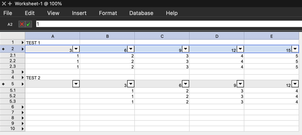
I'm clicking on the "2", which auto-selects the entire row. (Not by selecting all the cells.) There are no merged cells in the worksheet. This is done with a new worksheet and converting row 2 and row 5 to a database row.
-
When copying one database header row to another row, the data in the columns are shifted to the right by one row. See the image: - Row 2 is copied/pasted to row 5 using cmd+c and cmd+v - Data from column A is shifted to B, B -> C, etc... However, if the row is copied by option dragging, then the columns stay in place.
-
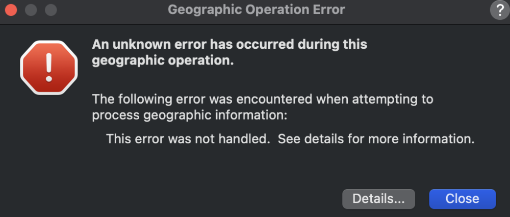
This doesn't seem to work for Vectorworks 2023 and 2024 now. When importing the ECW file, even with the all-files option selected, it gives an error.
-
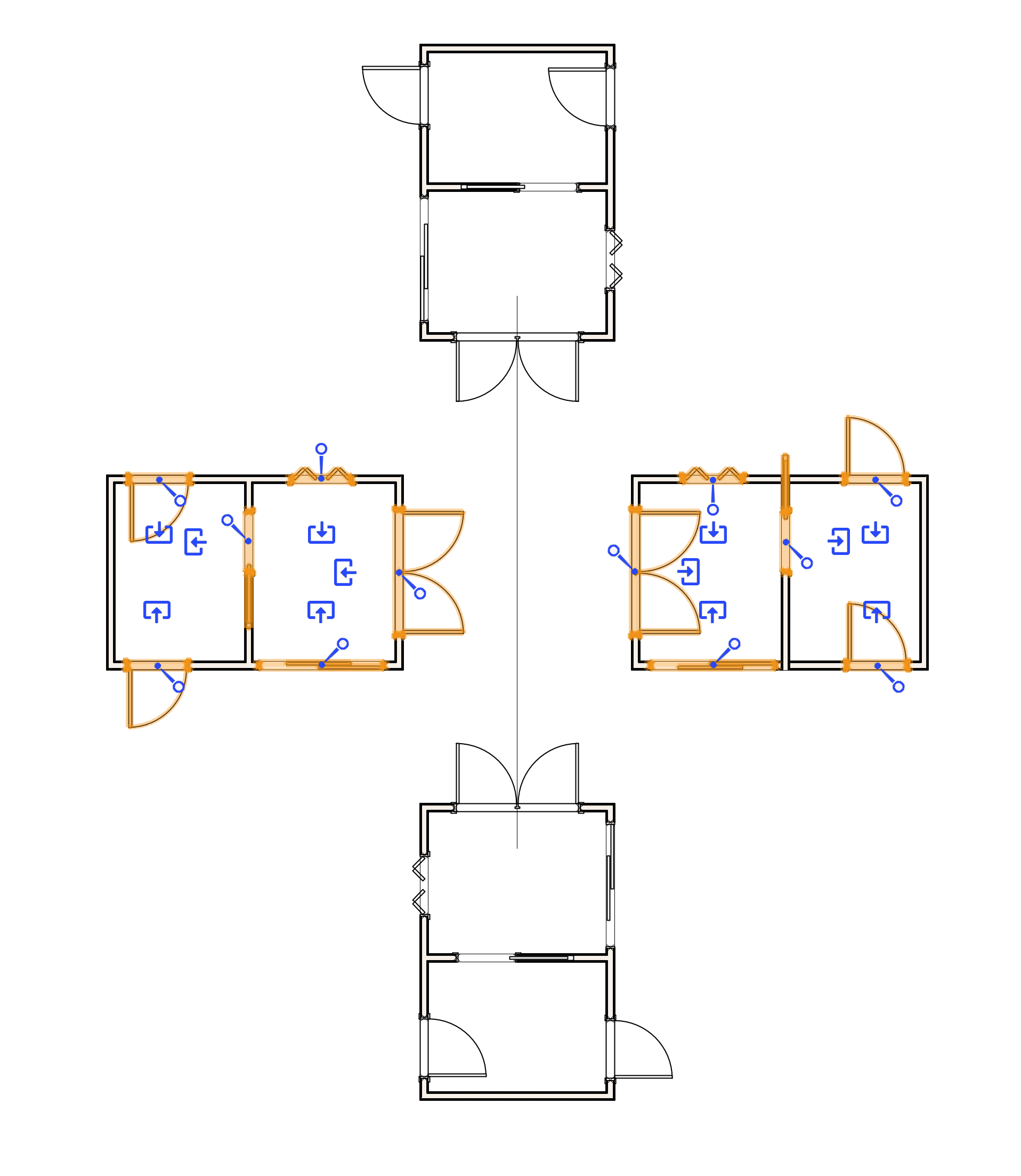
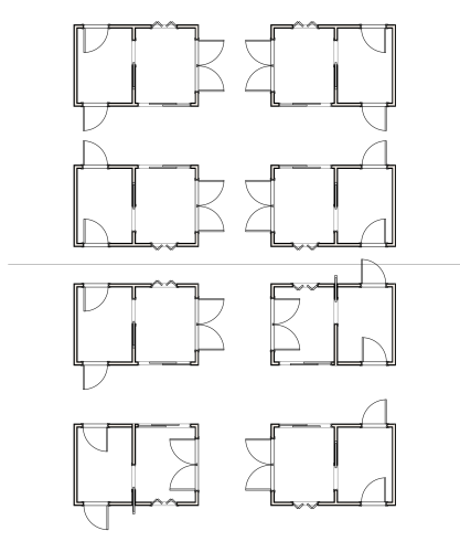
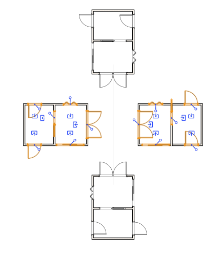
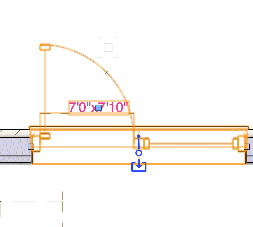
When flipping or mirroring doors that are inserted into walls, the program seems to reverse the direction of the doors but the handing remains the same. For example, the outward swinging door still says out but the graphics is showing the reverse. However, rotating them seems to maintain the correct door orientation and graphics. Flipping/Mirroring works in symbols. However, once the symbol is exploded, the doors are reverted to the incorrect orientation. Interestingly, only the symbols that were supposed to be flipped are messed up (top right and lower left). The lower right one is correct. (I assume that even though it was flipped, that orientation was achievable through rotation so it is not messed up).
-
VWX 2024 - Interactive handing and flipping of Custom Windows
nahekul replied to nahekul's topic in General Discussion
This looks to be resolved by editing the style, changing the configuration to "by instance" and then changing back to "by style". After that, replacing the 2 different styles will change the window's operable sides. -
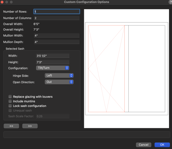
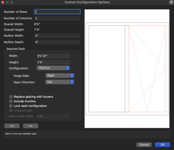
With the update of 2024, the new feature of interactive handing was added. This works well with the standard configurations but I can't figure out how to get it to work with custom windows with a center mullion. In 2023, I can set up the custom window and flip the operable side to the left or right. In 2024, the operable side only stays on one side and I cannot flip it to the other side. Even making 2 window styles, one with operable left and one with operable right, it does not show correctly once inserted into the wall.
-
VWX 2024 Railing tool missing custom symbols for post/brackets
nahekul replied to nahekul's topic in General Discussion
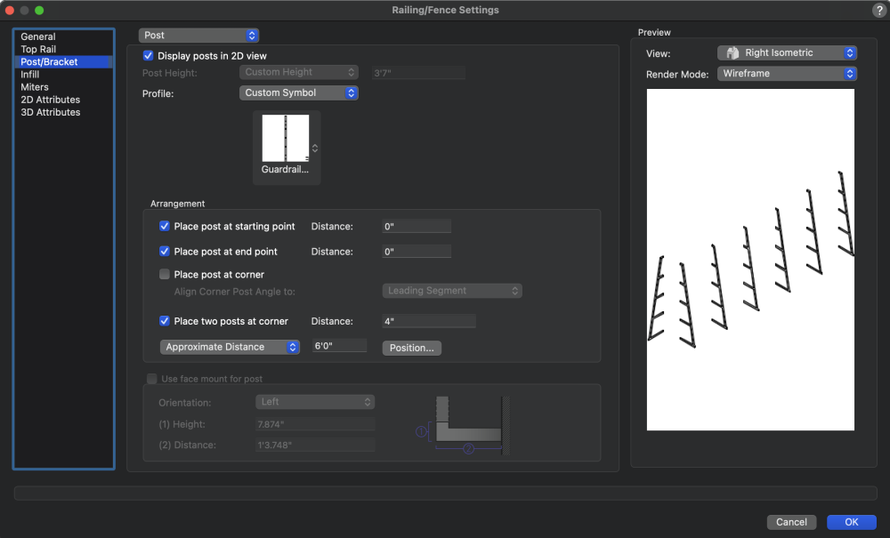
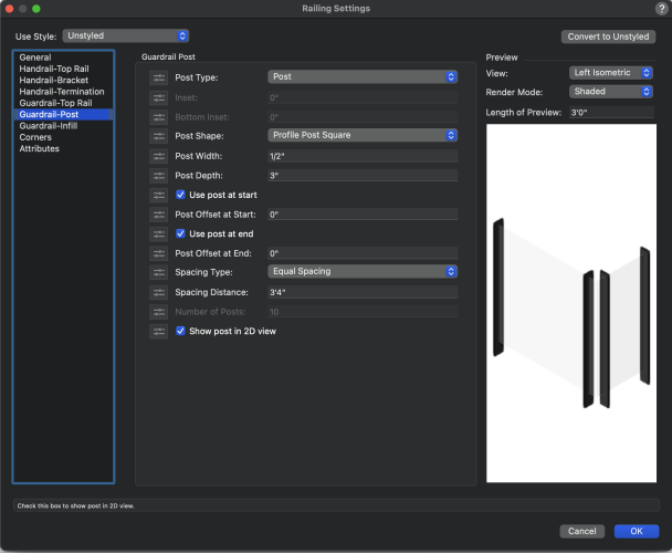
It allows me to select the 3D custom symbol and the preview shows the selected symbol but does not actually apply it outside the settings. Also, it seems like there is no way to turn off the infill. -
The new railing tool seems to be missing the option to use custom symbol as the post/bracket profile. Without this, there is no way to have any railing that is not just a straight extrusion. (eg. belly railing or angled railing) Will this feature be added back to the new railing tool? Old Railing Tool: New Railing Tool:
-
You are correct. I must have misremembered how this works before. Exporting doesn't work for saved views when I try to select it. The only way this works is to go to each saved view and export it manually using design layers.
-
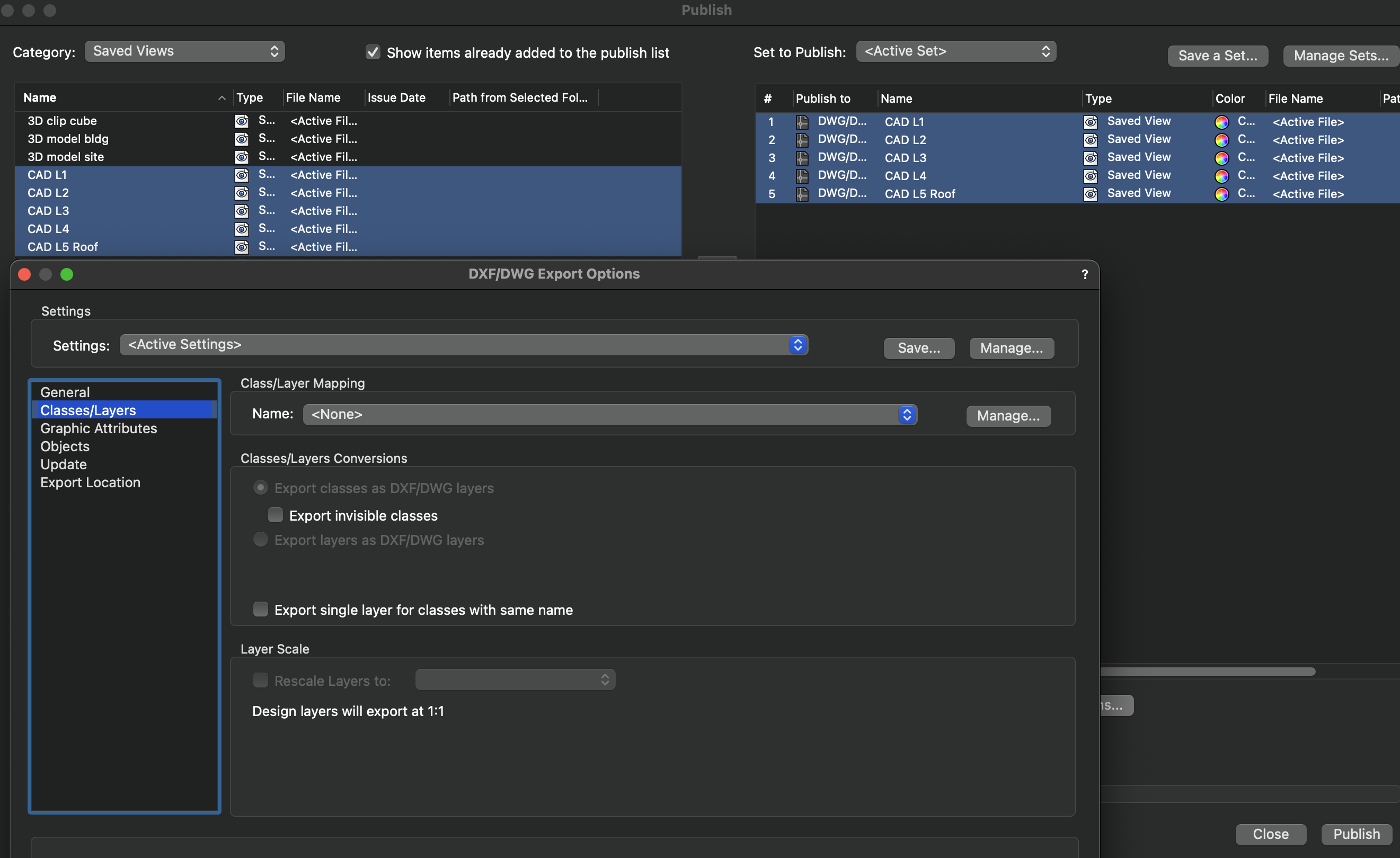
It's when I try to publish saved views. (Using File>Publish) However, when I export the saved views individually it works. (Using File>Export)

-
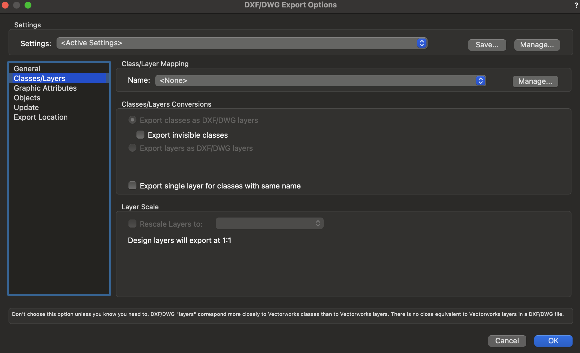
How come "export layers as DXF/DWG layers" is grayed out now? We used to be able to select that option.