halfcoupler
-
Posts
461 -
Joined
-
Last visited
Content Type
Profiles
Forums
Events
Articles
Marionette
Store
Everything posted by halfcoupler
-
Maybe this helps: You can find some XLR sockets in: Vectorworks Libraries /Objects - Ent Controls / zNested Parts.
-
Solid subtractions often fail when the solid parts overlap in a complicated way. This can be very small parts, often overseen unless you zoom very close. You can try to add the solids instead of subtract and you may find intersecting edges and lines in places where you do not expect them. That is where you have to edit the geometry. If you have more than one solid to subtract you can also try to subtract one by one. b.t.w.: Worked with this microphone when I started my business around 1985.... Seems I'm getting old ... 😉
-

Navigation with 3Dconnexion SpaceMouse
halfcoupler replied to hollister design Studio's topic in General Discussion
I'm using this workaround: - activate the flyover tool - use Object center mode - select an object and move it a bit via the flyover tool. After that, the space mouse will use this object as center. Not really a smooth working process, but it helps with big drawings when the space mouse bumps the plan uncontrollably around because the rotation center is somewhere at the other end of the drawing. Worked in VW 2020 and 2021, with the last two 3D connection drivers. -
just an idea: - for colors and textures you could use data visualization, this overrides the attributes based on data and you do not need to touch the objects. - another possibility would be to use symbols or nested symbols. You could define your wall as symbol and lock it and then do the changes via 3D component of the wall symbol in the recource manager without touching the drawing itself.
-
Yes, that's it ! Thank You 😀
-
Hi, maybe anyone here can tell me why this is not working? Procedure CustTool1; VAR Name:STRING; Result:BOOLEAN; BEGIN PushAttrs; CallToolWithMode(-209,1,3); PopAttrs; END; Run(CustTool1); I simply want to call the Insert Symbol Tool with pick up option. This script calls the tool in the correct mode but I cant select a symbol in the drawing.
-
Yes, I always have the same thoughts, but the solution seems not to be trivial: Which is the correct height ? Is it the height if the bounding box ? Or the average height of the containing objects, or the max/min height of the objects ? Anyway, it would be great to have at least one fixed point in th OIP, so movements relatively to that point can be made. But when you want to have a tool to align several different objects including groups in 3D, this will result in an "options monster" and it will be simplier to use the workaround with the 3D locus.
-
Is it correct that detail components with level "high" inside symbols are generally ingnored in thumbnail views in the resource browser ? I have nested symbols with detail components leve "high" only, which results in an empty thumbnail.... Looks a bit confusing ...
-
maybe anyone here knows why this happens ? - draw a rectangle with fill - set a 2d locus as sweep point - select both - do the Model/Sweep command - as Parameters set the pitch identical to height (which is the rectangles height) - Start angle 0,000 - sweep angle 360,000 - press enter => a spiral object with a 360degree turn is generated, as expected. - select the object - do the Modify/Convert/Convert to Generic Solid command => the object dissapears. This happens only when pitch is identical to height
-
yes, works as desired in 2021
-
precisely 🙂
-
hm, that file is already a great design for the new poster, but I would definitely change the text attributes to pen = black, this will suite best to the current situation. 🙂
-
What I learned: (left side) - Grand Canyon can't be rendered, nature is too ingeniuos to put all this into small triangles. What I knew before: (right side) - As I always tell my fellow collegues in the entertainment industry (especically in these times): From a governmental view, the safest event is always the one that does not take place. ...keep safe, but not safest. 🙂
-
Just tested this, and it is really a great time saver, but I stumbled over this: - create an object with modeling history on one layer - select it and choose "Edit Features" with right mouse click - click on an element to change - do some changes - exit with Modify/Top Level - set the Layer to invisible => the object remains visible on all other layers as an non selectable artefact unless you close and reopen the file maybe someone can retrace this, so I know its not my machine ?
-
Viewport Bounding Box is Larger than the Viewed Area
halfcoupler replied to MTRobin's topic in General Discussion
stray objects could also be 2D objects that are not shown because "display planar objects", "project screen objects" or "display 2D componets" is turned off in the viewport. I have this very often and always found the reason for this big bounding box are stray objects. My only solution ist to switch off class by class and layer by layer to see where the objects could be located. -
hey, you are my hero !!! it has nothing to do with workspaces or settings, you are right it was simply rezized ! Everything fine again ! I will make a tomato salad today ... 😀
-
Somehow I have deactivated the editing Buttons in the Data Tab of the OIP in my workspace. "Attach Record" "Attach IFC" and "Detach" have dissapeared in this workspace. Everything works fine again when I recall the standard workspace. I'm looking for hours now to find out which setting I changed, but there is only tomatoes on my eyes.. Anyone here who can give me a hint ? 😵
-
Hi Art V, thank you much for the reply, in the meantime I found similar answers: 3D PDF seems not to be invented for backwards compatibility. Anyway, there must have been a CAD file prior to the 3D PDF from which it was exported. So it ends up to me to ask my clients to send me either 2D PDF or .dwg format out ouf this original file. In the end 3D PDF is only for viewing, but not for working with 3D Geometry.
-
If I see right, there is no way to import 3D PDF's directly to VW ? I'm getting more and more of these "plaything files" from clients and wonder if someone here has a solution for the quickest way to get a Top, Front, and Sideview out of these files into VW ?
-
Hello Marissa, thank you for helping :-) here is the example. (It is part of a larger Marionette network, the mirror points are sample points) I have made a Menue Command from this wrapper. Once the object is mirrored, the command can not be executed again since the object is already marked as mirrored. (Using the "Get 3D Orientation" Node shows that the value "bMirroredXY" is "True") What I want in the end is that the object is mirrored again every time I run the command. Is there a way to manipulate the object so that "bMirroredXV" is set back to "False" ? Mirror.vwx When doing a mirroring manually there is no limit to the numbers of mirroring. Maybe I'm wrong when I expect the Marionette nodes should work similar to hand drawing ?
-
It seems that the Mirror Node does not work on an object that is already mirrored. Is there a way to "un-mirror" it ?
-
All the world's a stage, And all the men and women merely players; The Prologue: We are rapidly reaching 100 days that covid 19 has totally killed the entertainment industry. My personal feelings on this can not be better described as that in E.A.Poe's "The Pit and the Pendulum", where you get thrown into a dark pit, bound to a torture table, visualizing that the razor-sharp pendulum that swings above your body is moving down little by litte with every heartbeat you have left. You know that the death you are expecting is unavoidable and that you will feel the pendulum slowly but stealthily slice into your guts cutting your body into half in a long and painful process. What E.A.Poe could not have known when he wrote his story, is that a 180 years later the black thoughts you have in the pit are interrupted by a daily pling that reminds you that you have new mails on the discussion about the vectorworks tool icons. The Play: So I consider myself as a man of practice and ignore that stupid pendulum happily swingigng above me with a sarcastic grin, while doing my personal summary on these icons: - they look childish - they are not distinct - they are confusing It's a bit like you are an actor on open stage when you can't remember your text. You feel that the audience will laugh at you since you don't look professional in this situation. To avoid this situation there are a three things to do: 1.) learn your text. (=> learn your shortcuts, I totally argee with @RussU, who already mentioned this in this thread) 2.) play as a professional actor. (=> auditions with your client are nothing else than a big theatre play, only the result matters. If you can bring your audience to laugh or be impressed then you have won, no matter what means you used to achieve that.) I think this thought was also already mentioned here. 3.) make alternative text that you can use in such a situation until your brains are back in place and you can proceed.(=> create workarounds) Points one and two are no software skills, but for point three I want to present my personal solution. Although it is generally not recommended to mix up your workspace too much I did the following: - All tool palettes shown as "Icons and Text" (I admit, only suitable with two monitors and enogh space for the palettes) - Remove all tools that you are 100% save using with shortcuts from the palettes or move them to the end of the list if you have enough space. A shorter list can be better gathered at a glance. - In the workspace editor sort the tools alphabetically. After a while you will automatically search A,B,C tools at he beginning of the list and S,T,U tools at the end. You will find that you will not look at icons, since you won't need them to find your tool in the list. Maybe someone will find this useful. The Epilogue: No question, the GUI has to be overworked. No reason why windows users should be excluded from "dark mode" and additionally be punished with these icons, forced to make workarounds which is not their original job. But I think this thread is long enough that the developers have learned their lession. I am shure they already work hard on this unspeakable icon thing, bringing us some solution some day. So what do we do in meantime, while being forced to stare into the ceiling at this fateful pendulum? I am at a loss with that. While browsing youtube for tutorials and clips for improving my VW skills in the meantime I stumbled over this video. Looking at Larkin Poynton's masterpiece of choreography to Benjamin Clementine's crying out "I Won't Complain !" it triggered my deep craving for theatre, dance and culture. I'm starving to lean back again into a theatre seat, enjoying the show with hundreds of fellow visitors, pushing all icon problems away like a highwind in jamaica. But No, Oh No, No, No, I wont't complain !
-
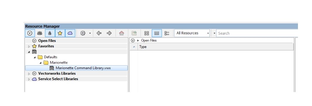
Hi Pat, maybe I was not clear enough: I dont want to edit Marionette Nodes, I want to edit Marionette Commands as is described in the help file What puzzles me is "If the wrapper node is not in the drawing, the wrapper node resource can be imported from the Marionette Command Library file in the Resource Manager." but I can`t access this file from the Resource Manager.
-
as described in the help files marionette commands can only be edited in the user/libraries/defaults/Marionette/Marionette Command Library.vwx file. in my resource browser I see the following: This file can not be opened from the resource browser, and there are no resources shown. I can only directly open it when navigating to it via explorer. Whats strange: I can't simply open the 2D symbol definition here, edit the Marionette and save the file. This has no effect on the Marionette commands. I can only open the the symbol, copy the marionette, paste it somewhere, edit it, wrap it, create a menue command and overwrite the old one by choosing the same command name. Is that correct, or is there a more elegant way to edit marionette commands ?

-
Great ! Works perfect. Thank You !