-
Posts
3,755 -
Joined
-
Last visited
Content Type
Profiles
Forums
Events
Articles
Marionette
Store
Everything posted by line-weight
-
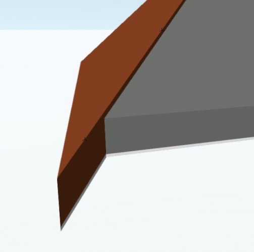
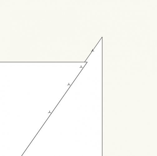
I've got two roof faces which meet each other at a vertical join. If I look at them in 3d, I can see that the 'inner' faces are aligned at the join, but the 'outer' faces aren't. This is because the two roof faces are at different pitches. (Am I correct to understand that the reason they are aligned on the inner face is because this is where I have set the "datum" for the components on each?) But when I look at this in top-plan view, they are drawn as if they are overlapping. Why is this? You can see that I have placed a few 3d locii to check that the "join" face is vertical. You can see them in the top-plan view. I've attached the VWX file. roofsvw.vwx
-
I think I mostly understood about how you draw them - thanks - so there is no need to make a video, although it might still be interesting to see. With the classes (actually it may not be related to textures as such) - the specific thing I noticed was: 1. Viewing in OpenGL with "use textures" and "use colours". 2. I assign a "material" class to each component, and each class has its own "fill colour". 3. I then edited one of these classes, to change it's "fill colour". 4. Then, viewing in OpenGL something strange was happening, the relevant component would sometimes appear with its "old" colour and sometimes with its "new" one. It would change when I shifted the view around. 5. Changing the render setting for the roof face object from 'by component' to 'by object' and then back to 'by component' seemed to fix it.
-
I'm having problems with this too. When I select the clipped roof object, "edit group" is greyed out in the menu.
-
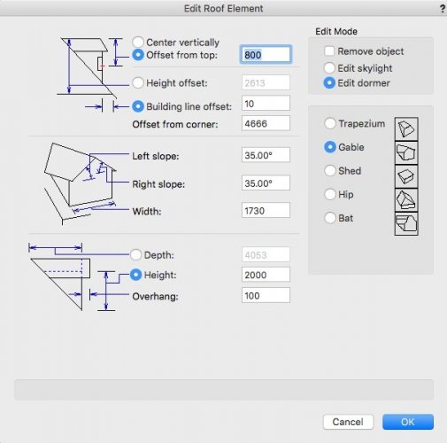
Yes, having tried the dormer tool out a bit more now, I've decided it's not all that much use, except maybe if you want to show something indicative at an early stage. - as far as I can see, you can't go back and edit the window easily, because although it exists as a symbol, it's no longer a plug in object so you can't make adjustments to it in the same way that you would to a normal window-in wall - it seems that the only way you can adjust its location in plan is through typing numbers into the dialogue box in a trial-and-error kind of fashion, which isn't even updated live, so you have to keep closing and opening the dialogue to see if you have got it right yet - the controls themselves seem rather confusing, with various options to offset and so on, but little information about where the reference points actually are, how they relate to what points on the symbol, and so on. Even roofs/roof faces themselves (which I've not used a lot until now, but they do seem useful to an extent) are a typical VW jumble of confusing, inconsistent and anti-intuitive commands. And something weird seems to go on with textures and classing by component and so on.
-
When you get into the edit dialogue for the dormer/skylight, in the top right you can choose between dormer and skylight. It's not well worded - "edit dormer" implies it's a function to edit an existing dormer whereas really it should say "create dormer".
-
I just tried creating a dormer window for the first time. I've not tried using this before. I ran into exactly the same problem as @domer1322 above. I followed all the instructions, including the create a symbol bit, which isn't properly explained in the user guides, and activated the symbol, and tried to insert it into a roof face. Nothing. I remembered this thread. So, reading it, yes, you have to *drag* the symbol from the resource browser. As identified above. But not stated in the VW documentation. Thank you @domer1322. It's absolutely dreadful, this. How to annoy and frustrate your users, for no apparent reason. It should win some kind of award for terrible design.
-
No word on this from anyone at VW?
-

Thanks for making computer work fun again!
line-weight replied to Jeff Prince's topic in General Discussion
Another thing that is a bit of an art ... and especially when you work in 3d. You measure the ground floor and the upper floor, and drawing each one individually all works fine. Then you overlay them and it doesn't. In 2d you could to some extent pretend it wasn't happening. Maybe you would bodge things around so that at east the staircase makes sense. If the proposed work didn't involve connecting the two levels in new places... it didn't matter too much that the chimneybreast on one level was 100mm away from the one below. Can't really get away with that in 3d. It'll show on the elevations at least. So you have to do a bit of "rounding", and decide which dimensions are the important ones, which might be the ones relating to bits you know there is going to be work done to. The alternative is to draw the walls as they actually are... not vertical. Which VW doesn't really like. I assume that point clouds don't make this any easier. -

Thanks for making computer work fun again!
line-weight replied to Jeff Prince's topic in General Discussion
There is certainly an element of art to surveying, and you become better/quicker at it the better you understand how the building type you are looking at is put together. You also get to know which are the really critical dimensions, and which are the ones where it really doesn't matter if you're a little bit out. Where I do most of my work, the block module is often a hand-made and hand-laid brick, but on soft ground with virtually no foundations so one of the things you learn is not to assume horizontal lines are horizontal! That said, you can often get pretty close by counting brick courses for heights. I'm keeping an eye on this drone surveying, to see if it's something that will become easy/affordable enough for me to start using in place of X hours measuring up manually. There is an engineer I have worked with who uses it a bit ... however some of his efforts have been frustrated by limitations on where and how high you are allowed to fly in densely built up urban areas. In fact what I'd most welcome becoming automated is the surveying of internal details... measuring up multiple rooms with similar but not identical arrangements, trying to get diagonals with furniture in the way, all that can be pretty tedious. Would be nice just to put a device in the middle and get a point cloud - but before starting to try doing things that way I'd want to be confident that VW can actually deal with it, and it feels a bit like we are not quite there yet. -
@Boh Do either of the worksheets work OK when you want to include a drawing in an issue which hasn't had a revision since the last issue? For example, in "third issue B3" from your screenshots above, if issue 3 had included "elevations proposed" but issued again as revision B (rather than a new revision C)?
-
Your proactive approach is appreciated. I am still on VW2018 but as soon as I move up to the latest version I will have another go at using this and be sure to bring some feedback here.
-
Looks a bit like the problems I was experiencing, that caused me to lose confidence in the reliability of this. It's a shame because it's at a "nearly works" stage. VW needs to provide some worksheets that have been subject to intensive testing, because the majority of users are never going to put this much effort into developing one for themselves.
-

Thanks for making computer work fun again!
line-weight replied to Jeff Prince's topic in General Discussion
Thanks for posting that - really interesting to see your process. Especially your method of "tracing" the house in 3d. I don't think it would produce anything detailed enough for those of us on the architecture side who would want to do work involving the building - I would want something accurate within say 50mm - but it would certainly be useful for site context, neighbouring buildings, etc. And no doubt, technology will progress. How much did your drone cost? -
Thanks for the replies @Luka Stefanovic. I'm particularly interested in the U value calculations for windows, because this is something that is actually often very difficult to get out of window suppliers, so frequently I am trying to make a judgement on the best arrangement without proper information. So it could be a useful design tool for me - of course, assuming that I have confidence that the calculations it is doing are realistic. I'll take a close look at it some time. I'll also try having a look at that webinar.
-
Thanks for your reply. On Q1 - yes, I understand that multiple mullions are poorer - my question was whether Energos' calculation for the window takes this into account - in other words will it give me a worse U value for a window with multiple mullions than it will for one of the same overall size with fewer mullions.
-
Thanks @Mark Stephens for posting that; I've just watched the video. This is the first time I've got around to sitting down and understanding at a basic level what it does and how it works. I can see an immediate problem in applying it to most things I design, which is that if I understand correctly it's reliant on using objects created by the slab, wall, roof and door window tools. But my real world experience of vectorworks is that most of these tools are no use for anything but early design stages. I might start out using the door/window tool but as things progress many of these get swapped out for custom modelled elements that are a closer match to the thing I actually want. Even walls, perhaps most of my building model will use wall objects but often there are bits that are made up of solid-modelled elements because they can't be generated by the wall tool. I hardly ever use the roof tool; it's way too limited to create what I want. I do use roof faces a bit, and it looks like Energos can recognise these. So my first question... either for @Luka Stefanovic or @Mark Stephens or anyone else: is it a feasible workflow, to have my "real model" exist somewhat independently of my "energos model"? By this I mean that perhaps the energos model sits on its own layer, and I can copy-and paste things into it from the real model, but where I have a custom-modelled window in my real model, I place a "near-enough" equivalent, produced from the window tool, into the energos model. And where I have some kind of complicated roof geometry I make a near-enough simplified version out of roof faces to exist in the energos model. For example. Some more specific questions: 1) I was interested in the bit about it being able to do u-value estimates for windows, based on me telling it the glass spec, frame type, etc. Does this take into account the number of framing members and their sizing or does it just provide a generic U-value for a window with overall size of X width and Y height? In other words, where the glazing U value is better than the framing U value, will I get a better result from a window that it just one perimeter frame and a big frame of glass, compared to a similar sized window which is subdivided into multiple casements and which has a different frame:glazing ratio? 2)If I have a "space" which has a non horizontal ceiling, and/or a stepped floor level, can it cope with that, or do I have to give it an extruded form with approximately the same volume as the real space? 3)In the example in the video, where the roof is a pitched one with hipped ends... does it assume the insulation layer is at a flat, horizontal ceiling plane around eaves level or does it assume it follows the pitch of the roof - ie with a "warm" loft space? Or can this be defined in settings? Aside from these questions I'd echo the concern in some previous comments about the extent to which its output shows its workings - this is important if they are to be used to support building control submissions (UK perspective here) but I'd also feel more confident in them if I could see how they are arrived at, to satisfy myself that it wasn't making any wrong assumptions that I did not realise about.
-

Thanks for making computer work fun again!
line-weight replied to Jeff Prince's topic in General Discussion
I sometimes get that diagonal line thing with site modifiers. I don't really trust the site modifiers. -
I'd be interested to see what they say too; I don't know if this should be filed as a bug.
-
-
That's interesting, so you are getting it even if the content hasn't changed? I had assumed that it was connected to me changing something in the geometry that the viewport is looking at. It's a bit of a problem if you are exporting the images to somewhere else, with the intention that the renders can be updated, and then older versions in the target document simply replaced with the new ones on the assumption that they will be the same pixel size. I may have to test whether the same thing happens if images are exported in other ways.
-

Congratulations on annoying features :)
line-weight replied to Kaare Baekgaard's topic in General Discussion
It's illegal, and you therefore must be punished. How else will you ever learn! -
I'd be interested to hear how you get on using it "for real". If it seems reliable I'd reconsider trying to use it. As it happens, independently of this title block thing, I've decided just to start calling the first version of any drawing "revision A", because it seems to reduce the potential for confusion in general. If I ask someone "do you have a copy of drawing 209" then the answer might be "yes" whether they have 209 (unrevised) or 209 revision A. If I ask them whether they have a copy of drawing 209 revision A, then it's unambiguous.
-
@herbieherb I am continuing to use this scriptand it's very useful. Thank you. There's something strange I have noticed. I expect this is something in Vectorworks, not a problem with your script, but I wonder if it makes any sense to you. I will export a render viewport, and I'll get a PNG image with a certain size, let's say 2000px wide and 1000px high. I then do some kind of edit of the geometry that the viewport is looking at, and re-render it. And then I export it using the script again. And this time I will get a viewport that is 2000px wide and 1019px high (or similar). It'll be a slightly different size, and from what I can make out, the crop is the same, the image is just squashed or stretched very slightly. Surely this shouldn't happen - the viewport should produce the same pixel dimension image each time, no?
-
I'm afraid it was to give up, and continue doing my issue sheets manually. Not because of that specific problem, just the whole thing felt too buggy and complicated, and I didn't trust it with something as important as keeping track of what has been issued to who and when. I'm still using VW2018, so maybe things are better in 2019 or 2020? (I think I can guess the answer though)
-

Thanks for making computer work fun again!
line-weight replied to Jeff Prince's topic in General Discussion
I've not worked with point clouds yet. Recently soeone asked me if Vectorworks could handle point clouds. I said I wasn't completely sure but I thought it was supposed to be able to handle them now. But, seeing as it's Vectorworks, it would probably turn out it couldn't actually do much useful with them in practice.


