


line-weight
-
Posts
3,755 -
Joined
-
Last visited
Content Type
Profiles
Forums
Events
Articles
Marionette
Store
Everything posted by line-weight
-

Vectorworks abandoning perpetual licences
line-weight replied to line-weight's topic in General Discussion
If one could know (and we can't) that there would be a reliable supply of second hand licences well into the future then a viable strategy might be to buy a secondhand perpetual licence every 2 or 3 years, skipping 2-3 versions ahead at each stage. And you could choose to buy these such that they were already at their final SP release for each version. It will be interesting to see what the going price tends to be, for a secondhand copy of VW, now. Due the fact that you can no longer use it as a step along an upgrade path, it ought to be rather lower than it was a few years ago. -
I intermittently have this kind of problem editing text, and have done for several versions of Vectorworks. It's one of those things where it is hard to pin down what causes it to start happening. Does closing/reopening the file, or restarting vectorworks clear the problem (even temporarily)?
-
Vectorworks abandoning perpetual licences
line-weight replied to line-weight's topic in General Discussion
So has it been confirmed that perpetual licenses, beyond VW2023, can officially be sold secondhand? There will of course be a finite & ever diminishing number of these out there. -
Yes, pinning folders or files could certainly be useful.
-
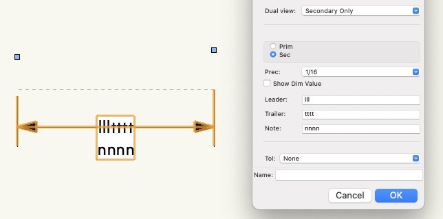
This is in VW2023. I've not had this issue before but last time I used a keynote legend was probably a couple of VW versions ago. The index numbers aren't aligned properly with the text descriptions. Most obvious with no. 9 here. Does anyone know what might be causing this?
-
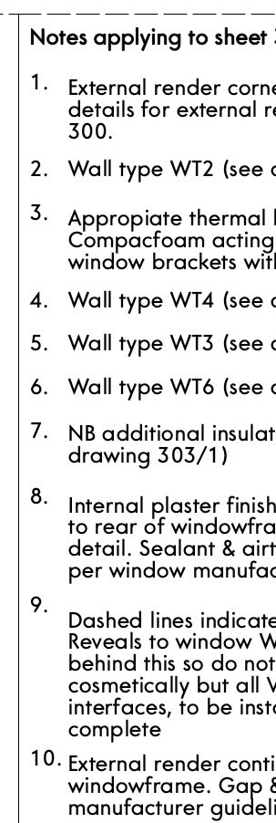
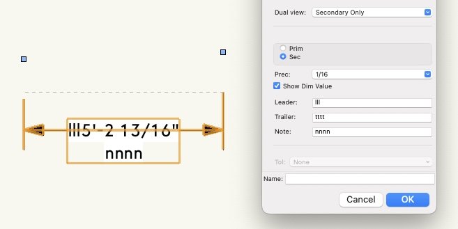
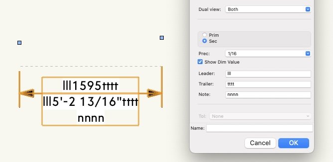
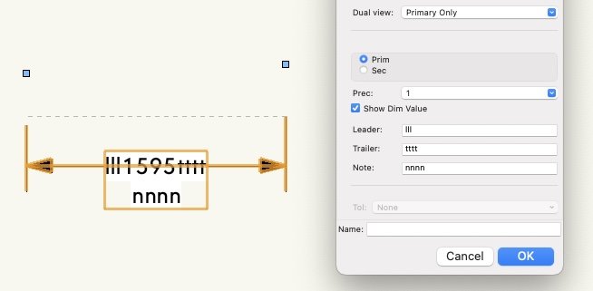
I've not used "dual view" dimensions before but I can reproduce what @skipper sees. Trailer text does not show up when dual view = secondary only, unless you untick "show dim value".
- 19 replies
-
- 2
-

-
- custom dimension
- dimension
- (and 1 more)
-
How do I Make a Curved Wavy Wall (Curved in Plan and Elevation)?
line-weight replied to Jack2022's topic in Site Design
If you want to be able to easily edit/adjust the object after you've created it, I would avoid using a loft (because if you want to change it, you have to start again. You can save the source curves on a hidden layer/class to make this a bit easier, but I find this a rather fiddly approach). I would first have a go using the methods @E|FA suggests above. -
Does anyone use a pen tablet for vectorworks?
line-weight replied to hongjun's topic in General Discussion
It's a Huion (now a few years old) that I have. As per my post above I don't use it as much as I thought I would. I'm not able to compare directly with a Wacom unfortunately. -
Section Viewports
line-weight replied to shorter's question in Wishlist - Feature and Content Requests
Ok, so then we have a vertical cut plane effectively rotated 90 degrees so that it is laying as a horizontal plane, right? What I don't get is how you would then meaningfully relate the 0,0 for this plane to a 0,0 in the 3d model. It's straightforward for a top/plan (or horizontal section) viewport to have its X and Y zero points superimposed on the model's X and Y zero points, because nothing has been rotated, and the Z values become irrelevant. It's different for a vertical section though. Its cut plane might intersect with the X axis, or the Y axis, or both. What lines up with what, or determines where it is placed? -
That's my experience too. Therefore I no longer waste my time doing it.
-
Did you go through the formal bug submit process, yourself?
-
Section Viewports
line-weight replied to shorter's question in Wishlist - Feature and Content Requests
I am still trying to understand the workflow/method. If you create a vertical section viewport on a design layer you get a kind of 3d object, right? Rather than a 2d thing, like you do on a sheet layer. And the cut plane, which is what you want to trace from, therefore exists on a vertical plane. So how do you trace from it in (or use it as an underlay for) 2d linework? Where is the 2d linework drawn? Or do you use "display flattened"? -
Section Viewports
line-weight replied to shorter's question in Wishlist - Feature and Content Requests
So is your method that you generate section viewports from the model, lay them out flat on a design layer, then have another design layer (only containing 2d linework) that you kind of trace them through to? And then that 2d stuff gets viewported to a sheet layer? I think I would try and use grid lines & elevation benchmarks as my checks that things had not moved. -
Line pen attributes custom and "by class"
line-weight replied to Cristiano Alves's topic in General Discussion
Like @Pat Stanford says, you don't have to commit to any particular "scale". Let's call it "zoom preview" instead (I think it shoud be renamed to something like that). You could start out with a "zoom preview" scale of 1:100 and at a later point change it to 1:50 or 1:10. And back again, as many times as you like - it won't have any effect* on the drawing geometry and it won't have any effect on what anything looks like in sheet layer viewports. You can just choose whatever's convenient for whatever you are working on at the time. In fact, the more you draw in 3d, the less relevant it becomes. These days I draw almost entirely in 3d so I am hardly ever drawing a 2d line directly (except in viewport annotations). Therefore things like previewing line thickness is not really a concern. I actually tend to have all my design layers set at a 1:1 "zoom preview" but this is to do with navigation in 3d. I use a 3dconnexion device and it means I have finer control over the motion. This is a bit of an obscure requirement though. I do have an issue when I want to edit things in a design layer in top/plan view, because then hatches become very dense, for example. *having said this, I'm not sure why you got the error message you posted above, about "parametric constraints" becoming invalid. You say it's when you changed the scale to 1:1000. Was that when you tried to change the scale/"zoom preview" of a single design layer? -
Section Viewports
line-weight replied to shorter's question in Wishlist - Feature and Content Requests
My details are extracted directly from the model, so usually they are sheet layer section viewports that directly display model geometry, with some additional info added in the annotation space. I'm aware this method may not work for others. I'm just curious how your approach works; I don't understand why a section viewport needs to be on a design layer and in a particular location. Isn't it the section-elevation line, the one that determines where the section is taken, that's the thing that needs to be in a specific location? -
Thanks for your reply. If it's a bug, then I think you should find someone within VW to register it.
-
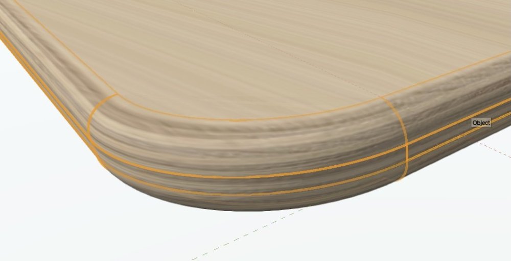
Agreed. In particular it would be good to have a way of texturing materials with some kind of directional grain in an intelligent "3D" way. Like you I'd be interested to know how other softwares deal with this.
-
"cylinder" map pretty much manages it although not with great image quality (have increased the radius of those fillet edges for clarity).
-
@Senthil Prabu these "self-intersections" in source polygons quite often cause things to fail in VW. It's quite easy to introduce them without realising, and it can be quite hard to find them. It would be good if - when this causes a failure - we could get an error message that tells us that this is the problem. Because in many cases, the operation just fails, or we get some kind of generic message, and this does not help troubleshooting.
-
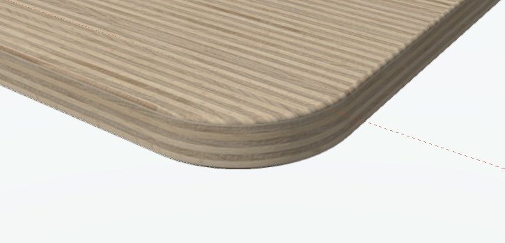
If I do no overrides, plane mapping, and then rotate 90 degrees I get this. The top face is wrong of course, but would not matter if hidden by a thin layer laminate as a separate object.
-
You could also choose to model it as per reality, with a plywood core and then a thin laminate layer on top. Then give each object the appropriate texture.
-
Line pen attributes custom and "by class"
line-weight replied to Cristiano Alves's topic in General Discussion
Ok, the main thing to understand is that when you change a design layer "scale" in vectorworks you aren't really changing the scale of anything, it's just changing how it is presented to you - how it is "previewed" if you like. This is confusing and I've long argued that the terminology should be changed, to stop confusing people. When you change the "scale" of a layer in VW nothing at all happens to the geometry itself. If you've decided that 1 drawing unit = 1mm then that doesn't change. If you import something externally you just need to make sure that the drawing units match. So, if in your file 1 drawing unit = 1mm then you make sure that you import geometry such that in the imported geometry, 1mm = 1 vectorworks drawing unit. Depending on where it's coming from you might need to rescale it during the import process to achieve this, but once it's in VW you don't need to change it again. You can set different "scales" for different design layers in VW. So if you have a 10mm x 10mm rectangle on one layer, with layer scale = 1:1 and you have a 10mm x 10mm rectangle on another layer with layer scale = 1:10, and you have both layers visible at the same time, one rectangle will appear 10x larger than the other. But it's not. Change both layers to the same scale and the two rectangles will be the same size. -
Section Viewports
line-weight replied to shorter's question in Wishlist - Feature and Content Requests
What do you use section viewports for, on design layers? What are they placed relative to, and why? -
Bend an object along a nurb curve
line-weight replied to Neves+Creative Inc.'s topic in General Discussion
I agree with everything that benson shaw says. I think that trying to measure on the drawing to predict where the ends of the bent sheet material will end up, when attached, is destined for failure. If I wanted joints to be in specific locations, I would choose those positions such that the predicted edges of a bent sheet oversail them a bit, and work on the assumption that the sheets will be trimmed back on site. The issues you touch upon, of faceted curves and accuracy of snapping to them, these are a bit of a problem in vectorworks in certain situations. What is and isn't a problem is a bit complicated. But I'd say that in general terms, as soon as you start doing complex curves especially things like NURBs curves in Vectorworks, then in practical terms expect to lose a bit of precision. If you are preparing drawings for some kind of high precision manufacture then VW may not really be the right tool. However... the reality of building construction is that nothing is actually that precise, and you can get away with "near enough". But it does need some careful thought in how you prepare the drawings, and some sensible allowance for tolerances. -
I know it's easy for me to be an armchair critic, but whatever the current system is for ensuring good UI design, it doesn't work. If someone like me, a lay person, can spot UI inconsistencies everywhere then VW are not allocating sufficient resources. There needs to be some kind of tyrannical pedant (or perhaps a team of them) who looks carefully at every aspect of anything that is introduced (well, and everything that's already there too). The thing that's been raised in this thread, this should not have slipped through the net. Of course if you give someone a button that says "flip" they are going to expect that pushing the button will make the gate flip. Because (correct me if I'm wrong) that's what happens everywhere else in VW: if you press a button then the thing the button does happens instantly. If there's a dropdown with options, or somewhere to type a numerical value, then we know that usually this means the changes will take effect when the dialogue closes. That's fine, because it's what we expect. You close the dialogue by pressing OK. When you press OK it closes the dialogue and commits the changes. Again, pressing the button is what makes something happen. @Tom W. above has already suggested a better way of doing this, with radio buttons. I'd suggest something like that too. But it shouldn't need users to point this out. This is a very basic issue of consistency and expected behaviour. This absolutely should have been picked up before release. I do recognise that there are certain things where the best way to do something is debatable, and you have to choose one way or the other and some users will disagree with the choice. But this example, it's not one of those. I don't see why anyone would want to have a button that doesn't do anything until later, which gives you no preview of what's going to happen later, and gives you no record of how many times you've pressed it. There are no possible advantages of this. It simply is bad UI design, and a professional software package shouldn't be getting released with stuff like this. Again, I don't want to come across as criticising the people who develop & code the tool. I'm criticising the system VW has (or doesn't have) in place for thoroughly checking things for UI issues. That checking needs to be done by someone who has not had any involvement in the development of the tool itself, so that they can come to it in the same way a user might come to it.
