


line-weight
-
Posts
3,755 -
Joined
-
Last visited
Content Type
Profiles
Forums
Events
Articles
Marionette
Store
Everything posted by line-weight
-

Stories v. Non-Stories (Residential Design)
line-weight replied to Ryan Russell's topic in Architecture
The thing is, I'm pretty sure all these confusing aspects of storey levels have been raised before, several versions of VW ago, but no moves seem to have been made to address them and make the whole thing more user friendly. I find this really frustrating where something could be made a bit less confusing simply by changing the terminology at least as a starting point. That doesn't need any change to the hard coding, it just needs a change to what things are called (or how they are presented) in the UI. -
I have a feeling this has been discussed before but can't find the thread. For some reason, I am always finding that I draw something, in a certain class, and it gets drawn with attributes that are not "by class". In these cases, I don't remember telling VW to do this. I make sure I have all objects deselected, and go to the attributes palette, and choose "make all attributes by class", thinking that this ought to mean that anything I draw from now on, will have all attributes by class, but somehow it doesn't always happen and I'm back in the state where I draw something and it has attributes that are not by class. Like I say, I think I remember this discussion being had before. I'm sure technically it's caused by some kind of user error, but whatever that user error is, it happens all the time. It would be good to have some sort of button to press, to stop it happening.
-
Stories v. Non-Stories (Residential Design)
line-weight replied to Ryan Russell's topic in Architecture
Storeys is one of the areas where the terminology that the VW designers have chosen makes everything ultra-confusing. I have to go back and read my own notes each time I deal with storeys. What I want there to be is an absolutely clear distinction between: - Storeys - Storey level types (a level type, for example FFL) that might occur in any storey - Storey level type instances (an individual instance of a level type, for example 2nd floor FFL) I want to know exactly what I am editing or creating at any point, and the current UI and terminology makes this very confusing. For example, "default storey levels" are really default storey level types. I think. When I am editing a "storey level" I am actually editing a storey level instance. I think. I think you're right, there's not a way to edit the elevation of all storey levels of a particular type, together, to be a set value relative to the story. "Default storey levels" are just a set of storey level names that VW gives you. Part of my routine is to delete them all, when I am setting up a new file. I don't generally work on buildings with large numbers repeated storeys so I kind of dodge all this by just having one storey for the whole building, and then having a bunch of storey levels within it, so I might have several FFLs within that . Reading all this is probably going to stress the OP @Ryan Russellout. Sorry @Ryan Russell. -
Stories v. Non-Stories (Residential Design)
line-weight replied to Ryan Russell's topic in Architecture
Probably best to post a file and explain specifically what you want to do and why. The tops and bottoms of walls can be bound to story levels, plus or minus an offset. Or they can be unbound. The usefulness of stories depends on quite a few things including how many floors the building has and how likely you are to want to change things like floor-floor heights in the future. There is seldom a clear "best practice" with Vectorworks... this is one of its strengths and one of its weaknesses and I can understand must be immensely frustrating when you are new to it. -
Vectorworks 2023 Service Pack 4 Available for Download
line-weight commented on JuanP's article in Tech Bulletins
Seeing the 3D dragger added to (some) operations is very welcome. I hope we'll see it available for more commonplace actions too - like simple repositioning and rotating of objects using the selection tool. -
VW2023 is slicing my models in front of my eyes (shaded view)
line-weight replied to line-weight's question in Troubleshooting
Happy to report that this does indeed seem to be fixed in SP4. Thanks @Dave Donley. -
Might work in some scenarios... but what if there's a sloping pitched roof immediately above that furniture - unless the threshold "slice edge" can be not shown, you'll see that staggered drawn where it cuts the sloping roof.
-
Can I show an "X" in sectioned timber structural members?
line-weight replied to line-weight's question in Troubleshooting
Thanks. Have added to the other thread. Looks like the answer to my question is basically "no" at least not in a useful way. -
I have tried adding what I want to "front (and back) cut" of an indvidual structural member's 2D components - but without any success - nothing appears in the section viewport. However.... I don't think I'm going to spend time working out what I'm doing wrong, because as @Tom W. says above, it doesn't seem like this can be added as part of a style, so it's not very useful anyway. I don't see why the section symbol can't just automatically be the same as the symbol you use for the "shape" when you make the structural member style.
-
Can I show an "X" in sectioned timber structural members?
line-weight posted a question in Troubleshooting
Generally timber members, when cut in section, are drawn with an 'X' like the left hand version above. I've got in the habit of adding all these Xs to my sections in annotation space, because I tend to just draw timer beams as extrudes, so VW would have no way of knowing I want that X when sectioned. However, I'm now trying to make use of "structural members" which I was hoping would allow VW to give me those Xs automatically in my section viewports, but it's not, and I can't find the setting that enables it ... is there one? (Next question is, is there some way to set up custom behaviour for sectioned timer so that I could show something like the rihjt-hand version above?)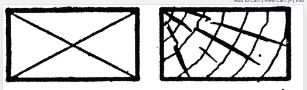
-
Yes, that's exactly the problem I'm describing in my post above yours @luiza_finger. For me the most logical render is that you see the (horizontal) elevation lines of the edges of the table until they hit the threshold - then they simply stop. But you don't see any (vertical) lines where the table edges are "cut" by the threashold.
-
While we wait for styles to come, I wish they could just make some of this stuff less confusing, not by changing the way anything works but using better wording in the UI. Just for example, instead of "Symbol Selection: [Current Settings]" (what on earth does this mean to anyone who doesn't already understand how this works?) and "Save as Symbol" (save what as symbol?) something like: "Import settings from: [choose symbol]" (makes it clear that a bunch of railing/fence settings can be imported from a symbol, and that the dropdown thing lets you choose one) and "Save current settings as Symbol" (reinforces that you are saving a bunch of settings, not an actual object, as a symbol) Doing this kind of thing wouldn't need any fundamental re-coding. But these confusing interfaces persist year after year, despite multiple people having difficulty with them. Really brings to mind the video I posted in this thread. All of Vectorworks' design decision makers should be made to watch that video. Or just employ the guy who made it.
-
The way this tool works is really confusing. See this thread (particularly about 7 posts down)
-
Structural Member usability improvements
line-weight replied to LarryO's question in Wishlist - Feature and Content Requests
...and I'm also having loads of problems trying to use "custom" member types where I choose a custom 2d symbol for the shape. Editing the 2d symbol doesn't seem to change the structural members that use it, unless you switch to another symbol and then back again. And it refuses to let me select certain symbols. I can't reliably replicate this in a clean file, and haven't currently got time to pin down something replicable. For now I'm considering the custom shapes unusable. -
Structural Member usability improvements
line-weight replied to LarryO's question in Wishlist - Feature and Content Requests
Another bug for you @Matt Panzer. Combining a longways "start" offset with a negative Z offset for the axis creates this: File attached. SMoffset.vwx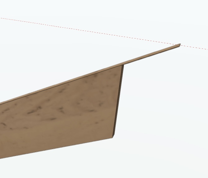
-
Wall Joins - T+L join creates unexpected geometry
line-weight replied to StefanoT's question in Troubleshooting
The way VW tries to join walls, with a kind of diagonal mitre, to me is just fundamentally wrong - hardly any kind of wall is built like that in real life. -
Wall Joins - T+L join creates unexpected geometry
line-weight replied to StefanoT's question in Troubleshooting
I think it's just the last one that's from another package (I'm going to guess Bricscad) The first 4 VW ones each have something that hasn't worked as you'd want it, for instance internal or external finishes continuing through junctions. -
Structural Member usability improvements
line-weight replied to LarryO's question in Wishlist - Feature and Content Requests
Thanks for the response.- 16 replies
-
- 1
-

-
- structural
- steel
- (and 2 more)
-
Non horizontal/vertical reference planes
line-weight replied to line-weight's question in Wishlist - Feature and Content Requests
A bit more on my single-storey approach in a thread here That was before I started using EBs though. The EB functionality is kind what has swung it for me now, so that I feel it's worth having that storey level setup (the usefulness of which I felt was otherwise a bit limited). -
Wall Joins - T+L join creates unexpected geometry
line-weight replied to StefanoT's question in Troubleshooting
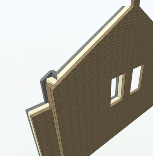
@zoomer's examples perfectly illustrate the many common situations where multicomponent wall joins just don't really work properly. There are quite a lot of scenarios where I have to abandon the wall tool for large portions of buildings and just build it all from generic solids. Here's a bit of a building I happen to be working on just now. No T joins but some changes in level, and a pitched gable. Haven't even started on foundation and floor connections yet. Not worth fighting will wall tool settings for this kind of thing.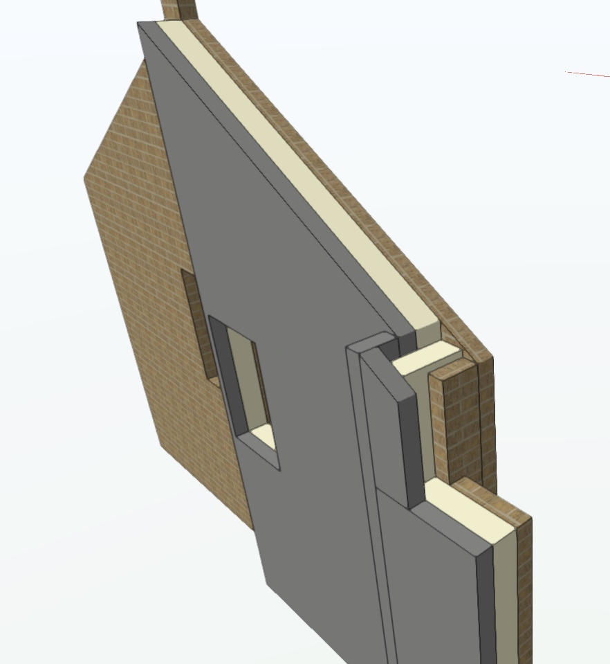
-
Non horizontal/vertical reference planes
line-weight replied to line-weight's question in Wishlist - Feature and Content Requests
I use stories (sort of) yes. Actually I just create one storey and put everything in it. That allows me to create storey levels and then my elevation benchmarks are tied to those. In each elevation or section viewport I can then choose which benchmarks to display. They appear in the annotations space but reliably at the right levels. -
Structural Member usability improvements
line-weight replied to LarryO's question in Wishlist - Feature and Content Requests
I've just revisited this in 2023 SP3 and I don't think anything has changed from my comments above, based on testing in SP2. @Matt Panzer are you able to give us any hints on whether we will see any further improvements soon - and also, I think there are some bugs that need to be addressed. Downloading the file I attached to the post further up should make it easy to replicate some of the things you can see happening in my screen recording. -
I've just been reminded, while working on a current drawing, of another, related issue: You can choose to entirely exclude certain "beyond the cut plane" elements from the background of a section, by using the "finite" option for "Extents Beyond Cut Plane" and specifying a distance. So for example you can say you don't want to see anything that's more than 2m beyond the cut plane. There's a problem with the way this is implemented, though, because VW draws it as if you've sliced the model along that 2m line. It means that in certain situations, you see a line representing the cut edge of sliced elements. But this is hardly ever what you'd want to see; you don't want this cut edge to be shown. Unless there's some option I'm missing, there's not currently any way to get around this other than judicious choice of depth of extent, such that no such lines appear but this often forces the depth to be something other than what you really want.
-
Non horizontal/vertical reference planes
line-weight posted a question in Wishlist - Feature and Content Requests
One of the biggest recent improvements in VW is that we now have a fairly good reference grid system, thanks to the Grid Line tool (effectively creating vertical reference planes) and the elevation benchmark tool (effectively creating horizontal reference planes). The ability to set these up, know that they will stay in the right place and be independent of changes to the geometry of the model, and have them appear in the right place in viewports makes working in 3d feel a lot more secure and manageable, and allows various double-checking procedures to make sure things are where they are supposed to be. I think it would be useful to have the facility to have reference planes that were neither horizontal or vertical. I'd be interested to see if anyone else would find this useful. Or maybe it is really a fringe request. An example of when I might use it: Sometimes I do works to existing buildings parts of which effectively get rebuilt, but need to be reinstated where they were. That might include pitched roofs. I might need to ensure that the outer surface of a pitched roof ends up where it was before even though the underlying construction has changed entirely. In this case, when preparing setting out drawings, the plane of the pre-existing roof surface is what various things need to be set out relative to. In this case it would be very useful to embed that pre-existing plane in the model as a reference. Just like I might do with an elevation benchmark set to an existing finished floor level, or a gridline set to the face of an existing wall, I could show an indication of this same plane in "existing" and "as proposed" viewports and double check that when I place things like new rafters, I have actually go them in the right place relative to what's important. I think they could also be useful in keeping a handle on the geometry of things like new-build roofs too. Obviously there would be a few things to think about, like whether they could appear on any section that intersected them, or only in views parallel with the plane and so on. But in principle they'd be very similar to gridlines and elevation benchmarks. -
Better PDF optimisation
line-weight replied to Christiaan's question in Wishlist - Feature and Content Requests
yes! Also, at the same time as sorting out file sizes can we sort out the problem of colours changing during PDF exports.
