


rowbear97
-
Posts
207 -
Joined
-
Last visited
Content Type
Profiles
Forums
Events
Articles
Marionette
Store
Everything posted by rowbear97
-
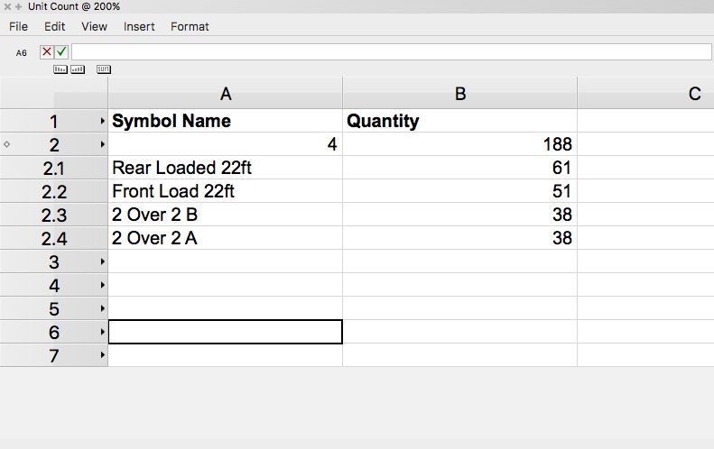
I'm clearly out of my league here! I've looked around and done a little experimentation yet I am no where closer to finding a solution. I'm working on a project where I want to inventory symbols. In this worksheet I have created criteria that counts all the symbols and sums up the symbols with the same name giving me a count that is accurate. Here is the tricky part. I want to take the inventory of different symbols by name and add them together as well as multiply one particular symbol by two to give me a final total number of units. What am I missing or is this a functionality that doesn't exist?
-
Jay, Thanks for this. I'm familiar with this rectangle however my client wants a square just like the hexagon with the quantity over the plant ID just like the attached image. Thanks again for your time and support.

-
I'm working on a project as a contractor and my client wants the plant bubbles to be rectangles, not like the one provided, but more like a square the same size as the hexagon but a square instead. Anyone have any ideas on making a custom Tag Bubble? Any assistance will be greatly appreciated. sample-finished planting plan.pdf
-

Dashed Line Endings - Rounded/Square Option
rowbear97 replied to ericjhberg's question in Wishlist - Feature and Content Requests
I had the same thought and suggested that they make line types for each pipe size if needed. -
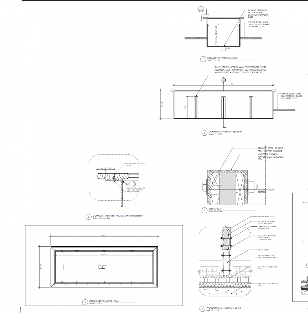
Realize that this inquiry might have been directed to Stephen or Eric; however I do have a project where we modeled and detailed everything in 3D. The planter box plan, section and enlarged detail of the cap are in 3D.
-
Stephen these look fantastic! Are your axons and illustrations of the signs from VW as well? I'm so jealous you get to do all this site work with my practice mostly urban rooftops I miss those days. :-(
-
Ben, If you go to Tools > Options > Line Thickness you can modify the line thicknesses to your liking. Much like AutoCAD where you can modify the CTB you can change these settings to your preferences. I have done this as I think the line weights are too thin as well. As for hatches I have modified or imported a ton from AutoCAD as well. One helpful hint here is that AutoCAD hatches will be in all sorts of crazy scales depending on the original setup as either one unit is one foot or inch, so be careful. And when all else fails try using tiles. What this all comes down to, and I know how it is as you are under pressure to deliver, you must keep updating your template and have discipline to use the template to start your drawings each time. Good luck and let me know if I can be of any assistance.
-
Data Visualization - Auto-Range
rowbear97 replied to Tom Klaber's question in Wishlist - Feature and Content Requests
I way out of my element here but is there a possibility that Marionette might give you a solution(s) to these planning issues? -
Nice looking drawings Eric!
-
Vw Marketing Videos Don't Show Actual Vw Workflow
rowbear97 replied to rDesign's topic in General Discussion
I would have to agree with gester. The rvt import is way too cumbersome and I have already told my clients, who are Landscape Architects, not to get rvt files as they are useless. At least with the .ifc import you can control visibilities and the architects who send us the files can send us only the skin. -
Ben, How have things been. I'm not sure that I have "Site Plans" to share but I will look and check with my clients if they care if I post to a forum. Perhaps I'm too accustom to or don't have the same high bar as you do but what exactly do you find "terrible" about this drawing? Perhaps if I had more detail about what it is in this drawing that is terrible. Is it line weights, text masks, hatches? Like I said I will see what I can release and post in kind or even send to you via drop box. It would appear you are using the keynote feature of the annotations. This is pretty advanced. Hope things are going well otherwise.
-
Thanks so much for the timely response! I'll give it a try.
-
I have a sloppy file from Microstation to AutoCAD to Vectorworks and in this file there are topographic contours that come in slightly off the Z elevation they should be. Is anyone aware of a Marionette script that I could use that would round either up or down to the next whole integer? Any assistance on this would be greatly appreciated.
-
Great video.
-
Alan, Thanks so much for the assistance. Perhaps I can return the assistance some day.
-
Thanks Alan and Marissa on your contributions to this effort. I've incorporated the two different items and have a marionette that works exactly as one would expect. Now my challenge is that the values that are being added to the worksheet are no longer dimensions, giving me feet and inches I'm getting a text. This wouldn't be an issue if in the worksheet I could change the cell from text to a number but for some reason I can't do that. The idea in the worksheet is that the user will get the volume, usually given in terms of yards for us landscape industry folks but also required to give cu.ft. for our structural engineer friends to be able to calculate loads. Additionally we would like to use the worksheet as a material schedule showing the dimensions of the planters length, width, and height. Again thanks in advance and I look forward to seeing what comes next. You can download the file here. Oh and as a side note. This one marionette object is already over 26 megs. Is there a pending solution for the bloated size?
-
I've been working on this with some help from others on this forum and wanted to post my progress and seek some help on solving a couple of nagging issues. One when I change the height of the box it moves up from the ground plane. Now when I was in Chicago just yesterday Sarah suggested using the node "Set PRefID To Ground". I tried this and continue to get the same result. The other thing I'm trying to do is have the attached records report the entered values so I can build a work sheet that will allow us to calculate volume for each planter even as you change the sizes. Lastly, again perhaps I missed something during the one on one with Sarah but I want this to be a symbol. When I take the marionette object and convert it to a symbol it shows up as one in the resource browser but when I drop that symbol into the drawing it shows as a marionette object. Please see the this file and let me know if anyone has any ideas on how to address these items.
-
Thecaddshop - Marionette Nodes Vol.1
rowbear97 replied to ahedley's topic in 3rd Party Services, Products and Events
I would have to agree with Gilbert about the ability to encrypt or lock out once a custom wrapper or marionette object has been created. While your points are good ones I feel like there is a business opportunity here that we could leverage expanded understanding of marionette to our clients. That's my two cents worth. -
Haven't experienced this issue and have not heard from any of my clients that they experience such a thing. Would you want to share a file and someone, including but not limited to myself and we could try and see if we get the same result? You mention changing the 2D graphic to 0,0 this should be your default on the symbol definition to avoid just such an issue. But you have been using these same symbols previously? This is a shot in the dark but could it be page based versus world based for the symbols? Hope this helps.
-
Alan, This is fantastic. Its the damnedest thing that you can look and tinker and the moment you have someone with a different perspective look at something...bam! Thanks so much. I suppose it would be simple enough to invert the process such that when you change the depth of the box it moves the top edge of the box not the bottom up. Again thanks so much! What is that font, mapped it to lame Arial now can't find the name? Could you send that to me? Robert
-
I started with the idea of taking Jonathan Pickup's cabinet marionette and simplifying it to make a planter only to realize that, while this almost works it is fashioned on the thinking of cabinetry and slabs butted together rather than a cast or molded item made of concrete or similar. What I would like to do is create an object that is formed from the inputs of the user defining the dimensions of the planter (Width, Depth, Height, Wall thickness, Finish) and the resulting marionette object would appear, just as Jonathan's example as an AutoHybrid object. After that is solved I would like to make this object have attached records allowing for use in a worksheet. It would be nice if we could create the object by either extruding two rectangles and subtracting the smaller from the larger thereby making a whole with the wall thickness factored in or draw a double line polygon based on the dimensions and then extrude that shape to the height desired. I could not find nodes that would do any of these things. Is this something that I can add to the wish list or did I simply miss them? The image is of the script as currently configured and a start above of trying to consider an alternate path. Thanks in advance.
-
Multidiscipline office with VW and ACAD stations... advice please :)
rowbear97 replied to TDWrks's question in Troubleshooting
I have worked with numerous outside consultants using Autocad and have developed CAD standards for Autocad and VW Landmark. I did want to address one item directly that you wished there was a way to add a prefix to imports. There is within the single DWG import dialogue. Additionally if you are using the Autocad files as background only have you considered importing them as a reference file. The resulting workflow could be something like, reference Autocad file with stationary name e.g. job#_mech.dwg and each time an update comes along simply overwrite this file. Place a copy of the CTB in the folder with the reference file that way the line weights will map to the desired setting. Best of luck. -
Can you share an screen shot of the landscape area or even better the actual file. So we can have a look?
-
Ben, Haven't seen any response from your inquiry and thought I could follow up and see what I can do for you. Would you be willing to share the file and I can give it a crack here? You have my email, reach out to me if you still need assistance.
-
I would love to but the native files are over the size restrictions here. You can see these are legacy files from ESRI.

