Search the Community
Showing results for tags 'dtm'.
Found 14 results
-
 I am experiencing an issue with Site Models where the underlying existing site data is being altered to meet the grade limit boundaries, when the Site Model picks up modifiers (The Grade Limit is set to affect Proposed only). The Site Model is on its own design layer, the Site Modifiers are on a separate layer, and all the modifiers are set to affect the proposed site only. The grade limit is also on the same layer as the Site Model. Can anyone provide assistance to resolve this problem? Is it a known bug? Tagging the experts here 😄 @Tamsin Slatter @bgoff @Pat Stanford Existing Site Model Problem with Grade Limits.mp4
 -

Saved View, Site Model status
Benson Shaw posted a question in Wishlist - Feature and Content Requests
I tried to make 2 saved views, one showing DTM exist, another showing DTM as proposed. I don't think this is possible, because update needed. But would be nice time saver, for instance comparing effects of site modifiers to existing. -B -
Hi All, On my digital terrain model, I have draped areas from my 2D plan and want to extrude these surfaces so they follow the landform. So far I have only been able to send the 2D polygon to the surface and then extrude it from there. Is there anyway of showing a 3D shape that has a constant height that matches the contours? Any help would be much appreciated.
-
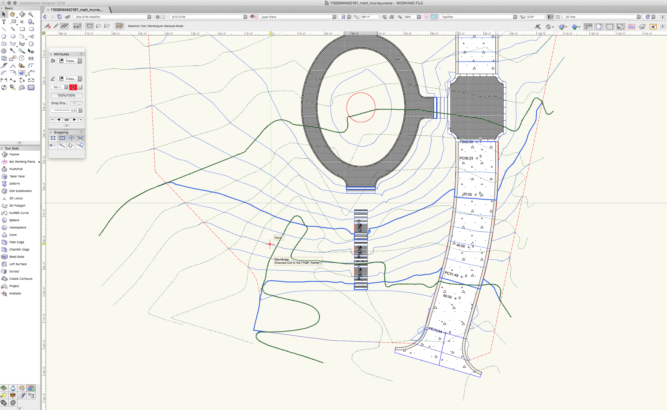
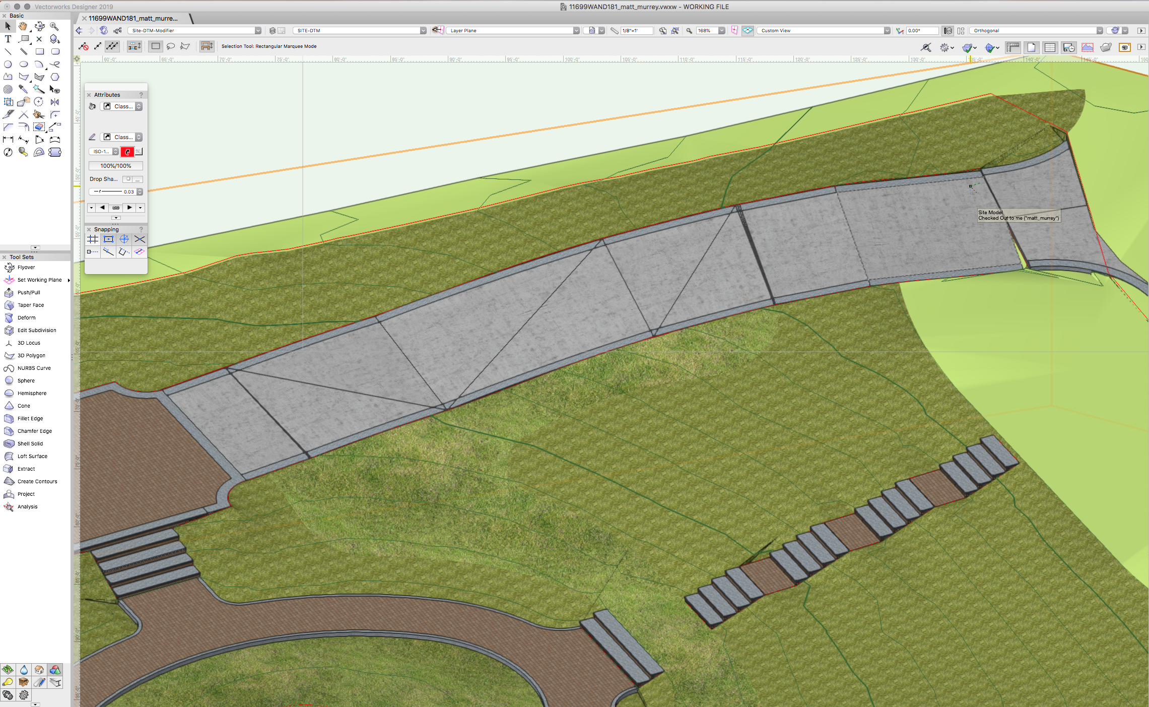
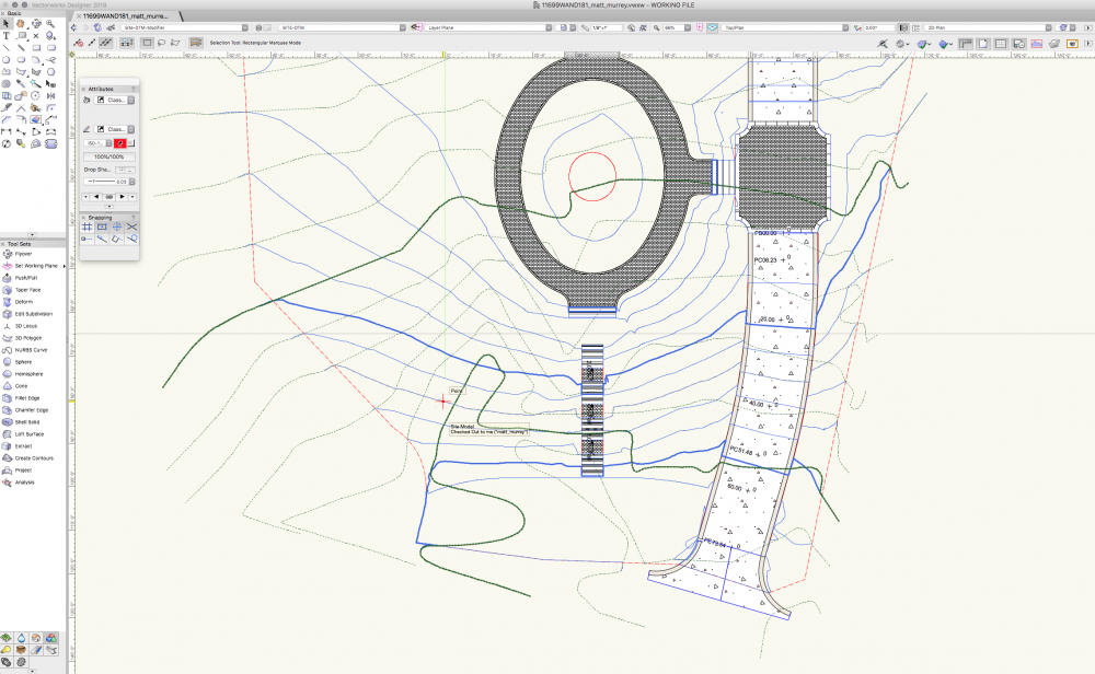
Hello. I have a road poly going down a slope. There is a pad modifier at the bottom of the road and the grade limit is set to the property boundary. I added a nurbs curve to the top edge of the road for finished grade at the road edge. 3D view shows to be accurate (top of paving = to adjacent grade). The contour lines however are not following the top of paving, instead they are following the 'cut' below the road on the DTM. While this is accurate for the cut, it is not accurate in terms of a site plan. Is there any workaround for this? See attached screenshot.

-
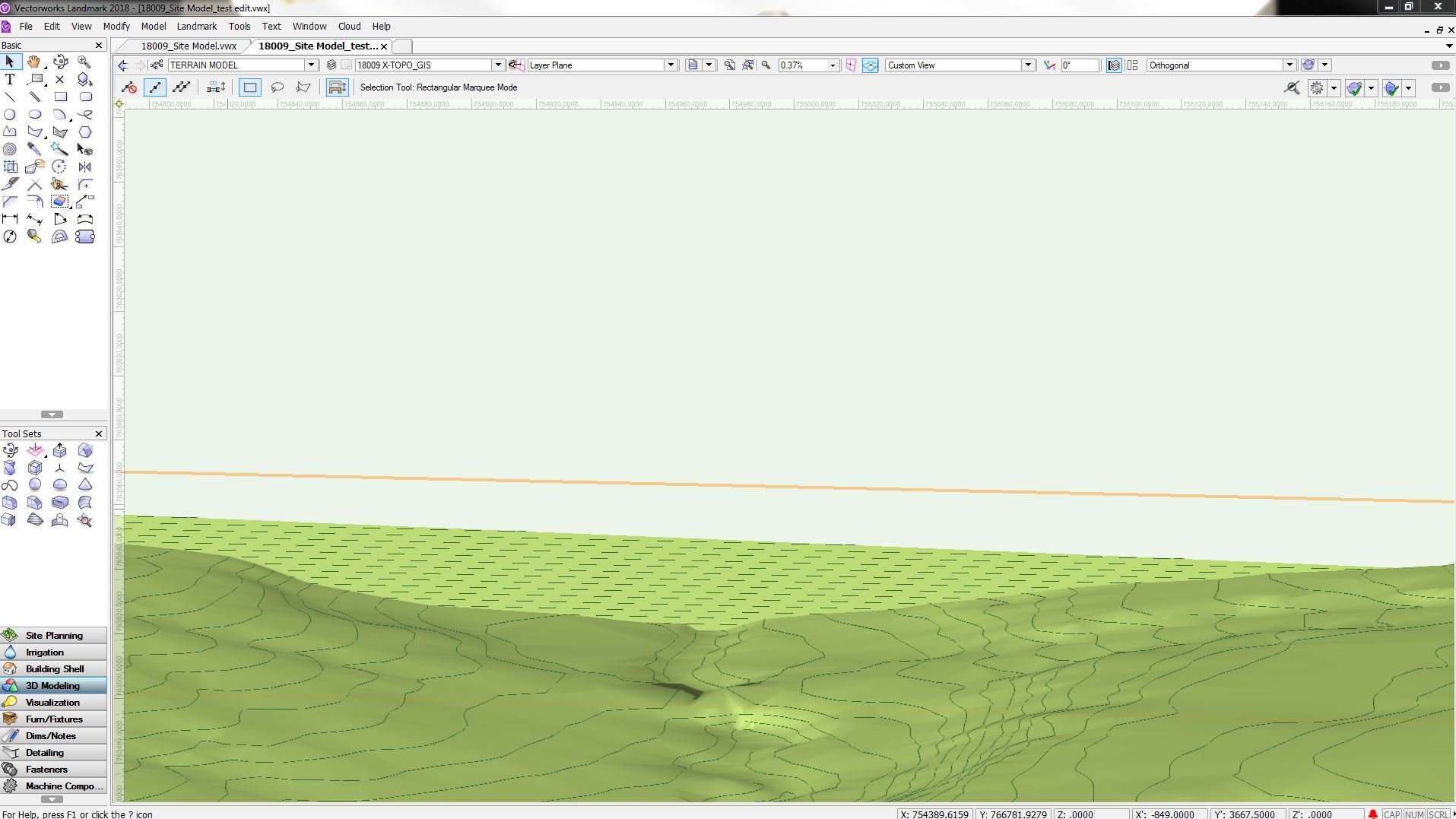
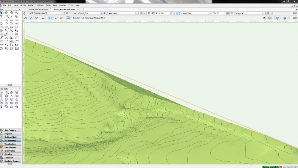
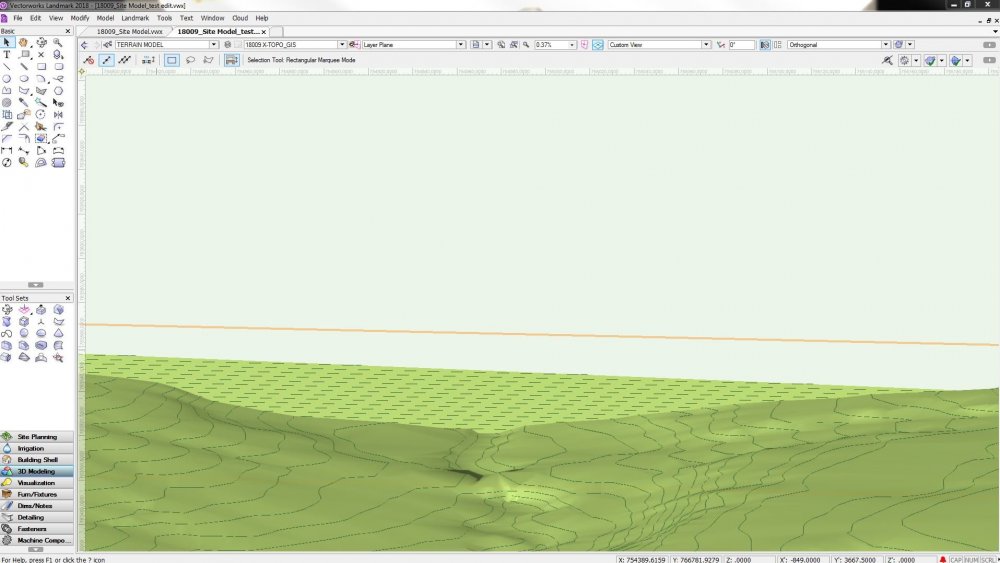
I've successfully imported polyline contours from AutoCAD and created a Digital Terrain Model. However, where the contours run off the boundary of my project, Vectorworks is closing them with the nearest contour of the same elevation. This creates a vertical "wall" of terrain/contours at the edge of my site that I don't want. (see photo). I assume it does this because Vectorworks places 3D Loci on top of the polylines and uses the loci, not the polylines, to generate the model. Is there some way to avoid this, or some way to correct it? I tried to "Edit Site Model" and then slice out the connecting portion of the contour, but it seems to revert when I exit the Site Model editor. What am I missing?
-
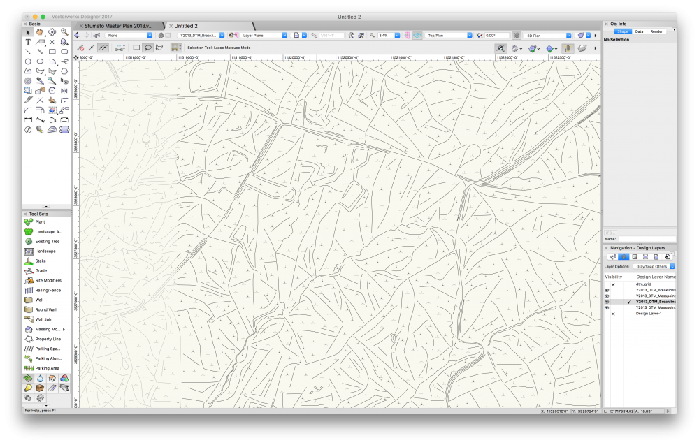
I have four DWGs from Albemarle County's (VA) extensive GIS system. Two different grid blocks, mass points and breaklines for each. I can bring them into a file and they show at elevation when the view is rotated. I can get them all onto the same design layer, but how does one use these together in creating a site model? I could generate something with just masspoints but I'm betting the breaklines are there for a reason. In trying a test, it didn't seem to comprehend the data by default. I also have the 4' topos and a site survey of a much smaller area with stakes for elevation points that were measured by the survey crew. They didn't do a lot of the paddocks which is our focus in this project, so trying to get better than 4' data before I just go shoot it myself. Screenshot of area in question attached before I merged them to one design layer (hence the left being grayed out) VW Designer 2017 if it matters.
-
I love VW 2018 with one BIG exception. I can no longer right click on a site model and view or edit the source data! I called tech support and they said that feature went away with the 2018 release. I may very well go back to 2017 for this feature. Ask anyone who regularly imports survey data and generates topo maps and they will all tell you that it is very important to be able to go in and delete or edit bad points. Why oh why would Vectorworks remove a very basic important feature like this? Hopefully tech support was wrong and someone can tell me how to edit survey points after creation of a site model. Thank you, Glenn Troyer
-
Is it mandatory to drape "2D" Geometry of Modifiers on the DTM first ? It has been a while since I created my DTM but see that all Modifiers were draped on the DTM surface (which I think I wouldn't have done if working without ?) Especially I mean : a) Texture Beds b) Retaining Edges around (flat) Modifier Patches As I see the Modifiers still working ALTHOUGH some of them meanwhile lost parts of their Z-Position against the DTM (Maybe from doing modifications like moving or adding points that tend to jump in Z)
-
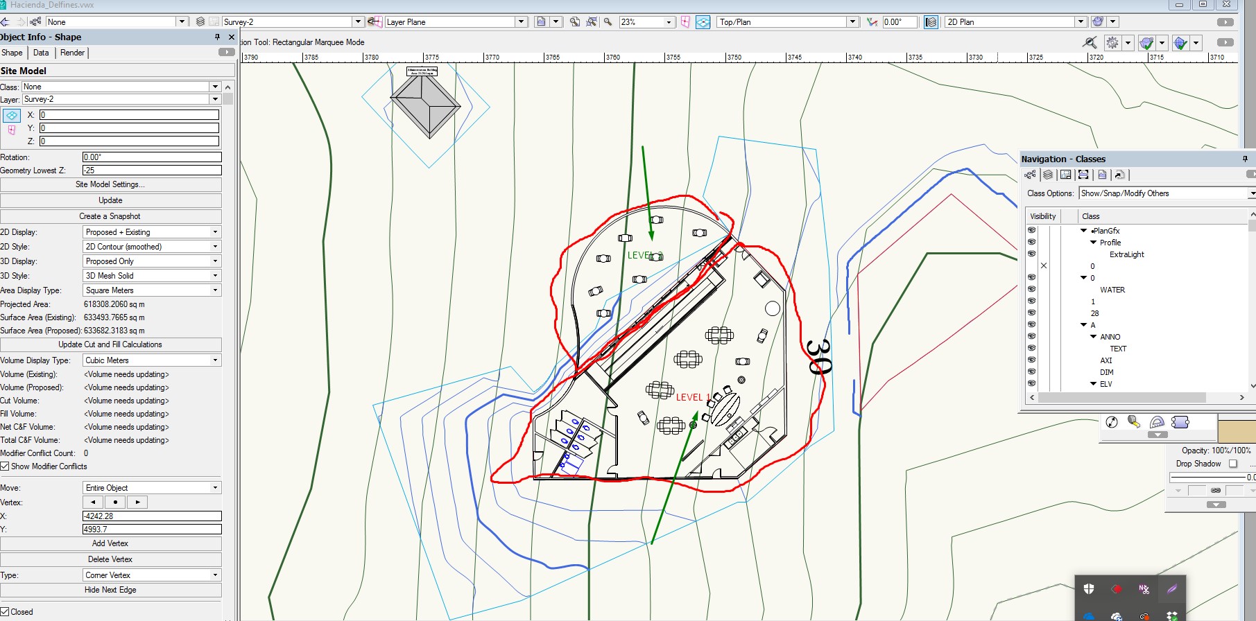
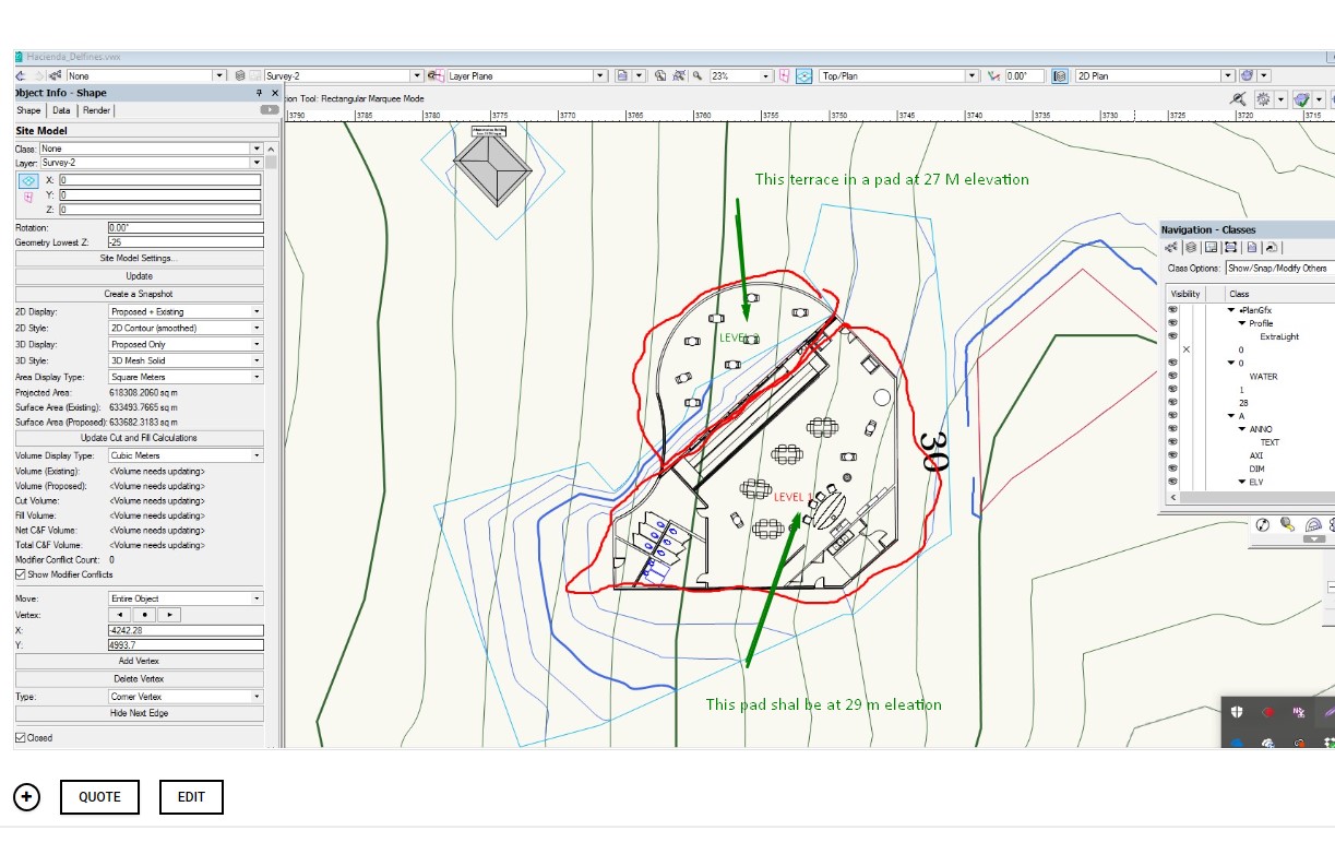
I am working with getting refine skills in Site Modeling. I have a small building resting over a steep hill . I designed one floor building with a terrace at one level and the remaining area steps up into another pad elevation. I have trouble setting the Site Modifier for Pad with retaining wall and normal pad. The problem that I face is that the pad are joined together alone the line that separated both sections of the building returns an error. What technique I need to apply? IS there a better technique to tackle this situation. I sea a lot videos but they don t really take into account Pad modifiers that are aligned one next to the other touching together. Here is a link to the VW drawing... https://www.dropbox.com/s/ro2ke5nzk1dqqh0/Hacienda_Delfines.vwx?dl=0
-
This is a simple and consider a common scenario but not able to get a solution. I created a Digital site model using 3D Polygons that where converted to 3D loci. I am not happy at all with the resulting Contour site model. I realized that I needed to add additional 34D polygons data in order to enhance the resolution of the site mode. But I am not able to return to the original 3D polygon not the 3D loci data. I double click the edge of the contour site model, but all I get is the Site model parameter windows. I do not want to change the model using modifiers. I just want to recreate the site model.
-
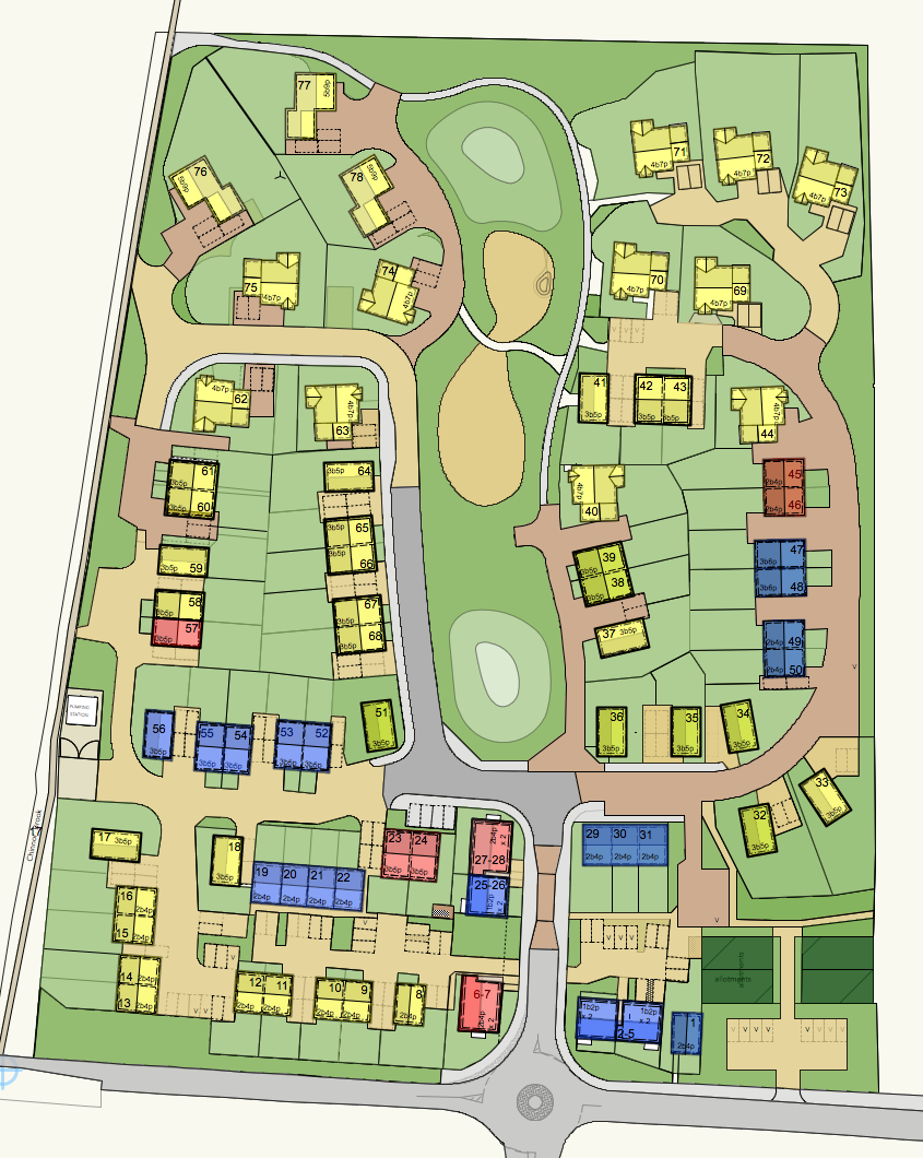
Does any have advice for producing an all singing dancing DTM for the attached site plan? It's slopes about 9 m in elevation across the site. I've used DTMs on occasion but nothing substantial. This is the first DTM that I've done which is reasonably large and complex and which we will rely on heavily for documentation. 1. I started by laying out roads using the Roadway tool but I soon ran into the limitations of this tool. Unless roads intersect nicely at rights angles etc it seems pretty useless. Is there a more flexible way? Model my own modifiers and roads? 2. I've also found in the past that it's easier to use the 3D Polygon tool to form site modifiers—placing them on the modifier Class—than it is to use the Site Modifiers tool. I find it easier to create the shapes I need. However there doesn't seem to be any way to use 3D Polygons and also produce a retaining edge. Am I missing something? 3. How best to group modifiers? Should I create large pads forming the mains steps in the site (which will include building sites, gardens, roads, etc.) or should I start off straight away modelling the roads and separate pads for gardens, building sites etc.?
-
Hi All, I’m a year out landscape architect. I have a 3D mesh digital terrain model created in vectorworks from OS contour data. What I would like to do is drape an image over that landform, for example the 1:25,000 OS map or a google earth image. I have tried to add the image as a texture as well as draping the bitmap over the landform, neither of which has worked. Is there something I’m missing here. Are there any image file types that I should be using? Any help would be much appreciated. Thanks.
-
Hi All, This is my first post. I am a landscape designer and currently have a job where we have been able to use a standard survey to create a Digital Terrain Model (DTM). We have been also able to gather a survey of where the sandstone is below the soil level on the site. My question is, is there a way to map subsoil profiles such as a bedrock layer so that I can do a rough estimate on how much soil vs sandstone will need to be excavated. This is critical to this job as the client is adamant about the budget and need to assist the contractor in quoting for excavation. It will also be useful to plan for any stone that we want to be exposed. Hope you guys can help.