GGC
-
Posts
22 -
Joined
-
Last visited
Recent Profile Visitors
857 profile views


-
I appreciate the info. Thank you
-
I use a workaround to represent a single object image to print somewhat legibly by increasing the lineweight. In a single object image representation in a worksheet condition the workaround is feasible, however in conditions where each worksheet entry is a unique object then the workaround to duplicate all the existing objects in the layer/drawing to increase the lineweight to around 30mils is prone to errors. Could anybody share any hints how to increase the object image resolution in a Worksheet as a result of the =image function?
-
I have been attempting to further revise the script to work inside groupts, symbols, and viewport annotations. Though I used the GetParent to obtain a handle of the container (group, symbol, or viewport) for GetLayer to use for GetLScale the factor that I need to use for page units the script will find the CallOut PIO however not the the handle for the layer thus GetLScale=0, thus obviously the text margin set will become 0 (zero) for CallOut PIOs in groups, symbols, or viewports. I have researched in the forums and noticed that for some reason VS needs a handle for each specific container condition other than design layers, that is a quite a puzzle. Could anybody share a thought if there is the possibility to obtain a handle for each CallOut PIO regardless of the container or not to use for GetLscale(GetLayer(GetParent(CalloutPIOhandle). Procedure SomeDialogValue; Var H1:Handle; LyrScale, MrgnCall, MrgnValue :Real; Default, Request, MrgnValueStrng : String; Procedure GetValues; Begin Request := 'CallOut PIO Page Unit Text Margin'; Default:= '0.03125'; MrgnCall := DistDialog(request,default); If NOT DidCancel Then BEGIN End; End; Procedure Callback(H1 :Handle); Begin MrgnCall := MrgnCall; LyrScale := GetLScale(GetParent(H1)); MrgnValue:= LyrScale*MrgnCall; MrgnValueStrng := Concat(MrgnValue); SetRField(H1,'Callout','Margin',MrgnValueStrng); ResetObject(H1); SetDSelect(H1); End; Begin If NOT DidCancel Then GetValues; If NOT DidCancel Then ForEachObject(Callback, ((INSYMBOL & INOBJECT & INVIEWPORT & (PON='Callout') & (('Callout'.'Bubble Style'='None')|('Callout'.'Bubble Style'='Vertical Accent Bar'))))); End; Run(SomeDialogValue);
-
Thank you Julian, your revision works. I appreciate you taking the time to revise my newbie attempt.
-
I have been attempting to complete a simple VS dialog input for the CallOut PIO text margin based on Page Units. So far, i was successful to repeat the dialog for each of the selected PIO. I have researched extensively how to pass the dialog value input (once inputed) for each PIO selected, however I could find the appropriate answer at least for my VS newbie lexicon. I am attempting to pass the Dialog Value inputed once to the Procedure to repeat for each selected PIO. Could anybody share a bit of VS wisdom about how to pass the Dialog Value inputed once to repeat ForEachObject? Initial VS that obviously requests a dialog input for each selected PIO: -------------------------------------------------------------------------------------------------------------------- Procedure SomeCalloutMrgnDialog; Var H1:Handle; B1:Boolean; MrgnCall, MrgnValue,LyrScale:Real; MrgnValueStrng,default,request:String; Procedure SetObj_Value(H1:Handle); Begin request:='CallOut PIO Page Unit Margin'; default:='0.0625'; MrgnCall:=DistDialog(request,default); H1:=FSActLayer; LyrScale:=GetLScale(ActLayer); MrgnValue:=LyrScale*MrgnCall; MrgnValueStrng:=Concat(MrgnValue); SetRField(H1,'Callout','Margin',MrgnValueStrng); ResetObject(H1); SetDSelect(H1); End; Begin ForEachObject(SetObj_Value,(((VSEL=TRUE) & (PON='Callout')))); DoMenuTextByName('Previous Selection',0); End; Run(SomeCalloutMrgnDialog); -------------------------------------------------------------------------------------------------------------------- After my extensive research an attempted VS to repeat the Dialog Value for each object. Though, after I input the value once for more than one selected PIO nothing happens. Procedure SomeCalloutMrgnDialog; Var H1:Handle; B1:Boolean; MrgnCall, MrgnValue,LyrScale:Real; MrgnValueStrng,default,request:String; Begin request:='CallOut PIO Page Unit Margin'; default:='0.0625'; MrgnCall:=DistDialog(request,default); LyrScale:=GetLScale(ActLayer); MrgnValue:=LyrScale*MrgnCall; MrgnValueStrng:=Concat(MrgnValue); End; Procedure SetObj_Value(H1:Handle); Var MrgnValueStrng: String; Begin SetRField(H1,'Callout','Margin',MrgnValueStrng); ResetObject(H1); SetDSelect(H1); End; Procedure Last_Step_Proc; Begin ForEachObject(SetObj_Value,(((VSEL=TRUE) & (PON='Callout')))); DoMenuTextByName('Previous Selection',0); End; Run(SomeCalloutMrgnDialog);
-
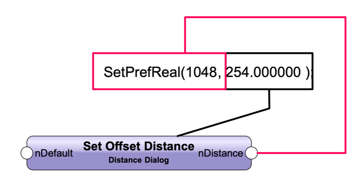
In an attempt to set the Smart Cursor Snap to Edge Offset Distance by dialog value input, I could not find a Marionette Output for such a Preference output. (see attached screen capture) Is there an output option in Marionette for any preference value output? Any hints are appreciated.

-
As far as I know the PIO default settings set in the plug in manager are valid in new drawings, until any parameter is changed, or inclusive create similar command picks up whatever parameters the PIO settings has and sets the drawing PIO default settings (not the PIO global defaults). To edit all the CL PIOs in the drawing, the Custom Modification tool (under the Tools menu commands) would select all the type CL PIOs (under criteria) in the entire drawing, then all the CL PIOs parameters in the drawing can be revised via the Custom Modification OIP all at once. To set the drawing PIO default settings, just use the create similar object context menu command on the desired CL PIO which would result in the new PIO default settings in the drawing. HTH
-
Dublicate Array command Presets
GGC replied to markdd's question in Wishlist - Feature and Content Requests
Since this topic is up, I would add to keep the array objects similar to constrained chain mode "grouped" (not as the typ. group obj.) as a PIO like with the array parameters available in the OIP which could be edited as needed without the need to delete all the array objects and redo the array for any reason revisions. Whenever such an array PIO entity would not be needed, a convert to group (or ungroup) command would simply turn the array PIO entity into the arrayed original objects similar to ungrouping the constrained chain dimensions. -
If anybody is interested in a workaround about the possibility to switch to another viewport annotations with minimal mouse actions below is at least one such possibility using two utility apps. (Keyboard Maestro and Better Touch Tool) In my version I use a mouse tap to call the BTT coincidence "context menu like" to select the command, click to select the command (shortcut to activate the Keyboard Maestro sequence), lastly click the next target viewport. As a note, "edit annotations" (or any context menu command) in the context menu can be assigned a keyboard shortcut in the system preferences. The keyboard shortcut will Only work when the context menu is active. Simulating a Ctrl + click in keyboard maestro then the edit annotations command shortcut will trigger the edit VP annotations. The setup sounds more complicated then it is to set it up. . If anybody is interested I can post a screenshot of the sequence I use.
-
VW 2020 - Worksheets Crashing Program?? Anybody??
GGC replied to uglycat's topic in General Discussion
I have had a similar experience with worksheets. What worked for my workaround was to import the worksheets that crashed the app in a new blank file.... then open the worksheet make an insignificant change, then save the blank file, then import back the worksheet into the initial drawing file where it failed. -
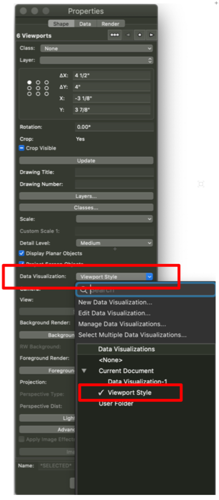
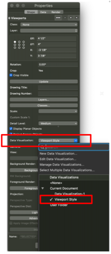
Until Viewport Styles will become a reality here are the steps with which such a workflow is possible for edit once for X Sheets For class or layer visibility only select all the target viewports in the organization menu → edit to turn on or off the target class or layer For graphic attributes and visibility 1st define the needed graphic attributes in the Data Visualization dialog Next Select all the target viewports in the organization menu → edit → turn on the target class or layer and select the Data Visualization setting previously defined (see OIP screen capture) Note that the Data Visualization tool is only available when a design layer is active Update: The Data Visualization setting will remain set when switching to saved view design layer(s) environment → need to switch to Data Visualization setting to none, or find the preference or VS script to add to each saved view to switch the Data Visualization setting to none. To expand on the Data Visualization viewport option either as a wish or bug: As long as Data Visualization is an option for specific Viewports it does not make sense for the Data Visualization setting for specific viewports to remain visible in the design layer(s) environment.
-
Command to zoom out to "floaters"
GGC replied to Paul Vanderwal's question in Wishlist - Feature and Content Requests
To delete objects outside any page boundary the "Purge" command has three options (see attached screen capture.)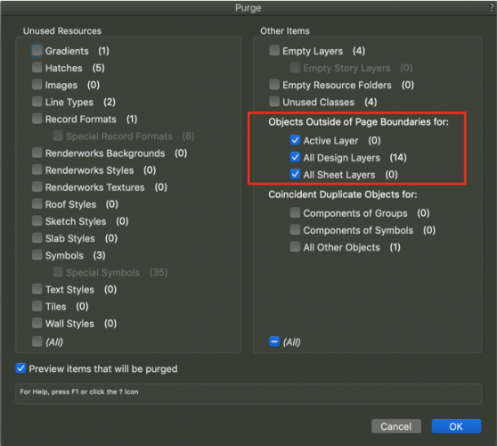
-
Disclaimer: Any of my comments below are in a sense my subjective proposal for the mentioned improvements to be taken in consideration only, Not a Demand. Any reader who for whatever reason believes that the tone of any my comments imply a connotation of Demand can refer to this disclaimer. To begin with from my experience there is significant distinction between the glamorous process of 3D modeling, or 2D design development drawings, or any hybrid combination of 3D modeling and 2D drawings, and the production drawings annotation process. During the production drawing annotation process, I can say with certainty from my own experience, and of other users I met that the spirits are high about the precise annotations necessary Not only for the plan check/permit requirements, however additionally for the builder to interpret the drawings accurately excluding as much as possible any RFI requests during the construction process. Even though many projects are similar holistically, every single project is Unique, therefore each project's annotations are unique to the project as mentioned before not only for plan check/permit requirements, however in addition for the building process, therefore during this process of high spirits a streamlined annotations workflow would be highly valuable. As a side note, there are a variety of 3rd party hardware, and software available that facilitate heads up menus for any programmed menu item, or keyboard shortcuts time savers and especially stress. Worksheet improvements: • Keyboard shortcuts: All menu commands to have the ability to be assigned keyboard shortcuts that work at all times -Currently, I can assign keyboard shortcuts in the mac os system preferences, however the keyboard shortcuts only work sporadically. • Format cells options - Alignment tab: Having all the alignment options as graphic Icons visible would help to easily click the needed option without the need to choose from a pulldown menu, where the user could easily miss the needed option, or sometimes forget the need to assign the proper alignment. - Patterns tab: Similar to the Alignment tab to have all the pattern options displayed as graphic icons to easily click the needed fill, rather than choose from a drop down menu when many times either the item below, or above is accidentally selected. - Border tab: currently, there is a graphic representation of the border options, however having all the options available as graphic icons similar to the typical worksheet software would be a time saver. • Or inclusive (excluding redundancies), add a toolbar with icons below the menu commands with all the typical menu commands (e.g. text alignment, summarize, sort, font, fill color, border options etc.) • Collapse/Expand Database Row - Currently, I have check list worksheets for various pios, or objects with records with 3 database rows--Selected, Visible, and All Having the ability to collapse/expand any of the database row rows would help • Freeze row(s), and Column(s) - As mentioned previously by other users this option would be an additional time saver. Walls Dimensioning: - Add a 2d locus or similar graphic representation at the center end of each wall so that dimensioning from center to center of of each wall would not require the typical need to double check sometimes to verify if the dimension snapped to the center of the wall. Such an option could have a toggle option in the tool bar along side the "Auto Join Wall" option. - In a previous post I mentioned the option for walls to represent their respective starts and ends while in top/plan view. If such a option would become available, then snapping dimensions to these respective graphic representations would eliminate the need for any additional graphic option. Templates: As much as I can set up a template, during any project the actual template improves while working with specific conditions. I find it a waste of time to copy the improved settings from the an actual project to a template. I could delete all the objects in the actual working file with the improved settings, however and especially with each newer version the file is prone to become corrupt. Therefore, the ability to import all or any Not only Design Layers, Sheet Layers and Classes, however in addition, Saved views, which will inadvertently import any design layers and classes with their default settings Stories etc. Or inclusive, preferably a "Create Template File Command" from a Current Working File where all the possible settings (including units, dimension standards, title blocks, viewports, etc.) can be imported would be a great time saver.
-
Callout text justification to leader line
GGC replied to Gadget's question in Wishlist - Feature and Content Requests
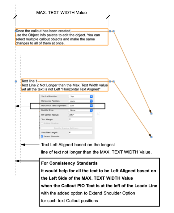
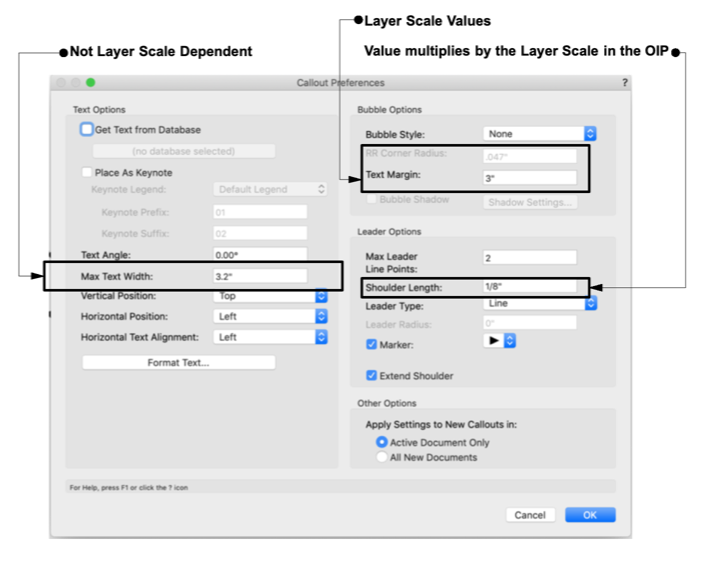
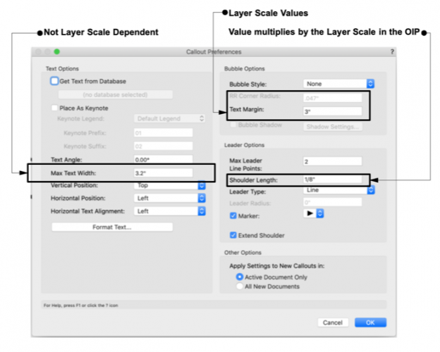
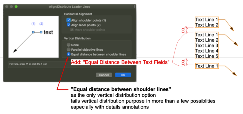
I will add another what I consider needed consistency--All the Field Value dimension settings NOT to be Layer Scale Dependent. The Text Options Section dimensions are NOT based on the layer scale--the "Max Text Width" value --a 2.5" max. width will still be 2.5" max. width regardless of the layer scale. The Bubble Options dimensions are based on the Layer Scale (i.e. RR Corner Radius, and Text Margin) Leader Options dimension are based on the layer scale (i.e. Shoulder Length) --(see screen capture reference) It would be a great time saver to have all the callout settings values NOT based on the layer scale in the Callout PIO Settings dialog, and the same values to display the same dimensions in the OIP. Also, if not mentioned thus far a "Save Settings" option would be an additional time saver in the Callout PIO settings dialog. ----------------------------------------------------------------------------------------------------------------------------------------------------------------------------------------------------------------------------------------------------- What I could not find a work around, is Left Text Alignment when the leader is at the right of the CallOut PIO (see the attached screen capture reference.) An additional note for the Callout PIO Vertical Distribution: "Equal distance between shoulder lines" as the only vertical distribution option fails vertical distribution purpose in more than a few possibilities...especially with details annotations. (see attached screen capture for more info)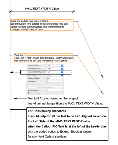
-
List the Callout PIO Layer Scale in a Worksheet Column
GGC replied to GGC's topic in General Discussion
I managed to save the script to run in any file per your referenced post. Thank you Pat.