Gadzooks
-
Posts
509 -
Joined
-
Last visited
Content Type
Profiles
Forums
Events
Articles
Marionette
Store
Everything posted by Gadzooks
-
Kevin, I've not had any problems with this as a solution for creating 3D elements, especially for planes. But thanks - good to know your own experience. My feeling is your suggestion seems overly complicated for the OP's situation, but I'm certainly not as used to NURBS as you are. In the circumstances I think @LarryOcould just as easily provide 1mm or minimum alternative fraction of an inch and still 'do the job' as required.
-
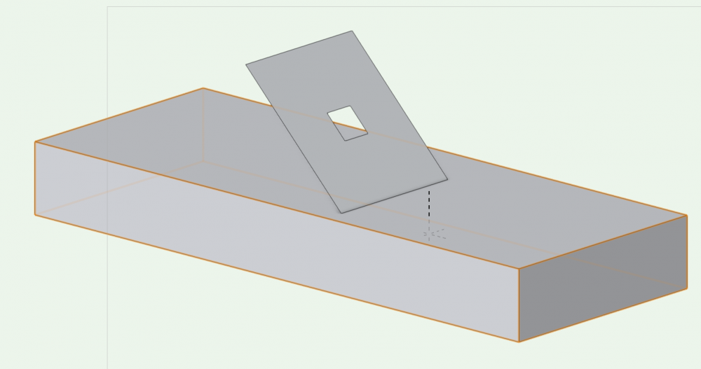
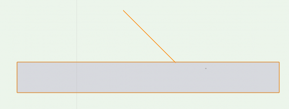
(If I understand correctly) Create a rectangle, place a smaller 'cutting' rectangle in position, Modify>Clip Surface, you now have your hole, Extrude to 'zero' ... Your plane with hole can now be placed in the model with zero thickness (when viewed from side) and can be tilted and rotated to suit. (with a base to explain) Iso side (highlighted) careful - you'll lose sight of it if not highlighted!!
-
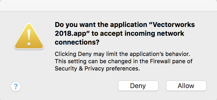
Hi - anybody else getting this every time on startup since SP2? Yes - I have set the firewall in preferences and I've even omitted VW2018 and re entered just in case a fix was to show the Mac the SP2 version. Still shows on startup - is this a 'feature' of SP2? Edit - to be clear, Ive set the firewall to Allow

-
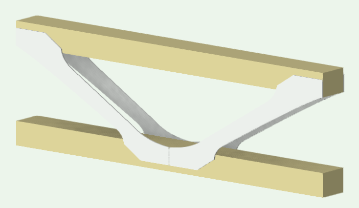
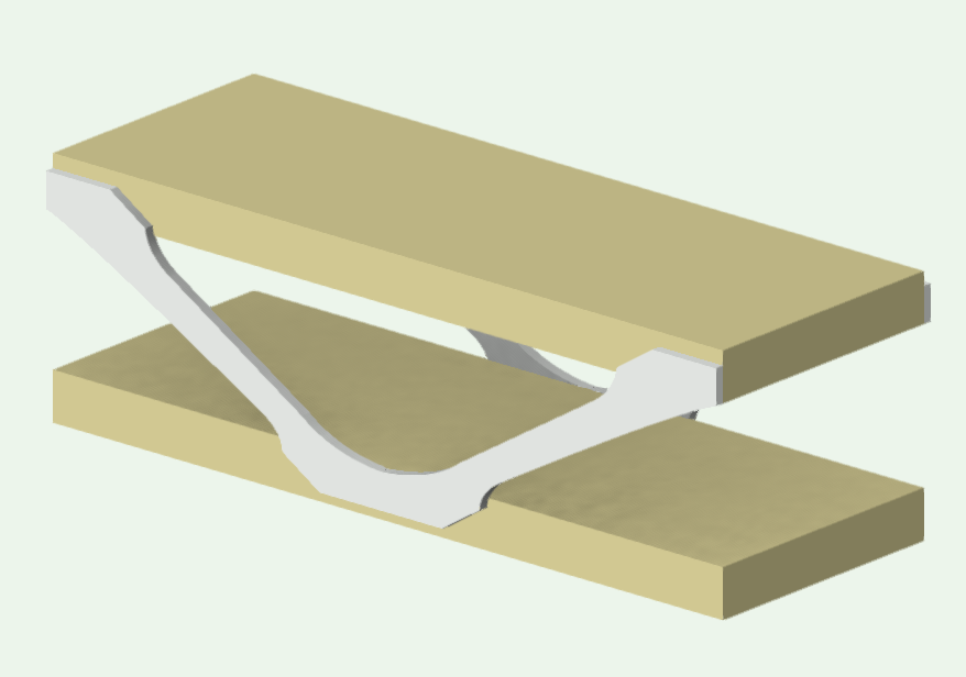
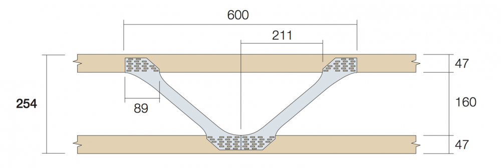
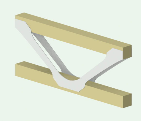
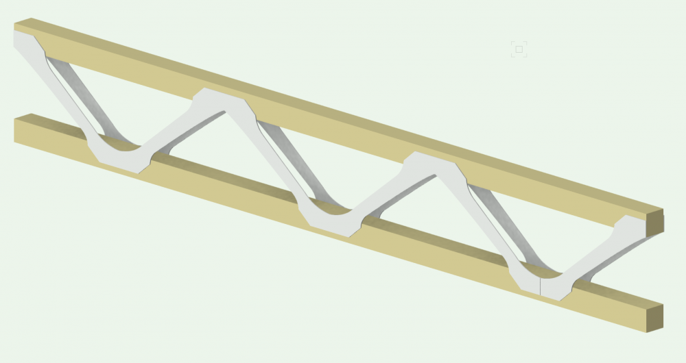
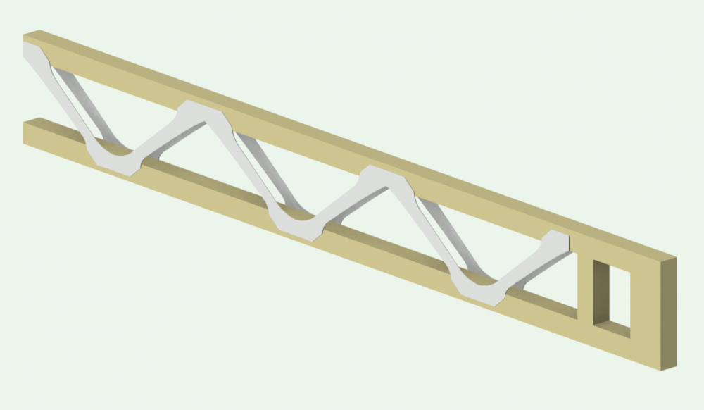
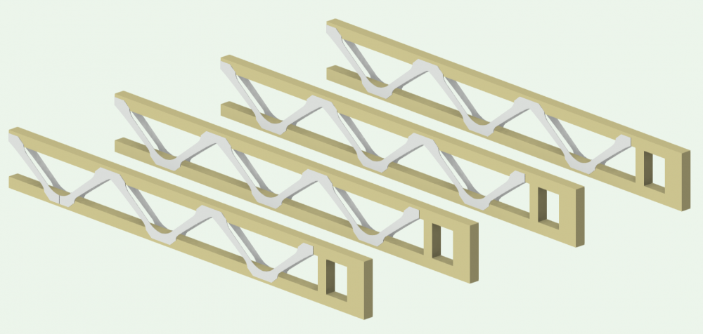
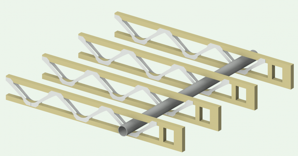
Thanks @Christiaanyou gave me a reason to think this through. I've wanted to have this and from time to time have fudged it. So this time I've looked at it a bit more seriously. I think - someone will correct me maybe - that the structural member or framing tools suffer (suppose drawback is a better phrase) from the way VW creates its arrays from symbols (even if they are 'bespoke'). The only symbols it can use are 2D 'outlines' and they are extruded and set out at the c/cs set in the OPI. Where you (and I) want to provide a little more refined (graphically) solution. First off, I recommend that the ply web type of joists are a good way of getting what you want using a 'standard' manufactured product and still being able to set some of the other options and flexibility available within the OPI including the production of the automatic takeoff etc... The key being that you can create a series of custom symbols from the manufacturer's range - all in outline. There's a reasonable vid on this...https://www.youtube.com/watch?v=BNoPJIrJOm0 I think there's no other route than to look at symbols and duplication for what we need. You'll have to do your own take-off unless you add data and provide a linked worksheet. Prob not worth doing as the manufacturers produce all this. As far as the symbol route is concerned I've taken the view that the modular approach looks best. We are only after representation of the joists - not total accuracy. At the design stage we cannot know where the final imposed loads/spans will affect the design and layout that the manufacturer 'spits-out' of their design software. Obviously as professionals we can set out a provisional layout from knowledge and can even go back in later to replace positional joists with accurate ones from the manufacturer's design output. 600 mm seems a good modular approach - most of the Wolf system (there are others!!) has this in typical fashion. Create a symbol to suit - bearing in mind it should be possible to 'squeeze' the height and width (to achieve the correct range they manufacture) and still maintain the top and bottom chords with metal web appearance. I chose to create the 254 depth so that later squeezing and stretching is easier as its from a 'mid range' point. Squeezed to the 195 doesn't really alter it too much - as the piece maintains the required 600mm 'module' and can even be used to create the 222 wide variation satisfactorily Then build your span - duplicate along line or which ever preferred way.. Ends can be treated to a block symbol to tidy the final dimension, much the same as the product would come from the factory. Then you have your fixed span to duplicate at the c/cs for the floor area and can even indicate services if required. Obviously doesn't have the 'extras' that are built into floor creation within VW, but a reasonable solution that will provide indicative sections/detailing and provide some help in MEP planning. Doesn't take long to draw up the small amount of symbol variations that make a layout quick to achieve. They can also be used for walling systems etc. - the world's your lobster (sorry non UK readers!) Hope this might help - or would be pleased to see other options on this theme. @JimWI can't edit this image out now its there. Have you been tinkering again


-
Nice one @Matt PanzerI tip my hat to you sir. Its all good with this learning. Everyone 's a winner.
-
Can I suggest you change your signature then. Both @Wes Gardner and myself were guided to provide you with an answer based on your use of '2014 SP4' stated in your sig. As for 2018, I can't replicate your problem. In fact I find clip cube is one of the more reliable VW features. Others might be be able to replicate.
-
Enough to have that from you. HTH
-

For Sale Vectorworks 2018
Gadzooks replied to Curtis's topic in Buying and Selling Vectorworks Licenses
Interesting that VW guys haven't stepped in and asked about your experience/lack of fit (to your particular requirements) or maybe not? What are we missing out? -
Google search found http://learn.archoncad.com/2015/11/26537/vectorworks-tip-337-creating-a-plan-viewport-from-a-clip-cube/ you'll see Jonathan's note at that time towards the bottom of the page.
-
Thanks @JimW
-
HTH - I'm learning too! You could use the link below this thread Support > Bug Submit. But I think what's asked for is a bit of a 'faff' considering the detail a lot of threads have gone through before we raise it with VW boffins. It would be easier to just use a thread reference, but I'm not aware the system exists.
-
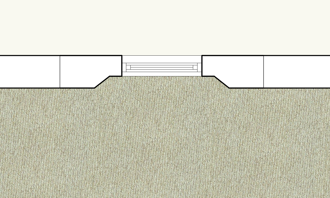
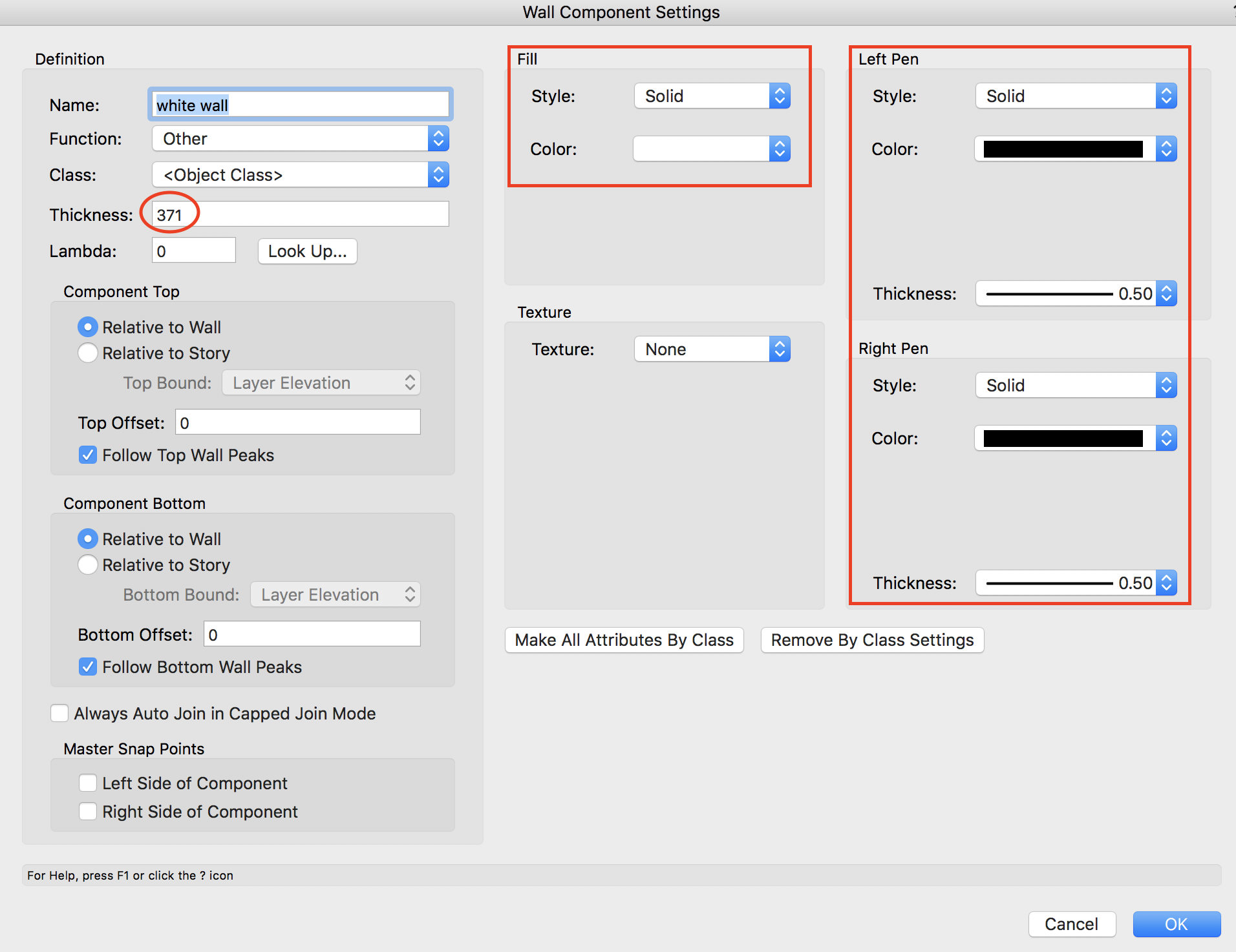
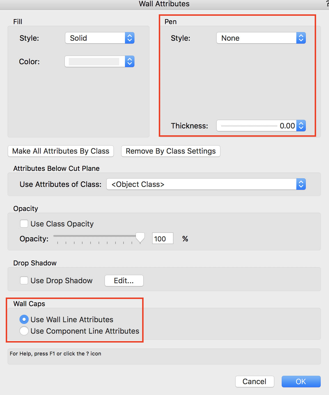
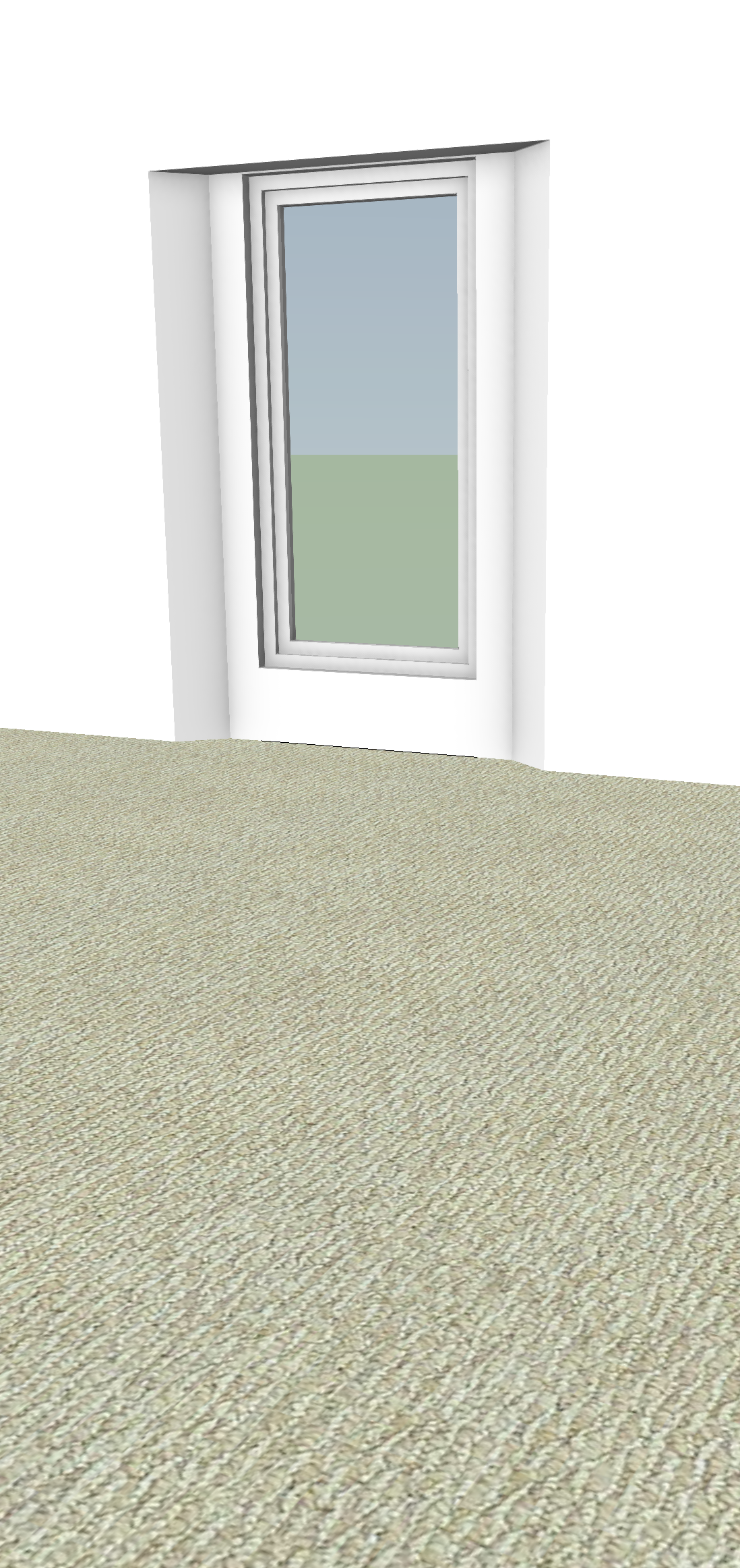
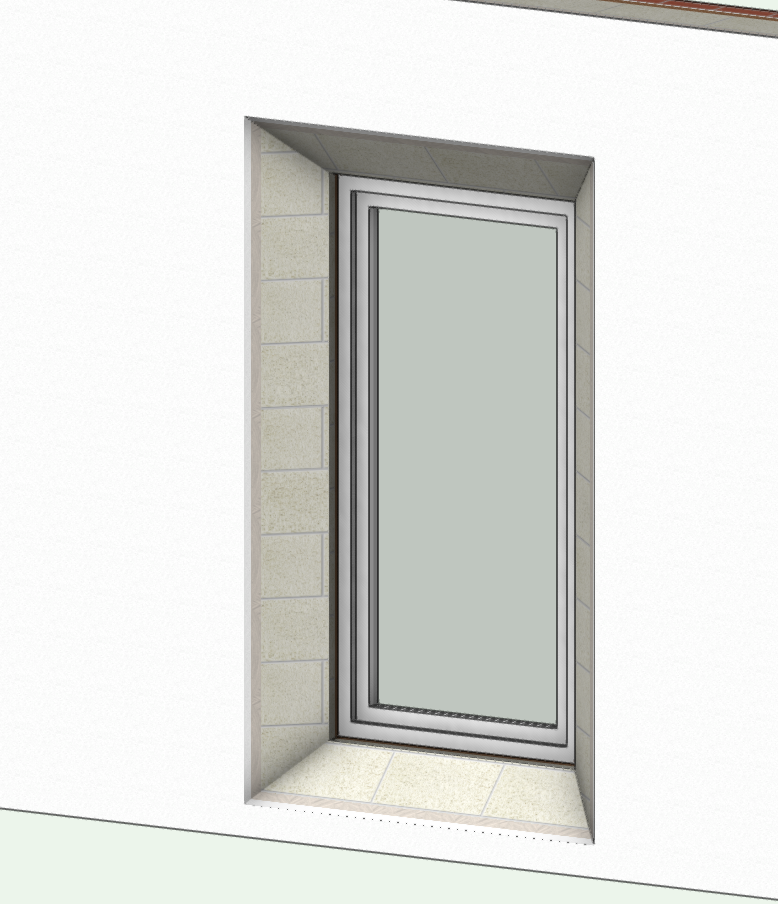
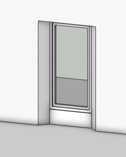
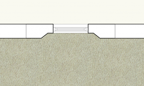
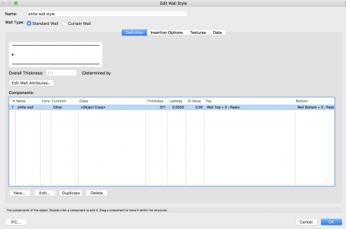
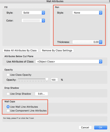
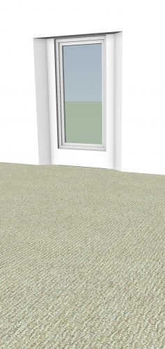
Thanks Christiaan - I appreciate that. (Blimey - better come up with something half decent ) Sorry @nikihoopsI may have left you hanging a little there, as I assumed from your OP that you wanted to prepare a 3D client presentation. You're quite right, the solution I suggested is far better in 3D. And, as you've found, 2D is irritating - to say the least - with the way VW wants to 'cap' everything. Your screen shot highlights not only the caps attributed to the window (obviously not normally seen in 'normal window/wall situations), but also the extra lines from the wall recess operation (which you can't really do much about in terms of adjustment of the solid used to punch the recess). As you've already discussed, the quick work-around is a liberal dose of polygons to mask the offending lines. If you choose to do that, you might as well make something 'useful' and create a floor covering for the room. Attach an image to it and leave it as a 2D only object (which will remain in place in your 3D visuals) . I've added carpet.. The fact that I see you've chosen to present the wall in a neutral white helps an alternative solution, as we can easily get rid of the cap lines another way. The wall I've used comprises just the one component..create yours as you wish... Set the component's attributes when you create it.. Just create the component as you wish the wall to be - white fill and reasonably heavy black left&right pens are chosen here to match yours. BTW - The thickness at 371 is just random (from an earlier wall) - set your own. Once the component has 'outstanding' features, you can turn off the wall from showing... Change the wall to basically 'nothing' and set the caps to use use those wall settings.. Obviously. there are a few ways of doing this (using white for the pen?) but I think as shown is a safe option to kick-off with. Note: You could also 'play' with classes and set the attributes by a class created just for this purpose. Returning to the wall, nothing now shows through for the caps. I've taken the 'carpet' away to prove!! And, of course, your 3D is unaltered... There are a few 'options' in this process and others might have better alternatives. Have a play and tweak it the way you want it! Hope this helps as a start.

-
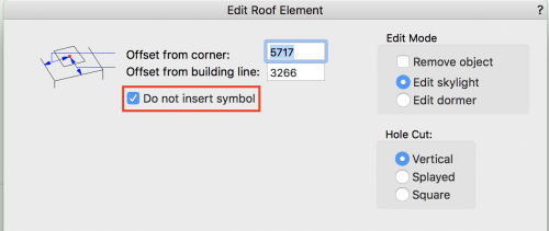
Thought I would test this out and as I thought it does give what you want in the VP. It doesn't really take much time to follow this process. If you want you can still place the symbol but choose to check the box 'do not insert symbol' (another misleading instruction) this will at least create the correct hole size for you. You'll still have to deal with the 'clunky' offset options if you need to move the hole slightly, but you do gain the option to cut the hole with your choice of vert/splayed/square edges which is a nice touch. Still needs fixing though (unless I've missed something). I think you should submit to Bugs.
-
Taproot - Thanks, your file was what it needed. Mind you - Thats a few hours I'll never get back. I tried all sorts components/textures/classes you name it I think Ive got through the lot. Bottom line - I think its a bug. If I create a roof your skylight sits in and displays in the VP. There's certainly nothing wrong with the skylight so its the roof. It seems using a roof face is the issue. To test I also created a 4 part (default) roof and then adjusted the sides to leave it mono pitched as your roof face - and this works fine. I obviously also tried a roof face from scratch and that had the same fault. As an extra - I exported your file as v2017 and opened it with 2017 - No issue so this appears to be something introduced in 2018. Interestingly (possibly for the VW boffins) if you then open the v2017 file in 2018 its happy with 'roofs' coming full circle, but can't resolve your roof face at all and makes a mess of it - resizing and moving. For the moment I think you'll have to stop using roof faces (with bound symbols) and try to get by with roofs or maybe a work around is just to punch the hole first and then place a skylight 'by hand'. I didn't try that, but I would imagine it will work as the skylight won't be a roof face element anymore. Hope this helps. Others might find a different cause.
-
Why is window ID Tag text flipping to inside when removed from wall?
Gadzooks replied to Christiaan's question in Troubleshooting
Thanks Jim. @ChristiaanIf there was some sort of pattern I'd be up for chasing it down, but I think I'm tapped out. Will you submit your OP as a bug. -
Why is window ID Tag text flipping to inside when removed from wall?
Gadzooks replied to Christiaan's question in Troubleshooting
It is though. Granted, Christiaan's OP was that the window retained orientation but the ID tag wouldn't 'play ball', but when you place the window back (as discovered by @Christiaanfrom my example) it flips the opening. This isn't what is expected (?) I think I'd like a response from VW based upon the second of the above if its all the same to you. --------- Edit Sorry - I've made it sound like you are not agreeing. I think you are, but I believe there a little more meat to the query, based upon some time with this particular 'bug'.
-
Why is window ID Tag text flipping to inside when removed from wall?
Gadzooks replied to Christiaan's question in Troubleshooting
Well I did wonder if the 'sloppy' way of inserting the window produced issues - so went to top/plan, but no difference. Haha - Dont think I can use a CAD program where outcomes are confusing and it make a difference the way you hold your face!! (royalty free btw) Lets hope someone's on the case and can provide answers
-
Why is window ID Tag text flipping to inside when removed from wall?
Gadzooks replied to Christiaan's question in Troubleshooting
I see!! Don't know what made you place it back (probably from years of using VW and can't quite believe the outcome doesn't have a spurious side) - but excellent find. Whereas your window doesn't change (except to what you require) if placed back - whats going on? For the license fee, I can do challenging (and am happy to learn more every day), but I'd rather not do confusing - especially when the boffins will have moved away from fixing window creation and be on to some new 'headline' feature (that I possibly didn't even know I wanted). Lol. The window tool is ***********. (don't bother counting the *. It doesn't spell the word I could have used) Something needs to be done with this. @JimW. Even if the answer is "you're not using it correctly" it would be good to find out where we are with this and what the boffins are going to do. -
I thought this might be classes but you say they are turned on (in the VP?) Can you confirm - this is a new 2018 file, or is it something created in 17 and now opened in 18? - Just so we have the complete background to this. I can't replicate this. Can you upload the file? (or a test)
-
@nikihoopsAgree - could be a lot better. But work arounds and your knowledge of VW in that respect will help a lot. Its what the forum is great for. I think if you were drawing this as new build I would use @Christiaan's way as you would end up with more accurate materials shown on plan. HTH
-
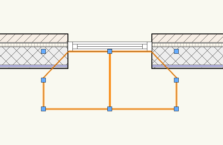
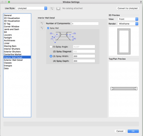
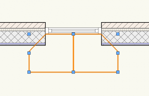
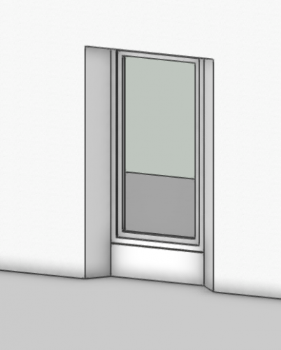
Errr - far right? (no worries - more coffee? lol.) You'd have thought the option to splay was was made for this. Nah - well thought through by the boffins, but flawed by a (lack of) simple addition command set to state where the splays should be. These settings give you this.. Just an extra tick in the box for left and right only would be good. And I can't be bothered to raise the issue of 'finishing' the wall surfaces. - Oh I did (silly me) You could 'fiddle' this (yes VWX needs fiddles/workarounds all the time.) Build an appropriate shape to create a wall recess on the inside of the window. Shape on plan and then extrude - in your case floor level to window head. Highlight wall and 'shape' and Choose AEC > Create Wall Recess.... I've then had to 'dress' the wall finish in. Works, but not as good as VWX boffins could (should) make it. Hope this helps.

-
+1 I agree BG
-
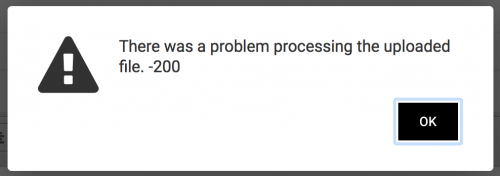
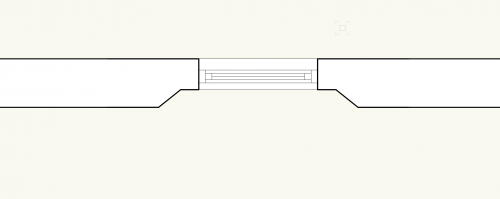
Yes and no - most of this seems to be the complicated way you have constructed the elements. As far as the 'complexity' is concerned, clicking on the 'box' reveals its a solid subtraction (to form the 'letter box') and then clicking on that reveals the 'box' is an extrusion of 4 separate lines. And - I see @Jeremy Bestjust snuck in before me with a better way. I was trying to upload an image built similarly but it seems part of the forum is brocken as far as images are concerned. @BGI tried your file in 2017, but you've posted 2018. Neverless, if it works in 2017, perhaps you should notify a 'bug' ? ---------------- Edit - sorry, missed you out @Benson Shaw- equally reasonable way to fix the prob. I resolved to using 3d polygons. ----------------- Edit again!! - How are you guys uploading images atm? Wont work for me.
-
I think it would help if you posted the file - or a simple file that contains a wall with the sample 'window' elements. It seems from the image posted that the underside of the ptac is lower than the element to the right of it. Is this drawn correctly? Brickwork opening (base) is to remain level? I also note the height of the 'window' is not a brick dim. Does this need to be addressed? I assume the ptac also protrudes forward of the other three 'flat' elements, or is the casing not needed (to be shown accurately) in this exercise? Or the body of the ptac is internal? Would be helpful to have some detail to be borne in mind to develope a solution.
-
Something Brocken??? I dragged and dropped (on another thread) and it worked! - Thanks. But (theres always a but) now it won't allow further screenshots to be placed - even by uploading to the 'container' first. I get.. Which, incidentally, I have dragged into place here as well. (still works - yeh) Now I'll try to add to this .......Nah doesn't like that. For information - the image above is only 36kb and the one I next tried and failed with is 192kb so its not a size issue. @JimWare you still playing with this and you know about the issue?