


Marissa Farrell
-
Posts
1,474 -
Joined
-
Last visited
Content Type
Profiles
Forums
Events
Articles
Marionette
Store
Everything posted by Marissa Farrell
-
@willofmaine I'm going to offer an easier way to solve this without having to mess up your existing network too much - after your "Text" node, use the "Get String" node. I'll also try to explain better what's going on with your current network. Your text node is creating a Vectorworks text object, which is not a String type variable, which is what you really want. The Get String node that I am proposing will take the String variable that exists inside of that text object and pull it out just so you get the characters that make up that Text Object. The text object that you created gives a 'handle' (or a unique identifier for an object in your document) rather than the string because we use that handle to edit that specific object (for example, move, resize, change the text inside, etc.) Hopefully that makes at least a little bit of sense, but if it doesn't I'd be more than happy to get further into it (maybe even with a graphical demonstration )

-

Response time too big for array along path script
Marissa Farrell replied to Alkistis's topic in Marionette
Hi! To start off, you're doing nothing wrong. It looks like the Subtract Solids node is super expensive for this network. That node, by default, will perform a subtraction on each possible combination of the items going into the first port and second port. I attempted to get around this by editing that node to not cross reference the lists, but that ends up removing your trimming on the objects. (it did, however, make the network run faster) I'll keep looking at this, but if you want to try to figure something out, just try to minimize one of your lists going into the Solid Boolean node and that should speed things up. -
Version 1.0.0
266 downloads
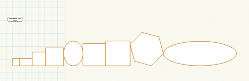
Starting in Vectorworks 2018, users can now create menu commands defined by Marionette networks. To do this, select a wrapper in your file, right click, and choose "Convert to Menu Command..." This will open a dialog window where you can name this command. A background process will save your Menu Command to a file in your User Folder. Once that's complete, you can access the menu command by navigating to Tools > Marionette Commands > [YOUR COMMAND HERE] Try this out with the attached file. After creating your menu command (I named mine 'Arrange By Size' when I created it), select some or all of the objects on the drawing area and run the command! -
I want to chime in and mention that we also added some new stuff to Marionette for those interested, my personal favorite being the ability to create Marionette Menu Commands which now allow you to use your script on selected objects in your document. There is also now a Valve node that will allow you to toggle whether nodes past that point will run or not (great for debugging or conditional network running) And a small set of other nodes that can help enhance your Marionette workflow were added as well. Feel free to reach out to me personally or on the Marionette Forum to get more details and short examples!
-
Vectorworks 2018 System Requirements
Marissa Farrell commented on PVA - Admin's article in Knowledgebase
Not officially at this moment, but it's going through the compatibility testing internally. I would assume there will be an official announcement once that has all been done. -
Currently your network is creating the Rectangles BEFORE your If node, which is why all of the rectangles show up. I think a better approach to this would be to place the If node before your Rectangle node. I've attached a revised network. How is the If node used_MFarrell.vwx
-
Convert a planar NURBS Surface to Polyline
Marissa Farrell replied to Stephan Moenninghoff's topic in Marionette
I don't think there is a function available to us in python to do a surface extraction at this time, so I don't think we can pull this one off until it gets exposed to us. -
Hi! You're going to want to use the "contents" node from the operations category to get the handle to the geometry within the symbol. Place that node after the symbol node and before the get width or get bounding box nodes. I can attach an example when I get into the office, if you need.
-
If you haven't already, I would also suggest running the 'Refresh Libraries' command from the Resource Manager.
-
The installer is the same for the evaluation version and the licensed version.
-
Door Knob Position Unexpectedly Doubled...
Marissa Farrell replied to willofmaine's topic in Marionette
Mine still places the symbol at a 3d position. The other one was just written a bit incorrectly. The end goal was the same for them. -
Door Knob Position Unexpectedly Doubled...
Marissa Farrell replied to willofmaine's topic in Marionette
Absolutely! Please continue to ask for the functionality you need, I'll do my best to get it onto the forums and hopefully into a shipping version at some point. As for VS/Python, we currently just have the Python API call to the existing VectorScript calls, however a lot of the time I'll use generic Python calls to replace anything that isn't Vectorworks specific (such as writing files, manipulating data, unit conversion, etc.) I'm not really in charge of any of it, so I just roll with the punches and do what I can. Either way, there isn't enough exposed to either language to interact with the back end of Vectorworks. -
Door Knob Position Unexpectedly Doubled...
Marissa Farrell replied to willofmaine's topic in Marionette
We're working on adding more nodes, I wouldn't say you're going down the wrong path - there just haven't been many requests for new things. We're also slightly limited in what functions are exposed to Python which is why there are a few things you would *think* we'd have by now missing. That displacement is a bug, we tackled it in 2016 and then 2017, but it keeps cropping up. The workaround is to change your variables and run networks from Top/Plan. Top/Plan will always place things in the correct positions. -
Door Knob Position Unexpectedly Doubled...
Marissa Farrell replied to willofmaine's topic in Marionette
The vectorscript function 'vs.Symbol()' only takes a 2D argument. It's nothing you're doing wrong, whoever wrote that node just didn't realize it at the time. I replaced the node in your file with a node that meets the requirements, so it's not a huge deal, just something to think about. We don't ship that node, so it was created by an outside user. Also, @the frog is using a French version, I believe, which may not be as up-to-date as our version is, which may be why they are seeing more issues than you. Marionette is pretty stable, overall. I almost never have issues with it, and I also don't see what they are seeing. I'll try to find some time to share a simplified network sometime this week -
I'm seeing the same as you, it's probably just some sort of leftover artifact that gets reset when those nodes are moved.
-
If you move the nodes not being included before wrapping, does it wrap OK?
-
Door Knob Position Unexpectedly Doubled...
Marissa Farrell replied to willofmaine's topic in Marionette
So I'm seeing a couple of issues with your networks The Symbol3D node needs to be rewritten. vs.Symbol() takes a 2D point argument, but the whole 3D point is being fed to it - this isn't the issue that's creating the problems in file 15, but it still, nonetheless, can create issues in other circumstances. For some reason, that I still haven't determined, the movement in Z is being applied twice to that symbol instance. I'm attaching a network that will prevent that, and though it's not the BEST solution, it will absolutely handle that case. Another note, Marionette doesn't like when nodes are named beginning with a number, or when they include non alphanumeric characters (In this case, your '2 Knobs Option' node) So I've renamed it to 'Two Knobs Option' This network can probably be written more efficiently. If you'd like, I can try to help you out with that when I have some free time 15-Cabinet_Door-2nd_Knob_Optional-14_MFarrell_v2017.vwx -
Yep, @Pat Stanford is correct, though this was also true in 2016. Marionette can be adapted to most cases, so it's just a matter of figuring out exactly what you want to do before tackling the logic behind it.
-
I'll try to answer these as clearly as I can, but if I fail to make sense, let me know and I will try to clarify further. In the network I shared, I already had a symbol on the drawing area, so I used the Name node to reference that specific instance. The Name node will search for an item in your document that matches that name (this can be an object, a layer, and some other types of objects in Vectorworks that have what is called a 'handle', which basically is a unique identifier) When you made your network using the Symbol node, the Symbol node actually returns the 'handle' to the newly placed Symbol instance in your document, and since the ScaleSymbol3D node wants a 'handle' as an input, the network ran correctly. The Symbol node takes a String input (the name of your Symbol in the RM) because it looks specifically at symbols and not all types of Vectorworks objects. As for the difference between the Name node and the String node, the Name node has a very specific use (returning the handle to an item, as stated above), whereas you can use a String for multiple uses (i.e. defining what a Text node will put on your drawing area, naming an object, or pretty much any other thing you would type a word into) There currently isn't an official (or even unofficial, to my knowledge) document/database that gives more specific uses for nodes, HOWEVER we are in the process of adding prefixes to all of the ports on nodes to help users easily identify what type of data is flowing out of a node's port, as well as what type of data a node's port is expecting. (Which is why you saw my new Name node has 'h' as the output port, which refers to a type of 'handle') There's a plan in the pipelines later to expand upon use cases for nodes on a more descriptive level, but that will likely take a lot longer than defining what type of data is flowing through wires, so we tackled that goal first. I hope this helps clear some things up, but if you need a little more description on anything, let me know and I'll happily keep going
-
The problem you're encountering is that you're trying to match the string in the Name node to the name of your symbol in the Resource Manager. Name has to match the name of your symbol on the document in the Object Info Palette. So in my original file, I named the symbol instance "s" in the OIP and the Name node references "s" in the OIP. Let me know if you still need help! (Also, obj and h are irrelevant. We're internally changing the prefixes of ports on nodes to be more helpful for the user. This will make more sense later )
-
convert to polygon doesn't work in marionette object
Marissa Farrell replied to Benny Keyaerts's topic in Marionette
I found the problem, and it is within the Convert to Polygon node. For some reason, we're setting the planar reference again and then trying to move it, which I believe in most cases is unnecessary, though I'm sure it was included for a reason, it just seems to not work when in a Marionette Object's coordinate space. (Likely because in a Marionette Object, planar objects default to screen plane, and we try to move it's location in the Z direction which does not exist in screen plane, whereas when you run a Marionette Network on your drawing area, all objects are drawn to the layer plane.) I'll see if I can insert some logic in there to remedy this. Thanks for pointing it out! -
Anytime
-
convert to polygon doesn't work in marionette object
Marissa Farrell replied to Benny Keyaerts's topic in Marionette
Hi @Benny Keyaerts Try throwing in a 'delete' node after the rectangle. It looks like both the rectangle and polygon are being kept instead of just the polygon. I'm not quite sure why this is, but it's a start! convert to polygon_MFarrell.vwx -
Here's the ScaleSymbol3D node. Right now you just have to make sure that you have your symbol set to Scaling: Asymmetric in the Object Info Palette, but I'll see if I can find something that will automatically set that for you. EDIT: Got it. File updated. ScaleSymbol3D_v2017.vwx
-
What would you suggest I name this node?
