
zoomer
-
Posts
8,903 -
Joined
-
Last visited
Content Type
Profiles
Forums
Events
Articles
Marionette
Store
Everything posted by zoomer
-
VW2024 Doors - how to change hinge side on a swing bi-part configuration?
zoomer replied to StefanoT's question in Troubleshooting
Thanks for all answers and bug reporting ! -
Really !? Why not just assigning a XY, XZ or YZ Plane by keeping the 3rd Axis zero ?
-
I didn't really use VW (2024 SP2 on Sonoma) so far .... But I also notice some lags when opening, beside my current file, just another empty new file from a template. (No matter if my own migrated or a VW blank template) And playing with a bit between medium/max GUI option finally needed a VW restart as I got 3 non functioning ghost palettes of my (auto)collapsed Resource Manager and all palettes looked undocked and overlapping each other .... Just going to Home Screen or closing and restarting the File did not help.
-
Rhino.Inside for Vectorworks
zoomer replied to elepp's question in Wishlist - Feature and Content Requests
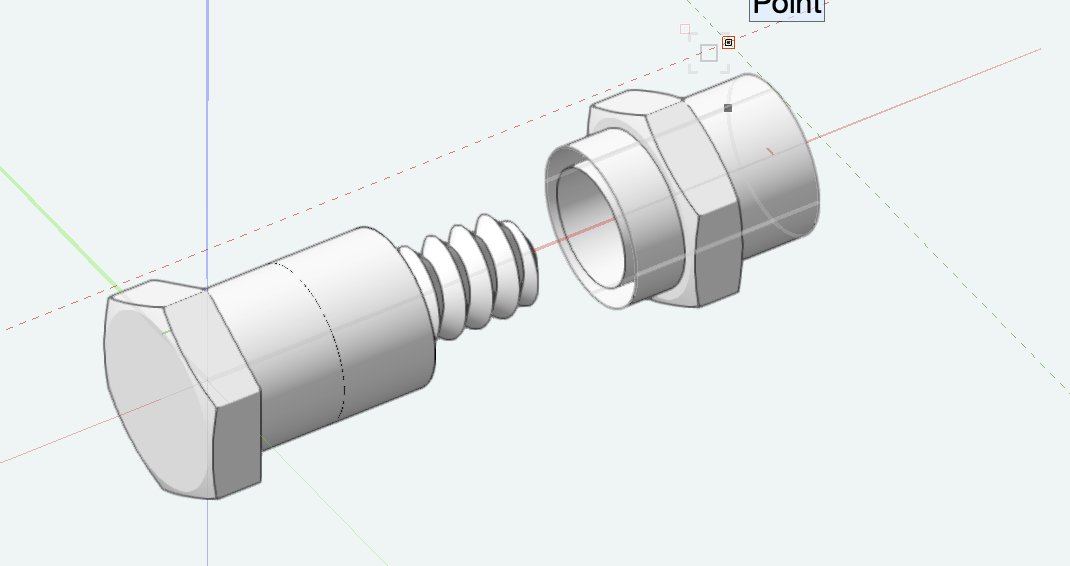
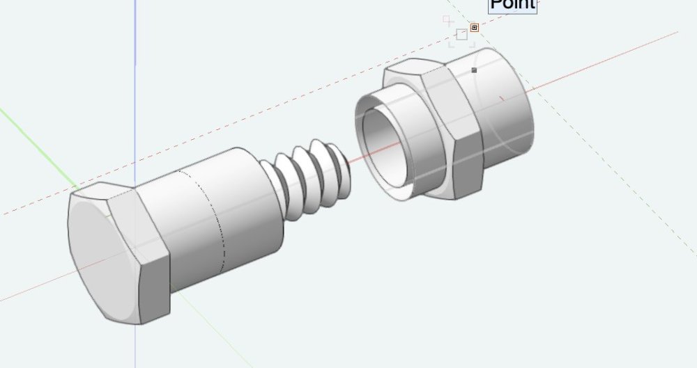
OK I took the Bolt demo file from here : https://www.rhino3d.com/plugins/bongo/docs/sample-models/ Arrgghh, Bricscad Rhino Import is Windows only .... But I went through all PC hazzles. Bricscad imports (the screw part only !? ****) but it is a true ACIS Solid : So I think, if VW would it could also import Generic Solids. I just assume, as VW also has NURBS functionality, they wanted to keep the NURBS control (?) (***) Probably because the Washers seem to be hollow, as it looks for the VW NURBS Faces import ....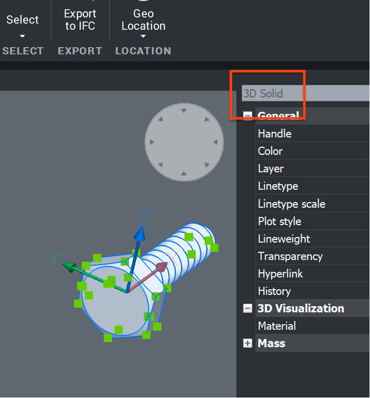
-
VW2024 Doors - how to change hinge side on a swing bi-part configuration?
zoomer replied to StefanoT's question in Troubleshooting
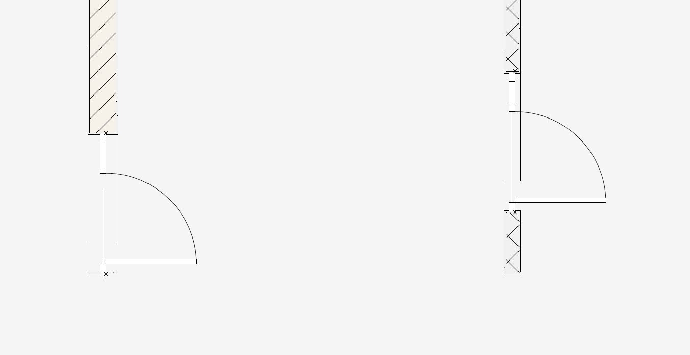
@Matt Panzer Oh, I got it now .... I do not need to "mirror" my Doors (with a side light). I searched for and expected, a left+right sidelight checkbox/setting option but it was just hidden in numeric inputs .... Nevertheless, this way I was now able to re-orient my Doors with a side light correctly ! (BTW 1 Why did 23 to 24 migration "mirrored" my Doors in the first place !?) (BWT2 is there an option to find which Objects you mirrored - later - which you shall not had mirrored) However, geometry of the Doors (using Jamb Extension + top + side lights ...) looked much better at first glance in VW 2024. 👍 But I still see some strange overall Door appearance in Top Plan View (strange interrupted Lines at Wall thickness level) and I am not able to control my "Thresholds" ("Under Leave only" !?) Of course that happens in 3D also, not only top plan view .... So in case anyone interested in, I will add a Screenshot and Test File. What I want is a "Threshold" that mimics a 5 mm iron L-Profile, used to stop/seal the Door Leaf bottom side (Usually there is a 2 cm height level difference between both Floors) and to separate the Floor Materials between Rooms of a 1960ies residential house. Untitled 3.vwx
-
Rhino.Inside for Vectorworks
zoomer replied to elepp's question in Wishlist - Feature and Content Requests
I did not really speak for VW imports 🙂 I just meant that AFAIR I have seen that already or think it would be possible that importing Rhino could bring in Solids .... Was there a link to any suitable Rhino File that I could test ..... -
Rhino.Inside for Vectorworks
zoomer replied to elepp's question in Wishlist - Feature and Content Requests
I think Rhino is not Mesh based. It is mostly NURBS based. So like a Mesh it feels like non-Solid but (NURBS)Faces only. But Rhino can make feel its volumetric NURBS Faces like Solids or NURBS Faces like simple planar Faces. (BTW, I hate that 2nd order NURBS cross in each Face ... AFAIK if you do not actively suppress this, it will also export Faces that way) Just if you are an unexperienced user and use the wrong Tool, you likely will accidentally pull out a Solid's Face or distort one of your planar Faces with ease. So I think between most clear (ACIS, Parasolid, ...) CAD Volume Modelers and typical Mesh Modelers (Blender, 3DSMax, C4D, Modo, Maya, ..........) or some do it all combos like FormZ, Rhino is its own phenomena with NURBS first approach. But I would bet that Rhino "Volumes" can come into other Apps (Bricscad (?)) as Solids if needed. As it also seems towork by IFC imports, but I would need to test that if that also works with IFC exported from true Mesh Apps, like via BlenderBIM ..... -
Rhino.Inside for Vectorworks
zoomer replied to elepp's question in Wishlist - Feature and Content Requests
I think this is Modo's Modifier Stack or Blender's Geometry Nodes or even iterative things like Grasshopper. Or something like Mechanical CAD (?) But where can you do that in VW ? Edit Path or Profile in EAP, change the Profiles of an Extrude ... just 2 steps. With Solid Add/Subtraction/... and Fillets, you will get a few more steps. But AFAIR editing components of multi step Solid Subtractions wasn't very reliably for me in the past (?) Or with Marionette ... as long as you stay inside your Marionette envelope ? -
Rhino.Inside for Vectorworks
zoomer replied to elepp's question in Wishlist - Feature and Content Requests
I like destructive modeling. Starting with Microstation I was used to make copies/backups of important model steps, if needed. 3DSMax like C4D worked primarily with modifiers, so non destructive. But I soon realized that I can convert everything to a Mesh and edit all parts at a time, without losing any control. Modo at the beginning was absolutely destructive modeling only and I did not miss anything. When in a destructive modeler, you just need to have the proper editing tools which Modo had. And as far as Selections, Item Tree/manager, Object Info, Modeling and Editing Tools, Preview, Render Settings, Material control, .... I still miss that standards in any other 3D or CAD Apps so much. On the other hand I like parametric Objects in CAD/BIM. I even prefer it for architectural modeling. Like VW's PIOs and Styles. I could not live with my basically totally destructive Bricscad's Solids modeling approach though. And for Solids I do not want any history I want them to be cleaned up, optimized and simplified for absolute reliability after each operation. -
Relinking Reference files with version upgrade - any hacks?!
zoomer replied to Sarah Harrison's question in Troubleshooting
I usually copy the Reference files as they are into a "VW Version before" Subfolder. Batch Convert the original References in place to VW Version current files. So I can open the migrated master file in VW Version current and the References are still working. Of course, if you want to open the previous master file version, you need to relocate your References again though. But usually I did not have so much problems with the newer VW version that I would need to go back. An alternative is to rename References according to VW Versions. Needs a single reloading References for each VW upgrade. But you can still open your previous VW file version's References without issues. Or you could copy the whole file related parts of your project folder with each VW upgrade and run batch convert for all VW files including all subfolders. So likely not the answer you hoped for and not very comfortable. But I think I would not have a better idea how to organize these upgrades or what VW should make better (?) -
I think Mograph is ok. But that was reserved for decades for a C4D Studio or that other Version. It was not available for base C4D or Architecture. Therefore there happened some alternatives like surface spread. Maybe even easier to use in our non motion graphic usage. But since there C4D is only available as the full package, it may not always be worth to use one of the alternative replicators.
-
BTW, I would prohibit that. I am an idealist, not pragmatic or result orientated. I am not interested to see the mediocre reality but the initial idea. When I would get a such point cloud or site measurement, in my other CAD, I would use Face Detection and let it create Walls and Slabs from it .... but immediately after I would start Optimize Command Suite - with a 15° and 2 cm Tolerance and let flatten it to the way it was meant to be build. I mean, even Egyptians were able to level their pyramid sites exactly and for their Obelisks, even those made of rough stones, you can feel that they used a lead line and the overall appearance is absolutely straight. So if that idealism does not fit the build reality and ideal planning results in problems fitting things in I would advice the customer to use a Milling Machine to bring that back to order. 😅
-
I would not argue that your Section Line has not the exact same angle. But could imagine that the Section Engine, when estimating the parallel-ness of the Symbol for sharp angles, may potentially find a little difference in 12th+ digit that it assume it is not square to Section and decides to reject the 2D addon and start the Symbol appearance calculation from the Symbols 3D part instead (?) So like the Photomatch Tool that gets crazy when your photo is nearly from a 1 point perspective (?)
-
When I read this my first thought was ..... ohohoh, will this work ... I would think it is a general computer accuracy problem. The more "only slightly off" the angle the worse ? I would assume 30° or 45° would be much less error prone.
-
I think click to select and DEL or BACKSPACE. But maybe you do not need delete it. When Selected you can set it temporarily to invisible in object browser or just move it downwards. But if you check object browser, you should already if your VW data came in or not. EDIT : I read you already see the data in manager, but not on screen. And if I got that right your DTM should be at a positive Z height .... Then it might be a different problem. Not sure if I ever exported a VW DTM to TM so far.
-
Usually when nothing is there it is geometry sub Z 0,00, which will just be occluded by TM's default ground plane at Z 0,00. You can delete that default ground plane and check if your geometry was below or is really not there.
-
I also think it should be that way. I just have seen it also different.
-
I did that all the time with VW to C4D Exchange. I pulled out all versions related objects on extra temporary Version Layers in VW. What you do with SLVPs and Publish, you can do very comfortable in C4D and "Render Takes" system. Exchange was usually a sub 10 second "send to C4D" and sub 5 second load in C4D and pretty reliable. And you have the comfort of automatic custom output naming à la Prefix ProjectName $CameraName $YYYYMMDD $hhmmss Suffix ... to your liking (Usually most done via RenderTakeName ...) You can start such batch rendering process when you leave the office and could be sure it's there next morning.
-
Opposed to Walls, for Slabs it is pretty easy. Myself and many others use Slab sandwiches .... The Structural Slab and a separate Floor Packe Slab on top. If needed also an Insulation package (or Ceiling stuff) below. Does currently not work for Walls because of the inserted PIOs. Does work for Slabs mainly because Slab openings usually do not change that often. But a change in thickness would be no fun for Slab packages either.
-
A "Component Container" ?
-
Just that Revit App and Revit users aren't always very ambitious in producing proper IFC exports. My experience is that IFC is only a giva-away for the few non Revit participants and BIM master model coordination isn't done in an IFC App but in Navisworks. Closed BIM.
-
😃 I think we agree. (But you were faster)
-
I ran into this too. Meanwhile we have building materials which helps to creates new Styles from scratch. But changes in thickness can get very tedious. So we also need "Component Styles" E.g. Concrete-Style A : concrete X, 20 cm, structural, .... And when you have to change thickness to 25 cm in Style, all Wall Styles will follow (?)
-
First, I always postulate that BIM CADs need to separate Structure from Finish. You may likely have 10-20 Finishes and 10-15 Structure Styles. But in all needed combinations that does no more make sense. OK that needs also intelligent PIO Insertions like Windows and Doors that are able to cut into more than a single Wall. If the Finishes are defined by Space settings and or outer/inner building element state - don't know. My other CAD at least allows to manually assign cutting elements to also cut other objects. And for Styles, it has an option for a variable thickness for one of the components. (Like the same concrete Slab package that uses multiple thicknesses for the structural Slab, according to bearing needs) This saves a lot of Styles or their similar duplicates. As we are in VW .... As long as it makes sense I do have Style Duplicates. Exceeding that, I may start searching for some workarounds.
-
Navigation palette fails to refresh when switching between files
zoomer replied to StefanoT's question in Troubleshooting
So a similar issue like with Visualization Palette (?)